1
SMALL-SIZE EXPLOSIVE GAS
MEASURING SENSOR
MIPEX-03-Х-XX-X.X
USER MANUAL
ESAT.413347.006 UM
REV 0.7 Dated 14 April 2015
ESAT.413347.006 UM MIPEX-03-Х-XX-X.X USER MANUAL
Table of Contents
INTRODUCTION ................................................................................................................. 3
1.
DESCRIPTION ............................................................................................................ 4
2.
TECHNICAL SPECIFICATIONS................................................................................. 5
3.
INTRINSICALLY SAFETY .......................................................................................... 6
4.
PRECAUTIONS .......................................................................................................... 7
5.
INSTALLATION AND SERVICES .............................................................................. 8
6.
DESCRIPTION OF ANALOG OUTPUT .................................................................... 11
7.
STORAGE AND TRANSPORTATION ..................................................................... 14
8.
WARRANTY ............................................................................................................. 15
9.
CONTACTS .............................................................................................................. 16
Appendix А. Sensor types and characteristics. ............................................................ 17
Appendix B. Connection diagram. ................................................................................. 22
Appendix C. UART communication protocol. ............................................................... 24
Appendix D. Sensor zeroing and calibration. ............................................................... 29
Appendix E. Attaching the dust filter. ............................................................................ 32
List of abbreviations:
CGM – Control Gas Mixture;
EMI - Electromagnetic Interference;
LEL – Lower Explosive Limit;
MCU – Microcontroller Unit;
NDIR - Non-Dispersive Infra-Red;
UART - Universal Asynchronous Receiver/Transmitter.
REV 0.7 Dated 14 April 2015
2
ESAT.413347.006 UM MIPEX-03-Х-XX-X.X USER MANUAL
INTRODUCTION
MIPEX-03-Х-XХ-X.X (hereinafter, sensor or MIPEX-03) is the gas sensor, which is
intended for automatic continuous measurement of concentration of hydrocarbons in
explosive areas and carbon dioxide.
Sensor can be used as part of gas-analyzing equipment of groups I and II according to
IEC 60079-0 in the explosion-hazardous zones of classes 0, 1, 2 according to IEC 6007910-1, and Class I, Division 1 according to UL913, CAN/CSA-C22.2 No. 157-92.
Optosense LLC reserves the right to update and change current UM in parts
exclude intrinsic safety parameters and accompanied information specified below.
REV 0.7 Dated 14 April 2015
3
ESAT.413347.006 UM MIPEX-03-Х-XX-X.X USER MANUAL
1. DESCRIPTION
The principle of sensor operation is based on NDIR technology.
The infrared radiation of a light-emitting diode permeates a measuring diffusion-type
gas cell and gets at 2 light-sensitive cells; one of them is responsive to radiation in the
range of wavelength of 3.25 to 3.45 m only, while the other one registers radiation in the
range of wavelength of 3.1 to 3.25 and 3.45 to 3.7 m. The investigated gas present in the
cell absorbs radiation of the operating wavelength (o) and does not affect radiation of the
reference operating wavelength (r). The amplitude Io of the light-sensitive cell operating
signal changes upon changing concentration in accordance with equation:
Io/Ir = ехр {-[К(o) – К (r)]СL};
(1)
where:
К () – coefficient of absorption at a given wavelength;
L
– optical length of cell;
С
– measured concentration of gas;
Io, Ir – amplitude of signals at light-sensitive cell.
The concentration of gas is:
С = -Ln (Io/Ir)/(L [K (o) – К (r)]);
(2)
Using differential dual wavelength method of registration allows eliminating influence
of water vapor, contamination of optical elements and other non-selective hindrances
affecting both channels similarly.
The sensor structure contains an optical cell with a mirror system, infrared lightemitting diode (LED), LED driver, receivers of Signal and Reference channels, analog
amplifiers, microcontroller and supply voltages unit.
The microcontroller of the sensor performs:
- storage of unique calibration constants;
- calculation of gas concentration based on measured results;
- communication though UART and analog output interface.
The sensor is enabled on power is up and disabled on power is down.
REV 0.7 Dated 14 April 2015
4
ESAT.413347.006 UM MIPEX-03-Х-XX-X.X USER MANUAL
2. TECHNICAL SPECIFICATIONS
Table 1. Technical specification.
Gas sampling method:
Operating principle:
General
Target gas *
Operating,
storage and
transportation
conditions:
Relative humidity
Atmospheric
pressure
Temperature range
Overall dimensions *
Pins length
Weight *
Enclosure *
Electrical
Measurement
MTBF
Measurement range *
Accuracy *
Response time, T90 *
Temperature, pressure and humidity
performance
Supply Voltage Range:
Output signal *:
Power consumption:
Warm-up time:
Degree of personal protection against
electrical shock caused by the sensor
Marking and standards
compliance
Diffusion
Non-Dispersive Infra-Red (NDIR)
CH4
CH4 /CH4 +С2Н6
C3H8
C02
up to 98%
80-120 kPa
-40... +60 °C
ø20х16.5 mm without pins
ø22х16.5 mm without pins
4,6
16,6 g
15,5 g
5,5 g
Stainless steel (standard and fast response versions)
Plastic
10 years
100% Vol
5% Vol
2.5% Vol
100% LEL
1.5% Vol
ALARM SENSOR
50% LEL
±0.1 % Vol or ±5 % of indication
±3 % LEL or ±5% of indication
10s
20s
30s
60s
According to Appendix А.
3.0 – 5.0 VDC
digital UART, analog output
<5mW
not more than 1 min
meet the requirement of class III GOST 12.2.007.0
Ex ia I Ma/Ex ia IIC Ga. acc. to IEC60079-0, IEC6007911, IEC60079-26. -40⁰ ≤ Ta ≤ +60 ⁰C
IM1/II1G Ex ia I Ma / Ex ia IIC Ga. acc. to EN60079-0,
EN60079-11, EN60079-26. -40⁰ ≤ Ta ≤ +60 ⁰C
* Available options. See Appendix А for details.
REV 0.7 Dated 14 April 2015
5
ESAT.413347.006 UM MIPEX-03-Х-XX-X.X USER MANUAL
3. INTRINSICALLY SAFETY
Combined intrinsically safe parameters of sensors circuits are as follows:
IECEx/ATEX: Ui = 5.0V, Ii = 200mA, Pi = 0.13W, Ci = 5.95µF, Li = 0.
CAN/CSA: Vmax = 5.0V, Imax = 200mA, Pmax = 0.13W, Ci = 5.95µF, Li = 0.
It is allowed to connect the sensor only to intrinsically safe circuits with the rated direct
current output voltage (U0) within the range of not less than 3 V and not more than 5 V, with
the output power (P0) - not less than 0.02 W and not more than 0.25 W.
The gas-analyzing equipment, which is used with MIPEX-03, must meet the
requirements of IEC60079–0, IEC60079–11, IEC 60079-14 and have parameters
conforming the MIPEX-03 intrinsically safe pointed above.
REV 0.7 Dated 14 April 2015
6
ESAT.413347.006 UM MIPEX-03-Х-XX-X.X USER MANUAL
4. PRECAUTIONS
Inspection and maintenance of the sensor shall be carried out by suitably trained
personnel in accordance with the applicable code of practice (e.g. EN 60079-17).
The persons who have studied this UM, have been briefed on safety precautions when
operating electrical equipment intended for operation in the explosion-hazardous
zones in the established order, are admitted to operate the sensor.
Repair of the sensor shall be carried out only by personal of manufacturer or
authorized by manufacturer.
It is interdict to discharge the control gas mixture (CGM) to the atmosphere during
sensor calibration.
Do not allow the contact of sensor with aggressive substances e.g. acidic liquids or
gases that may attack metals, or solvents that may affect polymeric materials.
REV 0.7 Dated 14 April 2015
7
ESAT.413347.006 UM MIPEX-03-Х-XX-X.X USER MANUAL
5. INSTALLATION AND SERVICES
MIPEX-03-X-XX-3.X POTENTIAL ELECTROSTATIC CHARGING
HAZARD – CLEAN ONLY WITH A DAMP CLOTH. The external part of
the sensor can be sourced of risk of electrostatic discharge. Take it into
account during installation and operation of the sensor in end-user
equipment.
The MIPEX-03-X-XX-1.X and MIPEX-03-X-XX-2.X models of the
equipment were tested and found to hold 18.3pF maximum capacitance.
Connection should be made via PCB sockets. Soldering to the pins will
seriously damage the sensor.
Excessive force on sensor housing is not allowed: no more than 2 MPa
applied to reflecting cover center or on at any point of middle part side
surface and no more 200 MPa applied to boundary of reflecting cover.
Metrological properties are not supported in ambient temperature
gradient faster than 0.6 ⁰ C/min.
5.1 Preparation
5.1.1 If the sensor has been kept in the transportation package at temperature
lower than 00C, hold it at temperature of 10–35 0C for at least one hour.
5.1.2 Remove the packing. Check presence of the certification marking, ensure
absence of mechanical injuries.
5.2 Installation
Use intrinsic safety connection given in Appendix B.
5.2.1 Use recommended sockets Cambion 450-3326-01-06-00 for the sensor
connection or similar. Sensor pinout is shown in Appendix А.
5.2.2 Provide power supply of the sensor from power sources featuring nominal
range of output DC voltage of not less than 3 V and not more than 5 V, output
power (P0) – not less than 0.02 W and not more than 0.25 W in accordance
with requirements of standards IEC 60079–0:2004, IEC 60079–11:2006. For
all MIPEX-03 modification polarity of power supply does not matter.
5.2.3 The transceiver of serial interface UART for MIPEX-03-X-XX-X.2 and MIPEX03-X-XX-X.3 should meet the requirements of standards IEC 60079–0,
IEC 60079–11.
Communication parameters of UART-transceiver are following:
- HIGH logic level for TxD line of sensor is 2.8V;
- HIGH logic level for RxD should be at range of 2.8V…3,3 V;
- LOW logic level 0 V;
- Maximum output current of UART not more than 25 mA.
REV 0.7 Dated 14 April 2015
8
ESAT.413347.006 UM MIPEX-03-Х-XX-X.X USER MANUAL
5.2.4 Analog output (AnOut) for MIPEX-03-X-XX-X.1 and MIPEX-03-X-XX-X.2
should be connected to R load. Recommended R load is 10kOhm. Maximum
output current of AnOut is 10 mA.
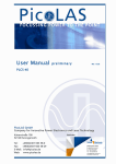
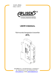
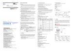
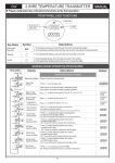
MIPEX-03 has pulsed power consumption. Maximum current may
shortly rise up to 10 mA during 10ms pulse length. Average
consumption is less than 1 mA (see Fig. 1 and Fig. 2).
In case of the sensor sends the commands via UART maximum
current consumption may rise up to 10 mA during 60 ms.
After power up, during 60s warm-up time, the sensor does not
return the concentration value (the value displays as “-1”). After
that sensor starts to transfer measured values.
After warm-up (1 minute after power-up) the sensor makes selfdiagnostic test during 2 minutes.
Please note, if the dust filter from sensor’s kit was attached, then
ZERO2 command must be send after Warm-up time.
Sensor updates information about concentration every approx. 1.3
sec. Sending command more often than 1 time per sec (1 Hz
sampling rate) is not recommended, otherwise the temperature
sensor accuracy comes down.
5.3 Proper use
The sensor outputs information about measured concentration value though the digital
serial interface UART or analog output (see chapter 6 for details). Data communication
protocol is given in Appendix C. Methods of setting zero of the sensor and re-calibration are
given in Appendix D.
The sensor is designed for continuous operation.
There is self-testing algorithm inside the firmware code.
REV 0.7 Dated 14 April 2015
9
ESAT.413347.006 UM MIPEX-03-Х-XX-X.X USER MANUAL
Fig. 1. Typical current consumption waveform vs. time (R=30 Ohm, C=20 uF)
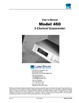
Fig. 2. Typical barrier voltage output vs. time (3.3V input)
REV 0.7 Dated 14 April 2015
10
ESAT.413347.006 UM MIPEX-03-Х-XX-X.X USER MANUAL
6. DESCRIPTION OF ANALOG OUTPUT
Preset of analog output (AnOut) must be additionally noted within purchase order. For
MIPEX-03-X-XX-X.1 and MIPEX-03-X-XX-X.2 models the range of output voltage can be
configured through UART. Henceforth, the range of output voltage might be reconfigured by
user. For MIPEX-03-X-XX-X.1 (3 pin model) this operation will require MIPEX-03 special
contacting device and configuration unit (acquire separately).
AnOut UART configuration procedure:
6.1 Setting up the output mode
The command DACMODE is used to set analog output mode. There are four possible
modes of analog output:
DACMODE0 - switch off analog output. Digital interface is used if available;
DACMODE1 – initiate the mode, where 0.4V output is relative to zero gas
concentration and 2.0V is a maximum;
DACMODE2 - initiate the mode, where half of input voltage is relative to zero gas
concentration and maximum concentration relative to maximum output voltage
(pellistor replacement POSITIVE adaptation).
DACMODE3 - initiate the mode, where half of input voltage is relative to zero gas
concentration and maximum concentration relative to minimum output voltage
(pellistor replacement NEGATIVE adaptation).
Depends on sensor polarity in user device the commands DACMODE2 / DACMODE3
could work in converse modes.
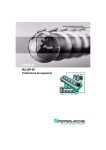
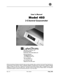
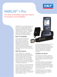
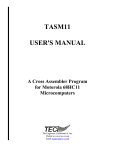
Default setting of a Digital-Analog Converter (DAC) is 0.4…2.0V. Using analog output
in DACMODE1 mode is possible to adjust DAC range using command SETDAC1 XXXXX
(to set MIN output) and SETDAC2 XXXXX (to set for MAX output) where XXXXX is DAC
readings in range 0… 04095. To request current DAC settings send SETDAC?. The
response is relative to MIN and MAX output.
Fig. 3. UAnOut(C) for DACMODE1.
REV 0.7 Dated 14 April 2015
11
ESAT.413347.006 UM MIPEX-03-Х-XX-X.X USER MANUAL
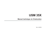
Fig. 4. UAnOut(C) for DACMODE2.
Fig. 5. UAnOut(C) for DACMODE3.
6.2 Setting up the output range.
ALMH XXXX is ASCII command to setting up the concentration value XXXX (in
%Vol*100) for upper voltage output level for any DACMODE.
For example, to set up measuring range 0-5%Vol of CH4 for full scale voltage output,
send in ALMH 0500 command. To set up 100%Vol, send in ALMH 9999.
6.3 C (UAnOut) and UAnOut(C) conversion.
MODE
C (UAnOut)
DACMODE1:
C
DACMODE2:
C
DACMODE3:
ALMH * (U AnOut 0,4)
160
ALMH U AnOut
0.5
50
U sup
ALMH
U
C
0.5 AnOut
50
U sup
UAnOut(C)
U AnOut 0,4 160 *
C
ALMH
U AnOut U sup * (50 *
C
0,5)
ALMH
U AnOut U sup * (0,5 50 *
C
)
ALMH
REV 0.7 Dated 14 April 2015
12
ESAT.413347.006 UM MIPEX-03-Х-XX-X.X USER MANUAL
Where:
C is gas concentration, in %Vol,
UAnOut is output voltage in V,
Usup is sensor power supply voltage in V.
ALMH – concentration for upper voltage level, in %Vol*100.
See illustrations on Fig. 3, Fig. 4 and Fig. 5.
EXAMPLE:
Aim: Need to have AnOut with range 1.5-2.0 V for 0-5%Vol CH4 , Usup= 3.0V.
Solution:
1. Send DACMODE2 and check that response is “Ok”.
2. Calculate ALMH coefficient:
ALMH
50 * C MAХ
U CMAХ
ALMH
U sup
0,5
50 * 5%Vol
250
1500
2.0V
0.5 0.16667
3.0V
3. Send ALMH 1500 and check that response is “Ok”.
4. UAnOut to C conversion is:
C
1500 U AnOut
0.5 10 * (U AnOut 1.5)
50 3.0
REV 0.7 Dated 14 April 2015
13
ESAT.413347.006 UM MIPEX-03-Х-XX-X.X USER MANUAL
7. STORAGE AND TRANSPORTATION
The transportation of the sensors should be performed by all means of transportation
in covered transportation vehicles as well as in the heated pressurized plane compartments
in accordance with the rules of cargoes transportation effective for the respective type of
transportation.
The sensors in the Manufacturer’s package should be kept in the Supplier’s and
Customer’s storages under storage conditions pointed in Table 1. The atmosphere of
storage premises should be free from harmful admixtures provoking corrosion.
REV 0.7 Dated 14 April 2015
14
ESAT.413347.006 UM MIPEX-03-Х-XX-X.X USER MANUAL
8. WARRANTY
The Manufacturer guarantees compliance of the sensors with specifications and
requirements stated in this UM if Customer meets conditions of operation, transportation
and storage.
During the warranty period, Manufacturer has the right to replace or repair all the
products that, according to his unquestionable judgement, are found to be defective, if
defect is due to a fault of Manufacturer.
The warranty period is 24 months since the date of sensor shipment to a Customer.
The date of shipment is registered in the ESAT.413347.006 PS datasheet.
Manufacturer is not responsible for the sensors failure and discontinue in case of:
violations of conditions of operation, transportation and storage stated in UM;
sensor has marks of unauthorized repair;
mechanical damages, appeared after handover the sensors to Customer, effect
of temperature and pressure beyond conditions, chemical erosion, ingress of
foreign substances inside the body of the sensor;
defects due to electrical interface unspecified by UM and other documentation
conveyed to the Customer;
defects due to force majeure circumstances, disastrous occurrences, intended
or reckless act of Customer or third party;
defect or failure due to installing, damaging, changing or erasing of sensors
firmware or changing sensors settings because of misuse of service codes via
UART.
defect or failure due to using power or signal cables unspecified by technical
regulations and standards or operating the sensor with EMC influences
exceeds maximums specified in IEC 61000-4-3.
Replacement or repair of defective sensor does not lead to setting a new warranty
period.
The Manufacturer is not responsible for possible damages, direct or indirect inflicted to
people or properties if this is happened in case of repair, storage and transportation rules
violation or due to purport or reckless act of Customer or third party. The Manufacturer does
not respond as well for possible damages, direct or indirect inflict to appropriate equipment
as the result of change, damage or data loss.
The warranty repair or replacement is effecting in site of Manufacturer or designated
representative.
Shipping and packaging charges and any other incidental expenses for the products
returned to Manufacturer will be at the Customer’s own risk and charged to him.
REV 0.7 Dated 14 April 2015
15
ESAT.413347.006 UM MIPEX-03-Х-XX-X.X USER MANUAL
9. CONTACTS
MIPEX Technology /Оptosense LLC
27, AD, Engelsa prospect, St. Petersburg, 194156, Russia,
Tel./fax: +7 (812) 633-0594, 633-0595
web: http://www.mipex-tech.com
e-mail: [email protected]
support: [email protected]
REV 0.7 Dated 14 April 2015
16
ESAT.413347.006 UM MIPEX-03-Х-XX-X.X USER MANUAL
Appendix А. Sensor types and characteristics.
MIPEX-03-B-RX-C.D
Output format:
1. - analog, 3 pins, pellistors replacement
2. - digital and analog, 5 pins;
3. - digital, 4 pins.
Construction:
1. - stainless steel, “Standard”;
2. - stainless steel, with side holes, “Fast
response”;
3. – plastic.
Application:
R – calibration gas and range
X - temperature class and accuracy
(see Table 5 for details).
Target gas:
1.
2.
3.
4.
- CH4, methane;
- C3H8, (CnHm, hydrocarbons);
- CO2, carbon dioxide;
- CH4/CH4 +С2Н6 acc. to IEC 60079-29-1
MIPEX model number
REV 0.7 Dated 14 April 2015
17
Table 2. MIPEX-03-X-XX-1.X types, interfaces and overall dimensions (stainless steel).
REV 0.7 Dated 14 April 2015
ESAT.413347.006 UM MIPEX-03-Х-XX-X.X USER MANUAL
Table 3. MIPEX-03-X-XX-2.X types, interfaces and overall dimensions (stainless steel with side holes).
REV 0.7 Dated 14 April 2015
19
ESAT.413347.006 UM MIPEX-03-Х-XX-X.X USER MANUAL
Table 4. MIPEX-03-X-XX-3.X types, interfaces and overall dimensions (plastic).
REV 0.7 Dated 14 April 2015
20
Table 5. Individual specifications by type of MIPEX-03.
Calibration
gas
CH4
CO2
CH4
Measurement
range **
50LEL (0-2.5% Vol
- alarm sensor)
5% (0-5 Vol.% –
measure, 5-100%
Vol – indication;)
100% (0-100 % Vol
– measure;)
1,5% (0-1.5 % Vol
– measure, 1.52.5% Vol –
indication)
50LEL (0-2.5% Vol
- alarm sensor)
5% (0-5 Vol.% –
measure, 5-100%
Vol – indication;)
100% (0-100 % Vol
– measure;)
CO2
C3H8
RX code
(marking)
Additional temperature error
Additional
pressure
error
Additional
humidity error
Temperature
range
Operation
temperature
00
-10… +40
(for portable
devices,
according to
EN 6007929-1)
10
±0,2% Vol. or ±10% of indication from
20°C, whichever value is greater (test: –
10°C, 20°C, 40°C).
20
30
01
11
±0,1 % Vol. or
±5 % of
indication,
whichever
value is
greater
21
1,5% (0-1.5 % Vol
– measure, 1.52.5% Vol –
indication)
31
0-100 % LEL –
measure
61
0- 50% LEL –
alarm sensor
71
10% Vol
81
REV 0.7 Dated 14 April 2015
Accuracy
±0,2% Vol or ±10% of indication from
20°C, whichever value is greater, in
temperature range from –10°C to 40°C
(test: –10°C, 20°C, 40°C ±0,4% Vol or
±20% of indication from 20°C, in
temperature ranges from -40°C to -10°C
and from 40°C to 60°C, whichever value
is greater, (test: –25°C, 20°C, 55°C)
whichever value is greater, (test: –25°C,
20°C, 55°C).
±0,2% Vol. or
±30% of
indication from
100kPa (test:
80kPa,
100kPa,
120kPa)
±0,2 % Vol. or
±15 % of
indication from
the indication at
adjustment at
40 °C (test: 20
%RH, 50
%RH,90 %RH)
-40… +60
(for fixed
devices,
according to
EN 6007929-1)
±0,2 % Vol or ±10 % of indication from
20°C, whichever value is greater, in
temperature range from –10°C to 40°C
(test: –10 °C, 20 °C, 40 °C, unspecified
performance in temperature ranges from
-40 °C to -10 °C and from 40°C to 60°C.
±3% LEL or
±5% of
indication,
whichever
value is
greater
±5 % LEL or ±10 % of indication from 20
°C, whichever value is greater, in
temperature range from –10°C to 40°C
(test: –10 °C, 20 °C, 40 °C) ±10 % LEL
or ±20 % of indication from 20 °C, in
temperature ranges from -40°C to 10°C and from 40 °C to 60 °C (test: –25
°C, 20°C, 55°C).
-40… +60
±5% LEL or
30% of
indication from
100kPa (test:
80kPa,
100kPa,
120kPa)
±5 % LEL or
±15 % of
indication from
the indication at
adjustment at
40°C (test:
20%RH, 50
%RH, 90 %RH
21
Appendix B. Connection diagram.
Fig. 6. Connection diagram for MIPEX-03-Х-XХ-X.1
Fig. 7. Connection diagram for MIPEX-03-Х-XХ-X.2
Fig. 8. Connection diagram for MIPEX-03-Х-XХ-X.3
REV 0.7 Dated 14 April 2015
22
ESAT.413347.006 UM MIPEX-03-Х-XX-X.X USER MANUAL
Fig. 9 Connection diagram for MIPEX-03 with USB-MIPEX converter during testing.
REV 0.7 Dated 14 April 2015
23
Appendix C. UART communication protocol.
Firmware release 25.6
Always check the command syntax before sending. The commands,
other than specified in current user manual are not allowed. Otherwise it
might bring to malfunction of the sensor.
In earlier firmware versions some commands/modes are not available.
1. General information
MIPEX-03 communication protocol provides data exchange based on “RequestResponse” principle.
Transducer has fix 9600 baud rate
Electrical parameters of UART-transceiver are pointed in 5.2.3.
Data format: 8-bit message, 1 stop bit, no parity.
Frame format (if other is not specified):
-
the symbols of commands are ASCII coded,
carriage return (CR) symbol must be after each command,
all symbols in command must be sent in one word. Delay between symbols are not
more than 40 ms.
The words of the response are separated with a tabulation symbol (09h) or space
symbol (20h) (specified below for every command). For some commands request is not
intended to answer according to following protocol. Sensor returns confirmation or rejection
of command. Request on correct command with correct data returns command name with
OK separated by (09h) or (20h). Request on correct command with wrong data returns
command name with FAULT separated by (09h) or (20h). There is no reaction on wrong
command.
2. Data request command
There are several types of commands for analyzing sensor mode or request factory
settings or sensor properties.
2.1 Operating commands for the sensor:
The command @ is 16-bit concentration data. The lead byte Conc1H transmitted first,
low byte Conc1L at the end of response.
The command @*X is initiate regular transmitting of gas concentration data to UART.
Here X - is a value in range 0…9 (ASCII) proportion to standard operating period of the
sensor (1.28 sec). Structure of @ and @*X commands are shown in the Table 6.
F command returns the detailed information about working condition of the sensor.
Response on F command is 5 byte in ASCII separated by (09h). Structure of F command
response is shown in Table 7.
REV 0.7 Dated 14 April 2015
24
ESAT.413347.006 UM MIPEX-03-Х-XX-X.X USER MANUAL
Table 6. Structure of @ and @*X commands
Command @ (40h 0Dh) response,
byte number and data
Command @*x (40 2A x 0D) response, byte
number and data
1
2
1
2
3
Conc1H
Conc1L
@(40h)
Conc1H
Conc1L
Table 7. Structure of F command response
Command F (46 0D) response
Byte number
Byte data
1
0Eh
2-6
Termo
Data description
Special character
Sensor temperature in ADC readings
7
09h
8-12
<Stz>
Tabulation
13
09h
Tabulation
14-18
Us
Operating signal in ADC readings
19
09h
Tabulation
20-24
Uref
Reference signal in ADC readings
25
09h
Tabulation
26-30
Stz0
Ratio <Stz> with manual zeroing settings (ZERO)
Ratio Us/Uref with temperature index
31
09h
Tabulation
32-36
Stz
Ratio Stz0 with drift compensation algorithm
37
09h
Tabulation
38-42
Stzkt
Ratio Stz with coefficient of temperature sensitivity
43
09h
Tabulation
44-48
Conc
49
09h
50-54
Conc1
Concentration (according to a factory calibration)
Tabulation
Concentration scaled by user
55
09h
56-60
Status
61
09h
Tabulation
62-71
Sn
Sensor serial number
70
09h
Tabulation
71
ControlSum
72
09h
Tabulation
73
0Dh
Carriage return
REV 0.7 Dated 14 April 2015
Tabulation
Status word (see Table 8)
Checksum based on XOR
25
ESAT.413347.006 UM MIPEX-03-Х-XX-X.X USER MANUAL
Table 8. Status word description
Status word
Description
00
Normal mode, static temperature
10
Warm-up
11
Sensor rate more than 1 Hz
20
Non-statically temperature operating mode (from 0.15 to 0.6 grad/min);
Dynamical temperature operating mode (more than 0.6 grad/min, no
compensation)
21
22
Temperature is changed faster than 2 grad/min
30
Values of Signal or Ref are lower than tolerance
31
Signals ratio (Stz0) is exceed upper limit
40
Out of operation temperature range
50
Abrupt change of signal or high noise level
51
Complex status (contact support for details)
90
Firmware corruption
2.2 Request commands of factory settings and properties:
SREV? – request the firmware version. For example, send SREV? - answer MIPEX3_25.6.
SRAL? – request the sensor serial number (SN). The answer is ASCII 8 byte and 0Dh
symbol.
RT? – request of sensor type. The answer is ASCII 5-byte and 0Dh symbol (the codes
listing is available upon request).
RX? – checking the sensor’s characteristics (temperature class, calibration rage and
accuracy). The answer is ASCII 2-byte and 0Dh symbol. See Table 5 for details.
ID? – request of ID. The answer on this command returns the summary info about
sensor type, serial number, characteristics and firmware version (ASCII). For example:
ID?
<-Request
02019 08035278 02 MIPEX-2_25.6
-> Response
3. Sensor setting and calibration commands
The following commands are used for sensor calibration and settings.
ZERO2 – setting zero in whole operating temperature range. The command initiate
calculation and store a unifying zero coefficient to the memory. In case of supplying this
command, concentration Conc = 0, Conc1 = 0, relation Stz is corrected to 10000 (see
Table 7).
CALB AAAA – span gas calibration command. AAAA is Control Gas Mixture (CGM)
concentration value in %Vol.*100. For example, AAAA=0198 corresponds to 1.98 %Vol.
See Appendix D for detailed procedure. Applying the command be sure that following
conditions are met:
Entered value must not be different from current readings more than 20 times with
regard to all units converted to %Vol.
REV 0.7 Dated 14 April 2015
26
ESAT.413347.006 UM MIPEX-03-Х-XX-X.X USER MANUAL
CGM concentration must be more than 0,2% Vol.
If these conditions are not accomplished, sensor responds CALB AAAA FAULT.
INIT – return to a factory calibration settings.
CALB1 XXXXX – writing scale coefficient for concentration Conc1. The command
might be used to re-calibrate the sensor if the scale coefficient is known. Here XXXXX –
value of scale coefficient normalized to 10000 (for example: to initiate scale coefficient 0.7
send CALB1 07000). The scale coefficients for different gases are individual for each
sensor. To achieve cross-coefficients contact Optosense LLC.
From the firmware ver.2x.6 introduced new autozeroing algorithm and the possibility to
adjust the temperature coefficients by user.
Autozeroing is embedded in self-diagnostics algorithm of the sensor. It starts after
sensor is powered up. Self-diagnostics is operating during the sensor is on. If anyway, zero
shift is observed, manual zeroing procedure is recommended. Use the following command
to control the algorithm:
AZERO ON – turn on autozeroing algorithm.
AZERO OFF - turn off autozeroing algorithm.
AZERO? – check current autozeroing status. Response is AZERO ON or AZERO
OFF.
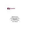
The sensor is able to adjust the temperature coefficients and store it in the controller
memory. There are up to 8 correction values (pair of data: temperature and signal ratio
<Stz>) could be written automatically or in manual mode. Temperature range from -40 to
+60⁰C is divided to equal intervals about 12.5⁰C. Each interval is used for responsible
operating temperature.
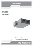
Automatic mode procedure:
Place the sensor in the chamber with nitrogen and send ZERO0 command. This
command is erase factory temperature coefficients and write the same data for
all memory cells.
Change the temperature in range -40 to +60⁰C with about 12.5⁰C interval. Stay
the sensor in each temperature interval for some minutes to fix temperature
fluctuation into the sensor. Write data by ZERO command for the current
temperature interval and signal ratio <Stz>.
Repeat ZERO command for all temperature intervals (see Fig. 10).
Fig. 10. Scheme of setting temperature coefficients in automatic mode.
Manual mode procedure:
It is possible to calculate temperature coefficients if the user fined the most preferred
temperature data and signal ratio <Stz>.
REV 0.7 Dated 14 April 2015
27
ESAT.413347.006 UM MIPEX-03-Х-XX-X.X USER MANUAL
Use ZERO XXXXX YYYYY command to set user data. Here XXXXX – temperature
data, YYYYY – signal ratio <Stz>. Data in the table are arranged automatically. The new
data is rewrite previous coefficients.
REV 0.7 Dated 14 April 2015
28
ESAT.413347.006 UM MIPEX-03-Х-XX-X.X USER MANUAL
Appendix D. Sensor zeroing and calibration.
1. Calibration is available using UART only.
2. Closing gas-sampling holes of the sensor impairs response time.
3. To achieve correct data during the tests, be sure there are no:
excessive force on sensor housing,
100% humidity (dewpoint),
out of specified range of environmental pressure,
fast temperature change (more than 0.6 ⁰C/min), dust (if dust
filter isn’t used),
sensor rate no more than 1Hz.
The setting of zero and calibration of the sensor is performed in the course of the
primary installation into a gas analyzer as well as annually during preparation to conducting
a check. In any cases the setting zero should be done before calibration.
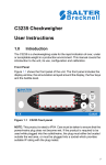
The devices given in Fig. 11 and the CGM are used in the course of conducting
operations.
The operations on setting zero and calibration of the sensor shall be carried out by a
qualified specialist outside of the explosion-hazardous zone at normal conditions in the
following sequence:
a) The sensor shall be connected in accordance with Fig. 11. Converter USB
should be connected to the sensor and PC.
b) Setting to zero use the following method. In 5 min after power supply the pure
nitrogen N2 СGM No.1 (depends on used calibration gas see the Table 9,
Table 10 or Table 11) is connected, in 1 min after СGM supply a command
ZERO2 of zero setting is supplied, the sensor readings should get set to zero
with respect to digital interface in accordance with Appendix C.
Additionally it is possible to set zero during the warm-up period. Switch
ON/OFF the sensor two times during the first minute. Sensor will starts zeroing
algorithm automatically after the third switch ON.
c) The СGM No.2 is connected, in 1 min after CGM supply a CALB AAAA
command is given, where AAAA is a value of CGM concentration (e.g. 1.98%
vol. – 0198). After that the value Conc1 – (scaled concentration) should get
established equal to a value assigned according to command CALB AAAA.
The scale coefficient shall be stored in the module memory up to the next
calibration.
d) The СGM No.3 is connected and the sensor readings are checked via digital
serial RS-232.
If the requirements to the sensor error are not fulfilled in accordance with Table 5, the
procedure of setting zero and calibration shall be repeated. In case of a repeated noncompliance of the sensor readings to the value of concentration of СGM No.3, the sensor is
subject to replacement and dispatching to the Manufacturer for repair.
REV 0.7 Dated 14 April 2015
29
ESAT.413347.006 UM MIPEX-03-Х-XX-X.X USER MANUAL
For MIPEX-03 with analog output see chapter 6.
Gas adapter
CGM
USB cable
PC
PC
USB converter
Fig. 11 Typical scheme of MIPEX-03 calibration
List of CGM used for checking IR gas sensors MIPEX-03
The recalculation to % of LEL shall be effected in accordance with the following
formula for concentration expressed in volume fraction, vol. %:
LFSCL
100 C
;%
C h
where
LFSCL is % LEL
С – component content in volume fraction, vol. %;
С(h) – LEL of component, % (constant);
С(h) = 4.4 % – for methane;
С(h) = 1.7 % – for propane.
Table 9. CGM used for CH4 calibration gas.
CGM
Nos
according
to text
Component
composition
Permissible
deviation
limits, vol. %
N2
Composition
of measured
component,
vol. %,
(% of LEL)
100
-
Limits of
permissible
error of
qualification,
vol. %
-
1
2
3
4
СН4 – N2
СН4 – N2
СН4 – N2
2,2 (50)
4,15 (94)
40
±0,25
±0,25
±2,5
±0,04
±0,04
±0,4
REV 0.7 Dated 14 April 2015
Number as
per State
Register or
Standard
designation
GOST
9392-74
3883-87
3883-87
3892-87
30
ESAT.413347.006 UM MIPEX-03-Х-XX-X.X USER MANUAL
Table 10. CGM used for C3H8 calibration gas.
CGM
Nos
according
to text
Component
composition
Permissible
deviation
limits, vol. %
N2
Composition
of measured
component,
vol. %,
(% of LEL)
100
-
Limits of
permissible
error of
qualification,
vol. %
-
1
2
3
4
С3Н8 – N2
С3Н8 – N2
С3Н8 – N2
0,85 (50)
1,6 (94)
3,40 (200)
±0,05
±0,1
±1,00
±0,015
±0,05
±0,5
Number as
per State
Register or
Standard
designation
GOST
9392-74
5328-90
EM 06.01.648
Table 11. CGM used for CO2 calibration gas.
CGM
Nos
according
to text
Component
composition
Permissible
deviation
limits, vol. %
N2
Composition
of measured
component,
vol. %,
(% of LEL)
100
-
Limits of
permissible
error of
qualification,
vol. %
-
1
2
3
СО2 – N2
СО2 – N2
1
2.5
±0,05
±0,1
±0,015
±0,05
REV 0.7 Dated 14 April 2015
Number as
per State
Register or
Standard
designation
GOST 939274
31
ESAT.413347.006 UM MIPEX-03-Х-XX-X.X USER MANUAL
Appendix E. Attaching the dust filter.
Tools required - tweezers, cloths.
Time required – 2… 3 min.
Perform this work in a well illuminated and well ventilated room.
After attaching the dust filter, perform the procedure of the sensor
zeroing (for details, see Appendix D for details).
To attach the dust filter, perform the following steps:
Wipe the sensor top surface with a cloth that is dampened with absolute alcohol.
For the MIPEX-03-X-XX-2.X sensors, perform the same operation on the side
surface.
Retrieve the teflon tape-bonded dust filters from packing.
Detach a filter from the teflon tape with tweezers.
Align the filter to the top surface center with tweezers, and then press on it.
For the MIPEX-03-X-XX-2.X sensors, perform the same operation on the side
surface.
After the dust filter was attached, zeroing procedure must be performed (see Appendix
D for details).
REV 0.7 Dated 14 April 2015
32