1
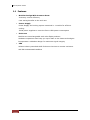
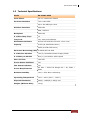
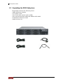
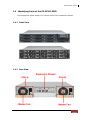
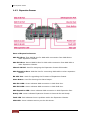
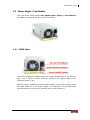
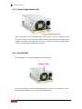
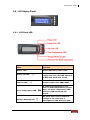
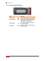
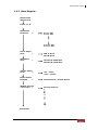
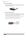
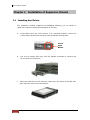
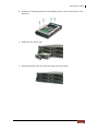
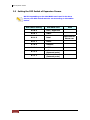
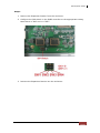
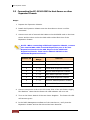
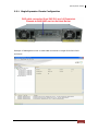
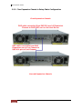
EP-2126J-S3S3 Epica Expansion Chassis User Manual Revision 1.2 P/N: PW0020000000304 Epica Expansion Chassis Table of Contents Chapter 1 Introduction ......................................................................................3 1.1 Features ......................................................................................................................................................... 4 1.2 Technical Specifications .......................................................................................................................... 5 1.3 Unpacking the JBOD Subsystem......................................................................................................... 6 1.4 Identifying Parts of the EP-2126J-S3S3............................................................................................ 7 1.4.1 Front View............................................................................................................................................ 7 1.4.2 Rear View ............................................................................................................................................. 7 1.4.3 Expansion Drawer ............................................................................................................................. 8 1.5 Power Supply / Fan Module ................................................................................................................. 9 1.5.1 PSFM Panel.......................................................................................................................................... 9 1.5.2 Power Supply Module LED ......................................................................................................... 10 1.5.3 Fan of PSFM...................................................................................................................................... 10 1.6 LCD Display Panel ................................................................................................................................... 11 1.6.1 LCD Panel LED ................................................................................................................................. 11 1.6.2 LCD Panel Function Buttons ...................................................................................................... 12 1.6.3 Menu Diagram ................................................................................................................................. 13 1.7 Drive Carrier Module.............................................................................................................................. 14 1.7.1 Disk Drive Status Indicators ....................................................................................................... 14 1.7.2 Drive Carrier Lock Indicator........................................................................................................ 15 Chapter 2 Installation of Expansion Chassis............................................ 16 2.1 Installing Hard Drives............................................................................................................................. 16 2.2 Setting the DIP Switch of Expansion Drawer............................................................................... 18 2.3 Connecting the EP-2126J-S3S3 to Host Server or other Expansion Chassis.................. 20 2.3.1 Single Expansion Chassis Configuration ............................................................................... 21 2.3.2 Two Expansion Chassis in Daisy-Chain Configuration .................................................... 22 Chapter 3 SAS JBOD Activate Zone Function ........................................... 24 2 User Manual Epica Expansion Chassis Chapter 1 Introduction The EP-2126J-S3S3 The Epica EP-2126J-S3S3 is Proware's most versatile SAS/SATA II Disk Expansion system, ideal for midrange and high capacity storage in Windows environment. Based on 3Gb SAS Channel host interfaces, the EP-2126J-S3S3 supports the choice of SAS (Serial Attached SCSI), and SATA II (Serial ATA) drive configurations to deliver a system bandwidth of up to 1,200 MB/sec. The ability to mix SAS and SATA drives allows the EP-2126J-S3S3 to be used for a range of applications that require different price/performance characteristics. Cost-effective SATA drives can be selected for capacity orientated storage such as disk-to-disk backup and storage of reference data. Higher specification SAS drives can be employed for I/O intensive applications including transactional databases. Hosting multiple tiers of data in an EP-2126J-S3S3 configuration gives organizations the flexibility to meet both their technical requirements and budgetary constraints with a single unified solution. User Manual 3 Epica Expansion Chassis 1.1 Features Modular Design With Common Parts Inventory control efficiency Cost-saving benefits to the end-user Power Supply Power Supply and cooling system contained in 1 module for efficient cooling 300W power supplies to meet the future HDD power consumption Enclosure Modules are interchangeable with other Epica products Hardware expansion slots keep you up-to-date on the latest technologies Incorporates a cableless design for maximum signal integrity SES Utilizes industry-standard SCSI Enclosure Services to monitor enclosure and disk environmental conditions 4 User Manual Epica Expansion Chassis 1.2 Technical Specifications Model EP-2126J-S3S3 Form Factor 2U 19" rackmount chassis Host Bus Interface Two 4 Lane SAS Up to 300 MB/s per Lane Disk Bus Interface 3Gb SAS SAS / SATA II Backplane 3Gb SAS # of Hot Swap Trays 12 Tray Lock Yes, with Lock Indicator Disk Status Indicator Access LED and Fail LED with 170°C view Capacity 4.8TB (at 400GB SAS drive) 24TB (at 2TB SATA drive) Enclosure Monitoring (SES) In Band SES via SAS # of PS/Fan Modules Two (2) Redundant Power Supply 300W # of Fans per Module One (1) per Module; Multi-speed Max. Air Flow 160 CFM Power Status Indicator Yes Fan Status Indicator Yes Power Requirements AC 90V ~ 264V Full Range 6A ~ 3A, 50Hz ~ 60Hz Relative Humidity 10% ~ 85% Non-condensing Operating Temperature 10°C ~ 40°C (50°F ~ 104°F ) Physical Dimension 460(L) x 482(W) x 88(H) mm Weight (Without Disk) 14 Kg User Manual 5 Epica Expansion Chassis 1.3 Unpacking the JBOD Subsystem The package contains the following items: • JBOD Expansion Chassis • Two power cords • One serial cable (phone-jack to DB9) • One external Mini SAS cable SFF-8088 to SFF-8088 • Installation Reference Guide • Spare screws, etc. 6 User Manual Epica Expansion Chassis 1.4 Identifying Parts of the EP-2126J-S3S3 The illustrations below identify the various parts of the expansion chassis. 1.4.1 Front View 1.4.2 Rear View User Manual 7 Epica Expansion Chassis 1.4.3 Expansion Drawer Parts of Expansion Drawer: SAS IN A Port: First SAS IN Port for SAS cable connection from SAS HBA or other Expansion Chassis. SAS IN B Port: Second SAS IN Port for SAS cable connection from SAS HBA or other Expansion Chassis. Chassis ID Dial: Used for assigning the Expansion Chassis ID Number. SAS Expansion Port: SAS Out Port for connecting SAS cable to other expansion chassis. RS-232 Port: Used for upgrading the Firmware of Expansion Chassis. Mute Button: Used for silencing the alarm beeper. SAS IN A LED: Green indicates SAS connection in SAS IN A Port. SAS IN B LED: Green indicates SAS connection in SAS IN B Port. SAS Expansion LED: Green indicates SAS connection in SAS Expansion Port. Ready LED: Green indicates Expansion Chassis is Powered On and Ready. Fault LED: Red indicates there is problem within the Expansion Chassis. HDD LED: Green indicates activity on the disk drives. 8 User Manual Epica Expansion Chassis 1.5 Power Supply / Fan Module Every EP-2126J-S3S3 contains two 300W Power Supply / Fan Modules. All PSFMs are inserted into the rear of the chassis. 1.5.1 PSFM Panel The Power Supply/Fan Module panel has: Power On/Off Switch, the AC Inlet Plug, and a Power On/Fail Indicator showing the Power Status LED, indicating ready or fail. Each fan within a PSFM is powered independently of the power supply within the same PSFM. So if the power supply of a PSFM fails, the fan associated with that PSFM will continue to operate and cool the enclosure. User Manual 9 Epica Expansion Chassis 1.5.2 Power Supply Module LED When the power cord connected from main power source is inserted to the AC Power Inlet, the power status LED becomes RED. When the switch of the PSFM is turned on, the LED will turn GREEN. When the Power On/Fail LED is GREEN, the PSFM is functioning normally. 1.5.3 Fan of PSFM Each PSFM has 1 fan located beside the PSFM panel. Master Fan In the LCD display, Fan of Power Supply Unit A is shown as “MF/PSU-A” and Fan of Power Supply Unit B is shown as “MF/PSU-B”. 10 User Manual Epica Expansion Chassis 1.6 LCD Display Panel 1.6.1 LCD Panel LED Parts Function Power LED Green indicates power is ON. Power Fail LED Fan Fail LED If one of the redundant power supply unit fails, this LED will turn to RED and alarm will sound. Turn RED when fan 1 or 2 fails, or speed is lower than 2000 RPM. Over Temperature LED If system temperature is over 70oC or disk temperatures exceed 55oC, the Over Temperature LED will turn RED and alarm will sound. Voltage Warning LED An alarm will sound if detected voltage in the controller is abnormal and LED will turn RED. User Manual 11 Epica Expansion Chassis 1.6.2 LCD Panel Function Buttons Parts Function Up and Down Arrow buttons Use the Up or Down arrow keys to go through the information on the LCD screen. This is also used to move between each menu. Select button This is used to enter the option you have selected. Exit button 12 User Manual EXIT Press this button to return to the previous menu. Epica Expansion Chassis 1.6.3 Menu Diagram Model-Name Chassis ID:0 F/W V 1.1.7J Disk Status ID:001-12 > S 1*0* 33C S 2*0* 32C : S 11*0* 31C S 12*0* 30C Power Status Good > PSU-A: Good PSU-B: Good FAN Status Good > MF/PSU-A: 3409 RPM MF/PSU-B: 3479 RPM Voltage Status Good > Buzzer Status Disabled > SPINUP Interval 1 Second(s) > +5V : 5.23V +12V : 12.33V Disable Buzzer / Enable Buzzer Seconds Interval 1 2 : 20 Zone Status User Manual 13 Epica Expansion Chassis 1.7 Drive Carrier Module The Drive Carrier Module houses a 3.5 inch hard disk drive. It is designed for maximum airflow and incorporates a carrier locking mechanism to prevent unauthorized access to the HDD. 1.7.1 Disk Drive Status Indicators Every Drive Carrier has 2 status indicator lights. One indicator light is used for Power On/Error. When this light is GREEN the power is on and everything is functioning normally. When the Power On/Error light is RED, then an error has happened that requires the user’s attention. The other status indicator light is the hard disk drive access light. When the hard disk drive is being accessed, this light will flash BLUE. In addition, both indicator lights are viewable within a 170° arc. Disk Activity Indicator Disk Status Indicator 14 User Manual Epica Expansion Chassis 1.7.2 Drive Carrier Lock Indicator Every Drive Carrier is lockable and is fitted with a lock indicator to indicate whether or not the carrier is locked into the chassis or not. Each carrier is also fitted with an ergonomic handle for easy carrier removal. Drive Carrier is unlocked When the Lock Groove is vertical, then the Drive Carrier is unlocked. Drive Carrier is locked When the Lock Groove is horizontal, this indicates that the Drive Carrier is locked. Lock and unlock the Drive Carriers by using a flat-head screw driver. User Manual 15 Epica Expansion Chassis Chapter 2 Installation of Expansion Chassis 2.1 Installing Hard Drives The expansion chassis supports hot-swapping allowing you to install or replace a hard drive while the subsystem is running. a. Press Make sure the Lock Groove is in unlocked position. Press the Carrier Open button and the Drive Carrier handle will flip open. Carrier Open Button b. Pull out an empty disk tray. Pull the handle outwards to remove the carrier from the enclosure. c. Place the hard drive in the disk tray. Make sure the holes of the disk tray align with the holes of the hard drive. 16 User Manual Epica Expansion Chassis d. Install the mounting screws on the bottom part to secure the drive in the disk tray. e. Slide the tray into a slot. f. Close the handle until you hear the latch click into place. User Manual 17 Epica Expansion Chassis 2.2 Setting the DIP Switch of Expansion Drawer NOTE: Depending on the SAS RAID card used in the Host Server, the DIP switch must be set according to the tables below. 18 DIP Switch Setting SAS RAID Card 0000 Dell / HighPoint 0001 AMCC 0010 Intel 0011 Areca 0100 Adaptec 0101 ATTO 0110 LSI (External ports) 0111 LSI (Internal ports) User Manual Note Reserved for future use. Epica Expansion Chassis Steps: 1. Remove the Expansion Drawer from the enclosure. 2. Configure the DIP Switch in the JBOD controller to the appropriate setting. Note that 0 is “ON” and 1 is “OFF”. 3. Reinsert the Expansion Drawer into the enclosure. User Manual 19 Epica Expansion Chassis 2.3 Connecting the EP-2126J-S3S3 to Host Server or other Expansion Chassis Steps: 1. Prepare the Expansion Chassis. 2. Install the Expansion Chassis near the Host Server where it will be connected. 3. Connect one end of external SAS cable to the SAS RAID card on the Host Server and the other end to the SAS cable to SAS IN A Port of the Expansion Chassis. NOTE: When connecting additional Expansion Chassis, connect the external SAS cable from SAS Expansion port of the last Expansion Chassis to the SAS IN port of the additional Expansion Chassis. Then set the Chassis ID Dial on the additional Expansion Chassis. Chassis ID Disk ID Range 0 1 ~ 12 First JBOD Expansion Chassis 1 1 ~ 12 Second JBOD Expansion Chassis 2 1 ~ 12 Third JBOD Expansion Chassis 3 1 ~ 12 Fourth JBOD Expansion Chassis 4 1 ~ 12 Fifth JBOD Expansion Chassis 5 1 ~ 12 Sixth JBOD Expansion Chassis 6 1 ~ 12 Seventh JBOD Expansion Chassis 7 1 ~ 12 Eighth JBOD Expansion Chassis Used for 4. Connect two power cords to the AC Power Inlet of the two Power Supply Fan Modules. Note that the Power-On LED indicator will turn red. 5. Turn on the Power Switch of the two Power Supplies. The Power-On LED will become green. 6. In the RAID Management software of the Host Server, verify that the Expansion Chassis and its disk drives has been detected. 20 User Manual Epica Expansion Chassis 2.3.1 Single Expansion Chassis Configuration Example of Management GUI on SAS HBA connected to single EP-2126J-S3S3 enclosure: User Manual 21 Epica Expansion Chassis 2.3.2 Two Expansion Chassis in Daisy-Chain Configuration First Expansion Chassis Second Expansion Chassis 22 User Manual Epica Expansion Chassis Example of Management GUI on SAS HBA connected to two EP-2126J-S3S3 enclosures in daisy-chain configuration: User Manual 23 Epica Expansion Chassis Chapter 3 SAS JBOD Activate Zone Function If Zone Function is activated, you cannot connect other JBOD Expansion Chassis. In Zoning, the Disk will be divided into two separate groups. In 12-bay, the first group will be slot 1-6 can only be seen on Input 1. The 2nd group will be slot 7-12 can only be seen on Input 2. FUNCTION COMMAND Get Zoning Status phyzone get all Activate Zoning phyzone set activate all Clear Zoning phyzone clr all Get Zoning Status: 1. phyzone get all: Used RS-232 Port (Phone jack to DB9) link SAS JBOD, in command line please input “phyzone get all”, than press “enter”. 24 User Manual Epica Expansion Chassis Activate Zoning: 1. phyzone set activate all: Used RS-232 Port (Phone jack to DB9) link SAS JBOD, in command line input “phyzone set activate all”, than press “enter”. User Manual 25 Epica Expansion Chassis 2. phyzone get all: Used RS-232 Port (Phone jack to DB9) link SAS JBOD, in command line please input “phyzone get all”, than press “enter”. Note: LCD Panel will showing “Zone Status: On”. 26 User Manual Epica Expansion Chassis Clear Zoning: 1. phyzone clr all Used RS-232 Port (Phone jack to DB9) link SAS JBOD, in command line input “phyzone clr all”, than press “enter”. User Manual 27 Epica Expansion Chassis 2. phyzone get all: Used RS-232 Port (Phone jack to DB9) link SAS JBOD, in command line please input “phyzone get all”, than press “enter”. Note: LCD Panel will showing “Zone Status: Off”. 28 User Manual