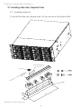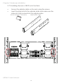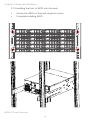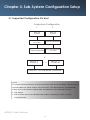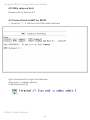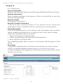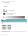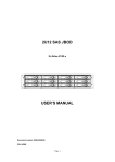
1
J4024-01
SAS/SATA JBOD SERIES
User's Manual
D/N:MAN-00305-B
P/N: H884JKC000-00010-?
CONTENTS
PREFACE�������������������������������������������������������������������������������������������������������� i
SAFETY INSTRUCTIONS��������������������������������������������������������������������������������� ii
Chapter 1. Prodcut Introduction�������������������������������������������������������������1
1.1 Box Content������������������������������������������������������������������������������������������������������ 1
1.2 Specifications��������������������������������������������������������������������������������������������������� 2
1.3 General Information����������������������������������������������������������������������������������������� 3
1.4 SCSI Enclosure Services - 2 (SES-2)����������������������������������������������������������������� 6
Chapter 2. Hardware Installation������������������������������������������������������������7
2.1 Removing and Installing Top Cover��������������������������������������������������������������� 7
2.2 Removing/Installing a Drive Tray/ Hard Drive/ Drive Slot Map�������������������� 8
2.3 Removing and Installing a PSU Module������������������������������������������������������� 10
2.4 Removing and Installing a Fan Module������������������������������������������������������� 11
2.5 Removing and Installing External Expander Module���������������������������������� 12
2.6 Removing and Installing the HDD backplane Module������������������������������ 13
2.7 Installing Slide Rail /Adjuster Plate��������������������������������������������������������������� 14
Chapter 3. Sub-System Configuration Setup���������������������������������������17
3.1 Supported Configuration On Host����������������������������������������������������������������� 17
3.2 Utility Set up on Host��������������������������������������������������������������������������������������� 18
3.3 Connect Host to JBOD via RS232������������������������������������������������������������������ 21
3.4 Configure command Line Interface Operation������������������������������������������ 22
3.5 Power on/off the enclosure via RS232���������������������������������������������������������� 49
Chapter 4. BMC Configuration and Settings����������������������������������������51
4.1 Sensor’s location for Fan & Temperature����������������������������������������������������� 51
4.2 Utility setup on Host���������������������������������������������������������������������������������������� 52
4.3 Connect Host to BMC by RS232�������������������������������������������������������������������� 52
4.4 BMC LED signal����������������������������������������������������������������������������������������������� 56
4.5 Web UI������������������������������������������������������������������������������������������������������������� 57
4.5.1 Dashboard��������������������������������������������������������������������������������������������������� 57
4.6 Firmware Update�������������������������������������������������������������������������������������������� 76
4.7 Expander firmware update��������������������������������������������������������������������������� 81
4.8 Firmware safety mode����������������������������������������������������������������������������������� 84
Chapter 5. Technical Support���������������������������������������������������������������89
contents
Copyright © 2015 AIC, Inc. All Rights Reserved.
This document contains proprietary information about
AIC products and is not to be disclosed or used except in
accordance with applicable agreements.
PREFACE
• Copyright
No part of this publication may be reproduced, stored in a retrieval system,
or transmitted in any form or by any means, electronic, mechanical, photostatic, recording or otherwise, without the prior written consent of the
manufacturer.
• Trademarks
All products and trade names used in this document are trademarks or
registered trademarks of their respective holders.
• Changes
The material in this document is for information purposes only and is subject
to change without notice.
• Warning
1. A shielded-type power cord is required in order to meet FCC emission
limits and also to prevent interference to the nearby radio and television
reception. It is essential that only the supplied power cord be used.
2. Use only shielded cables to connect I/O devices to this equipment.
3. You are cautioned that changes or modifications not expressly approved
by the party responsible for compliance could void your authority to
operate the equipment.
• Disclaimer
AIC shall not be liable for technical or editorial errors or omissions
contained herein. The information provided is provided "as is" without
warranty of any kind. To the extent permitted by law, neither AIC or its
affiliates, subcontractors or suppliers will be liable for incidental, special or
consequential damages including downtime cost; lost profits; damages
relating to the procurement of substitute products or services; or damages
for loss of data, or software restoration. The information in this document is
subject to change without notice.
i
SAFETY INSTRUCTIONS
• Before getting started, please read the following important cautions:
• All cautions and warnings on the equipment or in the manuals should be
noted.
• Most electronic components are sensitive to electrical static discharge.
Therefore, be sure to ground yourself at all times when installing the
internal components.
• Use a grounding wrist strap and place all electronic components in
static-shielded devices. Grounding wrist straps can be purchased in any
electronic supply store.
• Be sure to turn off the power and then disconnect the power cords from
your system before performing any installation or servicing. A sudden
surge of power could damage sensitive electronic components.
• Do not open the system’s top cover. If opening the cover for
maintenance is a must, only a trained technician should do so.
Integrated circuits on computer boards are sensitive to static electricity.
Before handling a board or integrated circuit, touch an unpainted
portion of the system unit chassis for a few seconds. This will help to
discharge any static electricity on your body.
• Place this equipment on a stable surface when install. A drop or fall
could cause injury.
• Please keep this equipment away from humidity.
• Carefully mount the equipment into the rack, in such manner, that it
won’t be hazardous due to uneven mechanical loading.
• This equipment is to be installed for operation in an environment with
maximum ambient temperature below 35°C.
• The openings on the enclosure are for air convection to protect the
equipment from overheating. DO NOT COVER THE OPENINGS.
• Never pour any liquid into ventilation openings. This could cause fire or
electrical shock.
• Make sure the voltage of the power source is within the specification
on the label when connecting the equipment to the power outlet. The
current load and output power of loads shall be within the specification.
• This equipment must be connected to reliable grounding before using.
Pay special attention to power supplied other than direct connections,
e.g. using of power strips.
• Place the power cord out of the way of foot traffic. Do not place
anything over the power cord. The power cord must be rated for the
ii
• product, voltage and current marked on the product’s electrical ratings
label. The voltage and current rating of the cord should be greater than the
voltage and current rating marked on the product.
• If the equipment is not used for a long time, disconnect the equipment from
mains to avoid being damaged by transient over-voltage.
• Never open the equipment. For safety reasons, only qualified service
personnel should open the equipment.
• If one of the following situations arise, the equipment should be checked by
service personnel:
1. The power cord or plug is damaged.
2. Liquid has penetrated the equipment.
3. The equipment has been exposed to moisture.
4. The equipment does not work well or will not work according to its user
manual.
5. The equipment has been dropped and/or damaged.
6. The equipment has obvious signs of breakage.
7. Please disconnect this equipment from the AC outlet before cleaning.
Do not use liquid or detergent for cleaning. The use of a moisture sheet or
cloth is recommended for cleaning.
• Module and drive bays must not be empty! They must have a dummy cover.
Product features and specifications are subject to change without notice.
CAUTION :
risk of explosion if battery is replaced by an incorrect type.
dispose of used batteries according to the instructions.
After performing any installation or servicing, make sure the
enclosure are lock and screw in position, turn on the power.
iii
Chapter 1 Product Introduction
Chapter 1. Prodcut Introduction
1.1 Box Content
Before removing the subsystem from the shipping carton, visually inspect the
physical condition of the shipping carton. Exterior damage to the shipping
carton may indicate that the contents of the carton are damaged. If any
damage is found, do not remove the components; contact the dealer where
the subsystem was purchased for further instructions. Before continuing, first
unpack the subsystem and verify that the contents of the shipping carton are
all there and in good condition.
• Enclosure( Power supply, fan, 24 HDD tray included)
• RS232 cablex 1pcs
• Power cord x 2pcs
• Screws kit x 1set
• Mounting Optional
or
• Slide Rail x 1set
• Adjuster Plate x 1set
If any items are missing, please contact your authorized reseller or sales representative.
J4024-01 User's Manual
1
Chapter 1 Product Introduction
1.2 Specifications
J4024-01 User's Manual
2
Chapter 1 Product Introduction
1.3 General Information
J4024-01 is a 4U rackmount chassis with 24 x 3.5”HDD hot swap bay and
dual expand module JBOD, which is a high performance, high density,
scalable storage product. The J4024-01 JBOD supports T10 zoning function
and can be shared by up to 6 servers.
• Front Panel
Supports hot-swappable 24 x 3.5” HDDs
LED In dicator and Switch
J4024-01 User's Manual
3
Chapter 1 Product Introduction
• Rear Expender Panel
BMC LAN port(option)
BMC console port
Debug port
SFF 8644 wide port
BMC LAN port(option)
BMC console port
SFF 8644 wide port
2 Dual Expander (Primary & Secondary)
J4024-01 User's Manual
4
Console port
Chapter 1 Product Introduction
• Rear Panel
J4024-01 User's Manual
5
Chapter 1 Product Introduction
1.4 SCSI Enclosure Services - 2 (SES-2)
To ensure J4024-01 can work properly and provide high performance,
durability. J4024-01 has implemented SCSI Enclosure Services-2 to
monitor the status of power supply, system cooling fan and working
temperature. It also has the indicators to deliver the status of fail devices
such as power supply or cooling fan. You can get the information
directly from the front indicators to know how your enclosure works.
For detailed information, please visit http://www.t10.org
If you are a member of the T10 working group, the Standard which
controlled by T10 technical committee, could be found at
http://www.t10.org/cgi-bin/ac.pl?t=f&f=ses2r19a.pdf
1.4.1 SES pages supported are listed below
00h -list of supported diagnostic pages
01h -SES -configuration
02h -SES -enclosure control / enclosure status
07h -SES -element descriptor
0Ah -SES -additional element
0Eh -SES -download microcode control / SES download
microcode status
1.4.2 SES elements supported are listed below.
02h -power-supply
03h -cooling
04h -temperature-sensor
0Eh -enclosure
12h -Voltage
17h -array device
J4024-01 User's Manual
6
Chapter 2 Hardware Installation
Chapter 2. Hardware Installation
This chapter provides detailed instructions on hardware installation.
2.1 Removing and Installing Top Cover
Loosen 2 screws on top cover. Take it out of the enclosure.
J4024-01 User's Manual
7
Chapter 2 Hardware Installation
2.2 Removing/Installing a Drive Tray/ Hard Drive/ Drive Slot Map
2.2.1 Removing a Disk Drive
Release a drive tray by pressing the unlock button and pinching the lock
lever slightly and pulling out the drive tray.
2.2.2 Installing a 3.5'' Disk Drive
Directly place HDD into tool-less HDD tray
until it snaps. Please check if the screw
holes on HDD match the dimples on HDD
tray.
HDD can also be screwed on HDD tray by
fastening two screws as picture
showed.
J4024-01 User's Manual
8
Chapter 2 Hardware Installation
2.2.3 Installing a Hard Disk Drive Tray
Insert the drive carrier into its bay. Push the tray lever until it clicks.
Make sure the drive tray is correctly secured in place when its front edge
aligns with the bay edge.
2.2.4 Drive Slot Map
The drive slot map follows.
J4024-01 User's Manual
9
Chapter 2 Hardware Installation
2.3 Removing and Installing a PSU Module
2.3.1 Removing a PSU module
•
Remove power cables connected to the PSU module.
•
Allow a minute for fan to spin down.
•
Pushing the latch then hold the tray handle tab. Then pull the PSU
module gently until it slides out of the JBOD.
2.3.2 Installing a PSU Module
•
Slide in PSU module.
•
Make sure the latch on the module is fully hooked onto the PSU
housing.
J4024-01 User's Manual
10
Chapter 2 Hardware Installation
2.4 Removing and Installing a Fan Module
2.4.1 Removing a Fan module
•
Loosen the thumb screws on each sides in front of fan module.
•
Hold the fan module from both sides.
•
Pull the fan module gently and firmly until it clears the enclosure
chassis.
2.4.2Installing a Fan Module
•
Align the fan module with the opening in the enclosure.
•
Insert the fan module into JBOD.
J4024-01 User's Manual
11
Chapter 2 Hardware Installation
2.5 Removing and Installing External Expander Module
2.5.1 Removing an expander module
•
Loosen the thumb screw to release expander tray lever.
•
Hold the lever to pull the expander out of JBOD.
2.5.2 Installing an expander module
•
Align the expander module with the opening in front of the enclosure,
and insert it into the enclosure firmly.
•
Close the lever and secure the retaining screw.
J4024-01 User's Manual
12
Chapter 2 Hardware Installation
2.6 Removing and Installing the HDD backplane Module
2.6.1 Removing a HDD backplane module
•
Unscrew 8pcs screws in the middle side of JBOD to release the HDD
backplane module. (2* top side 2* bottom side *3 both side)
•
Hold the backplane module to pull the backplane module out of
JBOD.
2.6.2 Installing a HDD backplane module
•
Slide the HDD backplane module into JBOD.
•
Secure the HDD backplane module onto the JBOD using the screws.
J4024-01 User's Manual
13
Chapter 2 Hardware Installation
2.7 Installing Slide Rail /Adjuster Plate
2.7.1 Installing slide rail
To install the slide rail, please refer to the manual in the slide rail kit.
7.Slide Rail Installation
User’s Manual
Screws kit
5
6
3
2
1
4
7
4
0
55
Th
pu
e
slid
o
ti
ec
ir
ed
f
no
he
ll t
ut
lo
rai
0
0
1
J4024-01 User's Manual
14
Chapter 2 Hardware Installation
2.7.2 Installing the rear of JBOD onto the Rack
•
•
Secure the adjuster plate on the rack using the screws.
Insert the slide rail into the adjuster plate and make sure the
slide rail is fully hooked into the adjuster plate.
M4 X 6L screws kit * 1sets (10pcs)
Adjuster plate *2 sets
J4024-01 User's Manual
15
Chapter 2 Hardware Installation
2.7.3 Installing the front of JBOD onto the rack
•
•
Secure the JBOD on the rack using the screws.
Complete installing JBOD.
J4024-01 User's Manual
16
Chapter 3 Sub-System configuration Setup
Chapter 3. Sub-System Configuration Setup
3.1 Supported Configuration On Host
Supported Configuration
1.
2.
Host
Host
Each AIC Expander
Controller
Other Expander
Other Expander
Each AIC Expander
Controller
3.
Host-1
......
Host-n
Each AIC 12G Expander Controller
note :
To have multiple host access support (the host number can be up to
the number of wide ports on each AIC 12G Expander Controller),
only the following drives are supported for shared access:
1. SAS drive
2. SATA drive with an interposer which provides SATA-to-SAS
conversion
J4024-01 User's Manual
17
Chapter 3 Sub-System configuration Setup
3.2 Utility Set up on Host
Step 1: Set up host RS232 connection
Set up RS232 connection application into your host as
shown in the example process below.
For example:
OS: Microsoft Windows Server 2008
RS232 connection application: Hyperterminal
Step 2: Install HyperTrm.exe
J4024-01 User's Manual
18
Chapter 3 Sub-System configuration Setup
Step 3: Enter a new name for the icon in the field below and click OK.
Step 4: Connect by using selecting an option in the drop down menu
circled in red below (we selected COM2 in this example) and click OK.
J4024-01 User's Manual
19
Chapter 3 Sub-System configuration Setup
Step 5: For “Bits per second”, select 38400. For “Flow control”, select: None.
Click OK when you have finished your selections.
Properties
Port Setting
Bits per second:
Data bits:
Parity:
None
Stop bits:
Flow control:
None
Restore Defaults
Cancel
OK
Apply
Step 6 : Set up is complete. The diagram below depicts what screen should
displayed.
J4024-01 User's Manual
20
Chapter 3 Sub-System configuration Setup
3.3 Connect Host to JBOD via RS232
Use a RS-232 DB9 cable to connect the console port of JBOD with host's PC
COM port (see figures below for DB9 RS-232 cable and SAS expander COM
port).
J4024-01 User's Manual
21
Chapter 3 Sub-System configuration Setup
3.4 Configure command Line Interface Operation
3.4.1 How to enable/disable T10 zoning
The default T10 zoning configuration is off.
(A) Check the current zoning state
cmd> phyzone state
Zoning is OFF
(B) Enable zoning
cmd> phyzone on
cmd >
(C) Disable zoning
cmd >
cmd >
cmd> phyzone off
cmd >
cmd >
cmd >
cmd >
cmd >
cmd >
cmd >
cmd >
cmd >phyzone state
Zoning is OFF
cmd >_
cmd >
cmd >
cmd >
cmd >
cmd >
cmd >
cmd >
cmd >
cmd >
cmd >
cmd >
cmd >phyzone on
Succeeded to enable zoning
cmd >_
cmd >
cmd >
cmd >
cmd >
cmd >
cmd >
cmd >
cmd >
cmd >
cmd >
cmd >
cmd >phyzone off
Succeeded to dissable zoning
cmd >_
J4024-01 User's Manual
22
Chapter 3 Sub-System configuration Setup
3.4.2 How to configure T10 zoning
After enabling T10 zoning, five predefined groups are Group1, Group8,
Group9, Group10, and Group11.
Each PHY should be in one of the five groups, and all PHYs in a wide port
should be in the same group.
Each PHY in Group1 can access any PHY in other groups, and vice versa.
Each PHY in Group8 cannot access any PHY in Group9, and vice versa.
The command syntax is "phyzone phy_index group". The following example
shows how to setup one drive accessed only the first port and another
drive accessed only by the second port.
The configuration for the example is
(A) PHY0 - PHY3 for the first wide port
(B) PHY4 - PHY7 for the second wide port
(C) PHY12 - PHY35 for drive
Step 1: Read the current group for PHY4
cmd> phyzone 4
Phy 4 for Zone Group 1
Step 2: Assign the second port (PHY4 - PHY7) for Group9
cmd> phyzone 4 9
cmd> phyzone 5 9
cmd> phyzone 6 9
cmd> phyzone 7 9
Step 3: Assign the first port (PHY0 - PHY3) for Group8
cmd> phyzone 0 8
cmd> phyzone 1 8
cmd> phyzone 2 8
cmd> phyzone 3 8
Step 4: Assign the drive on PHY12 to be accessed only by the first port
instead of the second port
cmd> phyzone 12 8
Step 5: Assign the drive on PHY13 to be accessed only by the second port
instead of the first port
cmd> phyzone 13 9
Step 6: Reset
J4024-01 User's Manual
23
Chapter 3 Sub-System configuration Setup
cmd >
cmd >
cmd >
cmd >
cmd >
cmd >
cmd >
cmd >
cmd >
cmd >
cmd >
cmd >phyzone 4
Phy 4 for Zone Group 1
cmd >_
cmd >phyzone 4 9
Succeeded to set zone group for the phy
cmd >phyzone 5 9
Succeeded to set zone group for the phy
cmd >phyzone 6 9
Succeeded to set zone group for the phy
cmd >phyzone 7 9
Succeeded to set zone group for the phy
cmd >
cmd >
cmd >
cmd >
cmd >_
cmd >phyzone 12 8
Succeeded to set zone group for the phy
cmd >phyzone 13 9
Succeeded to set zone group for the phy
cmd >
cmd >
cmd >
cmd >
cmd >
cmd >
cmd >
cmd >
cmd >
cmd >_
cmd >phyzone 13 9
Succeeded to set zone group for the phy
cmd >
cmd >
cmd >
cmd >
cmd >
cmd >
cmd >
cmd >
cmd >
cmd >reset
_
J4024-01 User's Manual
24
Chapter 3 Sub-System configuration Setup
3.4.3 How to get all revisions in AIC SAS 12G Expander
(A) Expander firmware revision
cmd> rev
(B) Expander configuration revision
cmd> showmfg
(C) MCU firmware for managing sensors
cmd> sensor
cmd >rev
===================================================================
Firmware Revision Information;===================================================================
Active Firmware:
Revision:1.12.1.4
Version Name: AIC SAS3xFW-01.12.01-04
Firmware Family: 0 OemFamily:0
Fast Boot: Yes Image Address: 0x10000000
cmd >showmfg
===================================================================
Manufacturing Image Version Information:===================================================================
Mfg Revision:
1.1.0.4
Product Name:
SAS3_HOTSWAP
Platform Name:
AIC 12G
cmd >_
cmd >sensor
==ENCLOSURE STATUS==========================================================
Total fan number
:2
System Fan-0 speed
: 10888 RPM
System Fan-1 speed
: 10971 RPM
System PWN-0
: 82%
Expander Temperature
: 76 Celsius degree
Sytem Temperature-0
: 33 Celsius degree
T1
: 20 Celsius degree
T2
: 50 Celsius degree
TC
: 55 Celsius degree
Voltage Sensor 0.9V
: 0.93V
Voltage Sensor 1.8V
: 1.80V
Pomer-0
NCU ID
Current Model
: good
: 2U24SAS3swap
: 2U24SAS3swap
Alarm-system
Alarm-temperature
Alarm-fan
Alarm-global
Buzzer-state
Buzzer-mute
: off
: off
: off
: off
: off
: off
MCU firmware version
:1.2
===========================================================================
cmd >_
J4024-01 User's Manual
25
Chapter 3 Sub-System configuration Setup
3.4.4 How to configure temperature sensor
Four temperature settings in Celsius are T1, T2, warning threshold, and alarm
(critical) threshold.
(A) Get the current temperature settings
cmd> temperature
Temperature in Celsius (t1=20 C, t2=55 C, warning=50 C, alarm=55 C)
(B) Set temperature with new T1=18 C, T2=52 C, warning threshold=48 C, and
alarm threshold=54 C. The new setting will take effect after reset.
cmd> temperature 18 52 48 54
cmd> reset
(C) We also take expander temperature into consideration, and the
temperature parameters for expander are fixed. Expander temperature
parameters: T1=40, T2=86 (max 115*0.75) ,and no warning or alarm.
The smart fan feature will use the highest PWM output which is calculated from
system and expander temperature parameters.
cmd >
cmd >temperature
Temperature in Celsius(t1=20 C, t2=50 C, Warning=50 C, alarm=55 C)
cmd >
cmd >
cmd >
cmd >_
cmd >
cmd >
cmd >
cmd >
cmd >
cmd >temperature 18 52 48 54
Succeeded to update temperature
cmd >reset_
J4024-01 User's Manual
26
Chapter 3 Sub-System configuration Setup
3.4.5 How to configure enclosure address
(A) Get the current enclosure address
cmd> enclosure_addr
Enclosure Address: 0x500605B0000272BF
(B) Set the enclosure address with 0x500605B0000272BF. The new setting will
take effect after reset.
cmd> enclosure_addr 500605B0000272BF
cmd> reset
cmd >
cmd >
cmd >
cmd >
cmd >
cmd >
cmd >
cmd >
cmd >
cmd >
cmd >enclosure_addr
Enclosure Address: 0x50015B21682C7F3F
cmd >
cmd >
cmd >
cmd >
cmd >
cmd >
cmd >
cmd >
cmd >
cmd >
cmd >
cmd >enclosure_addr 500605B0000272BF
Succeeded to set Enclosure address
cmd >reset_
J4024-01 User's Manual
27
Chapter 3 Sub-System configuration Setup
3.4.6 How to configure standby timer for all disk drives
This feature is applicable for SAS/SATA drives. Standby timer is in units of
minutes. Setting standby timer with 0 minute disables this feature.
(A) Get current standby timer
cmd> standby_timer
Standby Timer : 0 minutes
(B) Set the standby timer with 10 minutes. The new setting will take effect
after reset.
cmd> standby_timer 10
cmd> reset
cmd >
cmd >
cmd >
cmd >
cmd >
cmd >
cmd >
cmd >
cmd >
cmd >
cmd >standby_timer
Standby Timer : 0 minutes
cmd >_
cmd >
cmd >
cmd >
cmd >
cmd >
cmd >
cmd >
cmd >
cmd >standby_timer 10
Succeeded to set standby timer
cmd >reset_
J4024-01 User's Manual
28
Chapter 3 Sub-System configuration Setup
3.4.7 How to configure wide port checker
This feature is applicable for SAS drives instead of SATA drives. If there is
no connection with any active SAS initiator by checking all wide ports,
AIC Expander Controller stops all attached SAS drives to save power
consumption of SAS drives. Otherwise, AIC Expander Controller starts all
attached SAS drives to provide drive access service to any active SAS
initiator.
(A) Get the current state of wide port checker
cmd> check_wide_port
Checking wide port is OFF
(B) Enable checking wide port. The new setting will take effect after reset.
cmd> check_wide_port on
cmd> reset
(C) Disable checking wide port. The new setting will take effect after reset.
cmd> check_wide_port off
cmd> reset
J4024-01 User's Manual
29
Chapter 3 Sub-System configuration Setup
cmd >
cmd >
cmd >
cmd >
cmd >
cmd >
cmd >
cmd >
cmd >
cmd >
cmd >check_wide_port
Checking wide port is OFF
cmd >_
cmd >
cmd >
cmd >
cmd >
cmd >
cmd >
cmd >
cmd >
cmd >check_wide_port on
Succeeded to configure checking wide port
cmd >reset_
cmd >
cmd >
cmd >
cmd >
cmd >
cmd >
cmd >
cmd >
cmd >check_wide_port off
Succeeded to configure checking wide port
cmd >reset_
J4024-01 User's Manual
30
Chapter 3 Sub-System configuration Setup
3.4.8 How to configure serial number
(A) Get the current serial number
cmd> serial_number
Expander number: 421-12021704510010 or Expander number: 42112021704510010 Enclosure number: 526-12071100500088
(B) Only set Expander serial number with 421-12021704510010.
cmd> serial_number 421-12021704510010
(C) Set both of Expander serial number (421-12021704510010) and Enclosure
serial number (526-12071100500088).
cmd> serial_number 421-12021704510010 526-12071100500088
cmd >
cmd >
cmd >
cmd >
cmd >
cmd >
cmd >
cmd >
cmd >
cmd >
cmd >serial_number 421-12021704510010 526-12071100500088_
J4024-01 User's Manual
31
Chapter 3 Sub-System configuration Setup
3.4.9 How to turn on/off the power of a drive slot
The "DEVICE OFF" for a drive slot is defined in the bit4, byte3 of the "Array
Device Slot control element" in the SES-3 specification. Set the bit to turn off
a slot power, and vice versa. Please install a software package "sg3_utils"
on your host computer, and have a SAS HBA and a cable to connect your
host with the expander. We use Linux for example.
(A) Show the device for AIC Expander Controller (canister)
$ sg_map -i
/dev/sg2 AIC 12G 2U24SAS3swap 0c01
(B) Get the current state of a slot power. The "Device off=0" means the slot
power is on.
$ sg_ses --page=2 /dev/sg2
Element 0 descriptor:
App client bypass B=0, Fault sensed=0, Fault reqstd=0, Device off=0
(C) Get the descriptor of a slot power
$ sg_ses --page=7 /dev/sg2
Element 0 descriptor: Disk001
(D) Turn off a slot power
$ sg_ses --descriptor=Disk001 --set=3:4:1 /dev/sg2
(E) Turn on a slot power
$ sg_ses --descriptor=Disk001 --clear=3:4:1 /dev/sg2
J4024-01 User's Manual
32
Chapter 3 Sub-System configuration Setup
J4024-01 User's Manual
33
Chapter 3 Sub-System configuration Setup
J4024-01 User's Manual
34
Chapter 3 Sub-System configuration Setup
J4024-01 User's Manual
35
Chapter 3 Sub-System configuration Setup
J4024-01 User's Manual
36
Chapter 3 Sub-System configuration Setup
J4024-01 User's Manual
37
Chapter 3 Sub-System configuration Setup
3.4.10 How to power off/on all disk drives manually
The "RQST ON" for Power Supply is defined in the bit5, byte3 of the "Power
Supply control element" in the SES-3 specification. Clear the bit to power
off all disk drives. Set the bit to power on all disk drives. Please install the
software package "sg3_utils" on your host computer, and have a SAS HBA
and a cable to connect your host with the expander. We use Linux for
example.
(A) Show the device for AIC Expander Controller (canister)
$ sg_map -i
/dev/sg2 AIC 12G 2U24SAS3swap 0c01
(B) Power off all disk drives
$ sg_ses --descriptor=DiskPowerSupply --clear=3:5:1 /dev/sg2
(C) Power on all disk drives
$ sg_ses --descriptor=DiskPowerSupply --set=3:5:1 /dev/sg2
J4024-01 User's Manual
38
Chapter 3 Sub-System configuration Setup
J4024-01 User's Manual
39
Chapter 3 Sub-System configuration Setup
J4024-01 User's Manual
40
Chapter 3 Sub-System configuration Setup
J4024-01 User's Manual
41
Chapter 3 Sub-System configuration Setup
3.4.11 How to manually change PWM (fan speed) for all Cooling elements
The "RQST IDENT" for Cooling is defined in the bit7, byte1 and the
"REQUESTED SPEED CODE" is defined in the bit2 ~ 0, byte3 of the "Cooling
control element" in the SES specification. Set "RQST IDENT" bit to disable the
smart fan function, and then change PWM or fan speed for all Cooling
elements by setting the "REQUESTED SPEED CODE" bits. Clear "RQST IDENT"
bit to enable the smart fan function again. Please disable the smart fan
function before changing PWM or fan speed. Only Cooling element 0
supports this feature. We use the software package "sg3_utils" on Linux for
example, and have a SAS HBA and a cable to connect your host with the
expander.
(A) Show the device for AIC Expander Controller (canister)
$ sg_map -i
/dev/sg2 AIC 12G 2U24SAS3swap
0c01
(B)Set "RQST IDENT" of Cooling element 0 to disable the smart fan
function
$ sg_ses --descriptor=SystemCoolingElement01 --set=1:7:1 /dev/sg2
(C)Set "REQUESTED SPEED CODE" of Cooling element 0 to change PWM
or fan speed for all Cooling elements. Set "REQUESTED SPEED CODE"=7
(100% PWM) for example.
$ sg_ses --descriptor=SystemCoolingElement01 --set 3:2:3=7 /dev/sg2
J4024-01 User's Manual
42
Chapter 3 Sub-System configuration Setup
[root@localhost ~]# sg_map -i
dev/sg2 AIC 12G 2U24SAS3swap
0c01
J4024-01 User's Manual
43
Chapter 3 Sub-System configuration Setup
# sg_ses --descriptor=SystemCooingElement01 --set=1:7:1 /dev/sg2
J4024-01 User's Manual
44
Chapter 3 Sub-System configuration Setup
# sg_ses --descriptor=SystemCooingElement01 --set=3:2:3=7 /dev/sg2
J4024-01 User's Manual
45
Chapter 3 Sub-System configuration Setup
3.4.12 How to power off/on all disk drives automatically
This feature is applicable for SAS/SATA drives. If there is no connection with
any active SAS initiator by checking all wide ports, AIC Expander Controller
powers off all attached SAS/SATA drives to save power consumption.
Otherwise, AIC Expander Controller powers on all attached SAS/SATA drives
to provide drive access service to any active SAS initiator.
(A) Apply the following commands on the COM port.
cmd> check_wide_port standby
cmd> reset
cmd >
cmd >
cmd >
cmd >
cmd >
cmd >
cmd >
cmd >
cmd >check_wide_port standby
Succeeded to configure checking wide port
cmd >reset_
WARNING : This function is not recommended to use with
RAID card since RAID card limitation.
J4024-01 User's Manual
46
Chapter 3 Sub-System configuration Setup
3.4.13 How to configure power setting
This feature is for restoring on AC power loss. Three supported options are
"keep off", "keep on", and "keep last state". The default setting is "keep off".
(A) Get the current power setting
cmd> power_setting
Power setting: keep off
(B) Set "keep off"
cmd> power_setting keep_off
(C) Set "keep on"
cmd> power_setting keep_on
(D) Set "keep last state"
cmd> power_setting keep_last_state
J4024-01 User's Manual
47
Chapter 3 Sub-System configuration Setup
3.4.14 How to enable the EDFB function on 12G expander
The default EDFB configuration is off.
Check the current configuration
cmd> edfb
cmd >
cmd >
cmd >
cmd >
cmd >
cmd >
cmd >
cmd >
cmd >edfb
EDFB is OFF
cmd >
Enable the edfb
cmd>edfb on
cmd >
cmd >
cmd >
cmd >
cmd >
cmd >
cmd >
cmd >
cmd >edfb
EDFB is OFF
cmd >edfb on
Succeeded to set EDFB
cmd>_
Disable the edfb
cmd> edfb off
cmd >
cmd >
cmd >
cmd >edfb
EDFB is OFF
cmd >edfb on
Succeeded to set EDFB
cmd>edfb off
EDFB is OFF
cmd>_
J4024-01 User's Manual
48
Chapter 3 Sub-System configuration Setup
3.5 Power on/off the enclosure via RS232
The RS232 setting - baud rate: 9600 bps, data bits: 8, parity: odd, stop bits: 1,
flow control: none
Serial port for Remote JBOD Power on & off.
Up – to Host or JBOD.
The power-on command is "RemoteStart\n" where "\n" means Carriage
Return and Linefeed. The power-off command is "RemoteStop\n". When
the host RS232 receives "RemoteStart\n" or "RemoteStop\n" from the
enclosure after the same command was sent to the enclosure, that means
the enclosure accepts the command sent by the host. The reference script
below runs on Linux.
##################################################
###################
#!/bin/bash
PORT="/dev/ttyS0"
BAUDRATE="9600"
NOFLOW="-ixon -ixoff -crtscts"
SOFTFLOW="ixon ixoff -crtscts"
DEFAULT="-inpck clocal -istrip ignbrk ignpar opost onlcr -iexten"
if [ $# -eq 0 ] ; then
echo "Usage: $0 start/stop"
exit 1
fi
[ ! -e "$PORT" ] && echo "Console closed..."
stty -F $PORT $BAUDRATE cs8 parenb parodd -cstopb $NOFLOW opost onlcr
case $1 in
start)
echo "RemoteStart"
J4024-01 User's Manual
49
Chapter 3 Sub-System configuration Setup
echo -e "\n" > $PORT
echo -e "RemoteStart\n" > $PORT
echo -e "RemoteStart\n" > $PORT
echo -e "RemoteStart\n" > $PORT
echo -e "RemoteStart\n" > $PORT
echo -e "RemoteStart\n" > $PORT
;;
stop)
echo "RemoteStop"
echo -e "\n" > $PORT
echo -e "RemoteStop\n" > $PORT
echo -e "RemoteStop\n" > $PORT
J4024-01 User's Manual
50
Chapter 4 BMC Configuration and Setting
Chapter 4. BMC Configuration and Settings
4.1 Sensor’s location for Fan & Temperature
J4024-01 User's Manual
51
Chapter 4 BMC Configuration and Setting
4.2 Utility setup on Host
Please refer to Section 3.2
4.3 Connect Host to BMC by RS232
1. Type the “[” , it will show the IPMI serial interface
Type command for login the interface.
#[sys pwd –u admin admin ]
It will response [OK]
J4024-01 User's Manual
52
Chapter 4 BMC Configuration and Setting
2. Get LAN information
Get LAN static IP /DHCP Get LAN IP
Get submask
Get gateway
[30 00 02 01 04 00 00 ]
[30 00 02 01 03 00 00 ]
[30 00 02 01 06 00 00 ]
[30 00 02 01 0C 00 00 ]
Get LAN static IP /DHCP: 01 is static IP, 02 is DHCP.
The red box is hexadecimal, according to the left picture, the IP is 16*12 + 0
= 192, 16*10 + 8 = 168, 16*5 + 8 = 88, 16*6 + 11 = 107, It is 192.168.88.107
J4024-01 User's Manual
53
Chapter 4 BMC Configuration and Setting
3. Set LAN information
Set LAN information
Set LAN static IP /DHCP Set LAN IP
Set submask
Set gateway
[30 00 01 01 04 01/02 ]
[30 00 01 01 03 C0 A8 00 0A ]
[30 00 01 01 06 FF FF FF 00 ]
[30 00 01 01 0C C0 A8 00 01 ]
The Green returns text that in red box is completion code, 00 means OK,
The blue text can change the value what you want, if you want to change
the IP address, must set the LAN status to static.
J4024-01 User's Manual
54
Chapter 4 BMC Configuration and Setting
4. Login the web page
Open a browser, type the IP in the address bar
Type the default account and password
Account:admin
Password:admin
J4024-01 User's Manual
55
Chapter 4 BMC Configuration and Setting
4.4 BMC LED signal
There are have two LEDs under the BMC console.
Blue LED Light- Identify LED.
Red LED Light- When the light keep blinking, means BMC got error.
J4024-01 User's Manual
56
Chapter 4 BMC Configuration and Setting
4.5 Web UI
4.5.1 Dashboard
Device Information
Displays the Firmware Revision and Firmware Build Time (Date and Time).
Network Information
Shows network settings for the device. Click on the link Edit to view the
Network Settings Page.
Remote Control
Not support this function.
Remote Console Preview Box
It will show the console preview of the remote server using java
application. Click on 'Refresh' button to reload the console preview.
Sensor Monitoring
It lists all available sensors on the device, with information such as status,
name, reading, and status icon, as well as a link to that sensor's page.
There are 3 possible states for a Sensor:
• Green dot denotes a Normal state.
• Yellow exclamation mark denotes a Warning state.
• Red x denotes a Critical state.
The magnifying glass allows access to the Sensor details page for that
sensor.
Event Logs
A graphical representation of all events incurred by the various sensors
and % occupied/available space in logs. If you click on the colorcoded rectangle in the Legend for the chart, you can view a list of those
specific events only.
J4024-01 User's Manual
57
Chapter 4 BMC Configuration and Setting
4.5.2 FRU information
This page displays the BMC FRU file information. On selecting a particular
FRU Device ID its corresponding FRU information will be displayed.
Basic Information
It displays the FRU device ID and device name for the selected FRU
device ID.
Chassis Information
• Board Part Number
It displays the following
• FRU File ID
Chassis information fields.
• Board Extra
• Area Format Version
Product Information
• Chassis Type
It displays the following Product
• Chassis Part Number
information fields.
• Chassis Serial Number
• Area Format Version
• Chassis Extra
• Language
Board Information
• Manufacturer Name
It displays the following
• Product Name
Board information fields.
• Product Part Number
• Area Format Version
• Product Version
• Language
• Product Serial Number
• Manufacture Date Time
• Asset Tag
• Board Manufacturer
• FRU File ID
• Board Product Name
• Product Extra
• Board Serial Number
J4024-01 User's Manual
58
Chapter 4 BMC Configuration and Setting
4.5.3 Hard Disk Status
This page displays all the HDD power on/off status, using the "Power On"
and "Power Off" button to control HDD status.
ACTIONS
Power On
Select a HDD to turn it power on.
Power off
Select a HDD to turn it power off.
Icon status
Green: This slot inserted HDD and power on.
Blue: This slot inserted HDD and power off.
Red: This slot inserted HDD and got error.
Gray: This slot not inserted HDD.
note :
When select a HDD to power on/off, must to refresh this page for
get the new status.
J4024-01 User's Manual
59
Chapter 4 BMC Configuration and Setting
4.5.4 Storage Heath
4.5.4.1 Sensor Readings
A list of sensor readings will be displayed here. Click on a record to show
more information about that particular sensor, including thresholds and
a graphical representation of all associated events. Double click on a
record to toggle (ON / OFF) the live widget for that particular sensor. You
can filter the list to view particular sensors only using the drop-down list
box.
note :
N/A represents Not Applicable.
Live Widget
Turn On or Off the live widget for this sensor. This widget gives a dynamic
representation of the readings for the sensor.
View this Event Log
Click this button to go the event log page for the viewed sensor.
J4024-01 User's Manual
60
Chapter 4 BMC Configuration and Setting
4.5.4.2 Event Log
This page displays the list of events incurred by different sensors on this
device. Double click on a record to see the details of that entry. You
can also sort the list of entries by clicking on any of the column headers.
You can use the sensor type or sensor name filter options to view those
specific events logged in the device.
BMC Timezone
Check this option to display the event log entries logged with the BMC
Timezone value.
Client Timezone
Check this option to display the event log entries logged with the Client
(user’s) Timezone value.
UTC Offset
Displays the current UTC Offset value based on which event Time Stamps
will be updated. Navigational arrows can be used to selectively access
different pages of the Event Log.
Clear All Event Logs
Clear All Event Logs option will delete all existing records for all sensors.
Save All Event Logs
Save All Event Logs option will save all existing records for all sensors.
J4024-01 User's Manual
61
Chapter 4 BMC Configuration and Setting
4.5.5 Configuration
4.5.5.1 DNS
This page is used to configure the Host name and Domain Name Server
configuration of the device.
Host configuration
Host Settings Choose either Automatic or Manual settings.
Host Name It displays the hostname of the device if Auto is selected. If
the Host setting is chosen as Manual, then specify the hostname of the
device.
Register BMC Choose the BMC’s network port to register with the DNS
settings. Check the option ‘Register BMC’ to register with the DNS
settings. Choose the option ‘Direct Dynamic DNS’ to register with direct
dynamic DNS or choose ‘DHCP Client FQDN’ to register through a DHCP
server.
Domain Name Configuration
Domain Settings It lists the options for the domain interface as Manual, v4
or v6 for multi LAN channels.
Domain Name It displays the domain name of the device if Auto is
selected. If the Domain setting is chosen as Manual, then specify the
domain name of the device.
Domain Name Server Configuration
J4024-01 User's Manual
62
Chapter 4 BMC Configuration and Setting
DNS Server Settings It lists the options for the DNS interface, Manual and
available LAN interfaces.
IP Priority If the IP Priority is IPv4, it will have 2 IPv4 DNS servers and 1 IPv6
DNS server. If the IP Priority is IPv6, it will have 2 IPv6 DNS servers and 1 IPv4
DNS server.
note :
This is not applicable for Manual configuration.
DNS Server 1, 2 & 3
Specify the DNS (Domain Name System) server address to be configured
for the BMC.
• An IPv4 Address is made of 4 numbers separated by dots as in
“xxx.xxx.xxx.xxx”.
• Each number ranges from 0 to 255.
• The first number must not be 0.
DNS Server Address will support the following:
• IPv4 Address format.
• IPv6 Address format.
Save
Click ‘Save’ to save any changes made. You will be logged out of
current UI session and will need to log back in.
Reset
Reset the modified changes.
J4024-01 User's Manual
63
Chapter 4 BMC Configuration and Setting
4.5.5.2 Network
This page is used to configure the network settings for available LAN
channels.
LAN Interface
Select the LAN interface to be configured.
LAN Settings
Check this option to enable LAN support for the selected interface.
MAC Address
This field displays the MAC address of the selected interface (read only).
IPv4 Configuration
It lists the IPv4 configuration settings.
Obtain an IP address automatically
Enable ‘Use DHCP’ to dynamically configure the IPv4 address using
Dynamic Host Configuration Protocol (DHCP).
IPv4 Address, Subnet Mask, Default Gateway
If DHCP is disabled, specify a static IPv4 address, Subnet Mask and
Default Gateway to be configured for the selected interface.
• An IP Address consists of 4 sets of numbers separated by dots as in
“xxx.xxx.xxx.xxx”.
• Each set ranges from 0 to 255.
• The first Number must not be 0.
IPv6 Configuration
It lists the IPv6 configuration settings.
J4024-01 User's Manual
64
Chapter 4 BMC Configuration and Setting
IPv6 Settings
Check this option to enable IPv6 support for the selected interface.
Obtain an IP address automatically
Enable ‘Use DHCP’ to dynamically configure the IPv4 address using
Dynamic Host Configuration Protocol (DHCP).
IPv6 Address
Specify a static IPv6 address to be configured for the selected
interface.
Subnet Prefix length
Specify the subnet prefix length for the IPv6 settings.
• Value ranges from 0 to 128.
Default Gateway
Specify the v6 default gateway for IPv6 settings.
Save
Click ‘Save’ to save any changes made. You will be prompted to log
out of the current UI session and log back in at the new IP address.
Reset
Click ‘Reset’ to reset the modified changes.
J4024-01 User's Manual
65
Chapter 4 BMC Configuration and Setting
4.5.5.3 Network Link
This page is used to configure the network link option for the available
network interfaces.
LAN Interface
Select the network interface from the list for which the Link speed and
duplex mode are to be configured.
Auto Negotiation
This option is enabled to allow the device to perform automatic
configuration to achieve the best possible mode of operation (speed
and duplex) over a link.
Link Speed
Link speed will list all the supported capabilities of the network interface.
It can be 10/100/1000 Mbps.
Duplex Mode
Select any one of the following Duplex Modes.
- Half Duplex
- Full Duplex
Save
Click 'Save' to save the settings.
Reset
Click 'Reset' to reset the modified changes.
J4024-01 User's Manual
66
Chapter 4 BMC Configuration and Setting
4.5.5.4 NTP
This page displays the device’s current Date & Time Settings. It can be
used to configure either Date & Time or NTP (Network Time Protocol)
server settings for the device.
Date
Specify the current Date for the device.
Time
Specify the current Time for the device.
note :
As a year 2038 problem exists, the acceptable date range is from
01-01-2005 to 01-18-2038.
NTP Server
Specify the NTP Server for the device. Check the ‘Automatically
synchronize’ option to configure the NTP Server. The NTP Server will
support the following:
• IP Address (Both IPv4 and IPv6 format).
• FQDN (Fully qualified domain name) format.
J4024-01 User's Manual
67
Chapter 4 BMC Configuration and Setting
UTC Offset
UTC Offset list contains the UTC offset values for the NTP server, which
can be used to display the exact local time.
note :
Use the correct UTC offset after adjusting for DST.
Automatically synchronize
Check this option to automatically synchronize Date and Time with the
NTP Server.
Refresh
Click ‘Refresh’ to reload the current date & time settings.
Save
Click ‘Save’ to save any changes made.
Reset
Click ‘Reset’ to reset the modified changes.
J4024-01 User's Manual
68
Chapter 4 BMC Configuration and Setting
4.5.5.5 PEF
This page is used to configure the Event Filter, Alert Policy and LAN
Destination. To view the page, the user must at least be an Operator. To
modify or add a PEF, the user must be an Administrator.
note :
Free slots are denoted by ‘~’ in all columns for the slot. For more
information, refer the Platform Event Filtering (PEF) section in
IPMI Specification.
Event Filter
Click the Event Filter tab to show configured Event filters and available
slots. You can modify or add new event filter entries here. A maximum
of 40 slots are available and include the default of 15 event filter
configurations.
Alert Policy
Click the Alert policy tab to show configured Alert policies and available
slots. You can modify or add new alert policy entries here. A maximum of
60 slots are available.
LAN Destination
Click the LAN Destination tab to show configured LAN destinations and
available slots. You can modify or add new LAN destination entries here.
A maximum of 15 slots are available
Send Test Alert
Select a configured slot in the LAN Destination tab and click ‘Send Test
Alert’ to send a sample alert to the configured destination.
J4024-01 User's Manual
69
Chapter 4 BMC Configuration and Setting
note :
Test alerts can be sent only with SMTP configurations set to
enabled. SMTP support can be enabled under Configuration->SMTP.
Add
Select a free slot and click ‘Add’ to add a new entry to the device.
Alternatively, double click on a free slot.
Modify
Select a configured slot and click ‘Modify’ to modify that entry.
Alternatively, double click on the configured slot.
Delete
Select the desired configured slot to be deleted and click ‘Delete’.
J4024-01 User's Manual
70
Chapter 4 BMC Configuration and Setting
4.5.5.6 SMTP
This page is used to configure the SMTP settings.
LAN Channel Number
Select the LAN channel to which the SMTP information needs to be
configured.
Sender Address
Enter the ‘Sender Address’ valid on the SMTP Server.
Machine Name
Enter the ‘Machine Name’ of the SMTP Server.
• Machine Name is a string of maximum 15 alpha-numeric characters.
• Space, special characters are not allowed.
Primary SMTP Server
It lists the Primary SMTP Server configuration.
SMTP Support
Check this option to enable SMTP support for the BMC.
Server Address
Enter the ‘IP address’ of the SMTP Server. It is a mandatory field.
• An IP Address is made of 4 numbers separated by dots as in
“xxx.xxx.xxx.xxx”.
• Each Number ranges from 0 to 255.
• The first Number must not be 0.
The server address will support the following:
• IPv4 Address format.
• IPv6 Address format.
J4024-01 User's Manual
71
Chapter 4 BMC Configuration and Setting
SMTP Server requires Authentication
Check the option ‘Enable’ to enable SMTP Authentication.
note :
SMTP Server Authentication Types supported are:
• CRAM-MD5
• LOGIN
• PLAIN
If the SMTP server does not support any one of the above
authentication types, the user will get an error message stating,
“Authentication type is not supported by SMTP Server”
Username
Enter the username to access SMTP Accounts.
• The User Name can be 4 to 64 alpha-numeric characters.
• It must start with an alphabet.
• Special characters ‘,’ (comma), ‘:’ (colon), ‘;’ (semicolon), ‘ ‘ (space)
and ‘\’ (backslash) are not allowed.
Password
Enter the password for the SMTP User Account.
• Passwords must be at least 4 characters long.
• Space is not allowed.
note :
This field will not allow more than 64 characters.
Secondary SMTP Server
It lists the Secondary SMTP Server configuration. It is an optional field. If
the Primary SMTP server is not working, then it tries the Secondary SMTP
Server configuration.
Save
Click ‘Save’ to save the new SMTP server configuration.
Reset
Click ‘Reset’ to reset the modified changes.
J4024-01 User's Manual
72
Chapter 4 BMC Configuration and Setting
4.5.5.7 User
The displayed table shows any configured Users and available slots.
You can modify or add new users from here. A maximum of 10 slots are
available, including the default admin and anonymous. It is advised that
the anonymous user’s privilege and password should be modified as a
security measure. To view the page, you must have Operator privileges.
To modify or add a user, You must have Administrator privileges.
note :
Free slots are denoted by “~” in all columns for the slot.
Add User
Select a free slot and click ‘Add User’ to add a new user to the device.
Alternatively, double click on a free slot to add a user.
Modify User
Select a configured slot and click ‘Modify User’ to modify that user.
Alternatively, double click on the configured slot.
Delete User
Select the desired user to be deleted and click ‘Delete User’
J4024-01 User's Manual
73
Chapter 4 BMC Configuration and Setting
4.5.6 Remote Control
4.5.6.1 Storage power control
This page helps you to view or perform any host power cycle operations.
Reset Expander
Select this option to reboot the expander without powering off (warm
boot).
Power Off Storage
Select this option to immediately power off the storage.
Power On Storage
Select this option to power on the storage.
Power Cycle Storage
Select this option to first power off, and then reboot the system (cold
boot).
Perform Action
Click ‘Perform Action’ to perform the selected option.
J4024-01 User's Manual
74
Chapter 4 BMC Configuration and Setting
4.5.6.2 JAVA SOL
Launch the Java SOL, you must have Administrator privileges.
note :
A compatible JRE must be installed in the system prior to the
launch of the JNLP file.
Volatile-Bit-Rate
Please set 38.4K
Non-Volatile-Bit-Rate
Please set 38.4K
This function can connect to expander command line mode.
J4024-01 User's Manual
75
Chapter 4 BMC Configuration and Setting
4.6 Firmware Update
4.6.1 Requirement
Browsers:
FireFox 24.0 or later version
Chrome 35.0 or later version
I.E. 7.0 or later version
Linux:
Redhat 6.4
note :
If you want to update a new version firmware for BMC, when
finished all the update process, please clear the web browser cookies.
4.6.2 Web update
1. Check the BMC IP is valid.
2. Open a browser, type in the BMC IP, it will show the BMC web UI,
type the default account, or have administrator privileges account.
Username: admin
Password: admin
J4024-01 User's Manual
76
Chapter 4 BMC Configuration and Setting
3. This is login main page.
4.Click the “Firmware Update”, it will pop a drop-down menu, click
the “Firmware Update”
J4024-01 User's Manual
77
Chapter 4 BMC Configuration and Setting
5.This page will show the update warning, if you really want to
update BMC firmware, click the “Enter Update Mode” button.
6.Wait few minutes, it will pop a window, click the “Select file” to
upload firmware file that you want update.
J4024-01 User's Manual
78
Chapter 4 BMC Configuration and Setting
7.Wait a minutes, it will pop a window for check update section, just
check the “Check this option to do all full firmware flash” option.
8. Click “OK” the firmware will started update operation.
J4024-01 User's Manual
79
Chapter 4 BMC Configuration and Setting
9. In the update processes, it will take 3~5 minutes.
Caution:
Please do not close this webpage!! Or it will let the firmware death
10. When show the “Device has been reset” window, it means firmware
update successful, wait 90 seconds for BMC restarted.
J4024-01 User's Manual
80
Chapter 4 BMC Configuration and Setting
4.7 Expander firmware update
1. Click the “Firmware Update”, it will pop a drop-down menu, click the
“Expand Update”
2. Chose the expander firmware file then click the “upload” button.
J4024-01 User's Manual
81
Chapter 4 BMC Configuration and Setting
3. Click the “Proceed” button.
4. Updating
J4024-01 User's Manual
82
Chapter 4 BMC Configuration and Setting
5. Update finished and successful.
6. If update processes not success, please check the expander
firmware is current version or the system is already power off.
J4024-01 User's Manual
83
Chapter 4 BMC Configuration and Setting
4.8 Firmware safety mode
If you update process fail or primary firmware suffers some error, it
will boot in safety mode.
1. If you saw the sensor name, status LED and ID LED are abnormal,
the LEDs are cross blinking, it means firmware is in safety mode, in
safety mode some function will be useless!
J4024-01 User's Manual
84
Chapter 4 BMC Configuration and Setting
J4024-01 User's Manual
85
Chapter 4 BMC Configuration and Setting
2. Please clear browser cookies, and re-start browser, BMC web UI
will refresh web page object
J4024-01 User's Manual
86
Chapter 4 BMC Configuration and Setting
3. Click the “BMC Reset” button, into the reset page
4. Select the “BMC reset”, and Click the “Perform Action” button.
J4024-01 User's Manual
87
Chapter 4 BMC Configuration and Setting
5. The page will show “Requesting” status, because reset BMC, this
web page will be invalid, wait 90 seconds and clear browser
cookies, re-login web UI again.
6. If still see the safety mode page, please follow section 4.5 web
update to do firmware update.
J4024-01 User's Manual
88
Chapter 1 Product Introduction
Chapter 5. Technical Support
www.aicipc.com
• TAIWAN
Tel: +886.3.313.8386
Fax: +886.3.313.8377
Email : [email protected]
• CHINA
Tel: +86.21.54961421, +86.21.54961422
Fax: Extension: 608
Email Technical Support: [email protected]
• AMERICA - West coast
Tel: +1.909.895.8989
Fax: +1.909.895.8999
Email : [email protected]
• AMERICA - East coast
Tel: +1.973.884.8886
Fax: +1.973.884.4794
Email : [email protected]
• EUROPE
Tel: +31.30.6386789
Fax: +31.30.6360638
Email:[email protected]
Email Technical Support: [email protected]