1
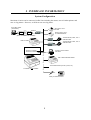
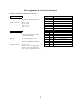
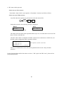
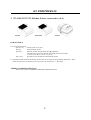
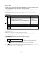
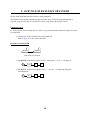
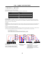
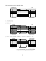
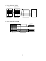
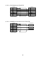
NX-5400
01 type
Interfaces and
Peripherals Manual
Sep.11.2002
CAUTION!
When the control key position is OFF, the display is off
and keyboard is disabled but the ECR's power is still
ON. So that before you open the upper case, make sure
that the AC cord is disconnected. Especially when you
replace the ROM, it must be disconnected, otherwise
the ECR will be damaged.
CONTENTS
I. INTERFACE INFORMATION ......................................................................................... 1
II. IRC SYSTEM ..................................................................................................................... 3
III. PERIPHERALS................................................................................................................. 5
1. TP-420/422/522/722 (Kitchen Printer, connected to ch-A) .................................................... 5
2. TP-620 (Slip Printer, connected to ch-A)................................................................................. 6
3. SCANNER .................................................................................................................................. 7
IV. PC COMMUNICATION ................................................................................................. 9
1. BATCH COMMUNICATION.................................................................................................. 9
2. PROGRAM LOADER (PLM 2000) ......................................................................................... 9
V. ECR TO ECR RAM DATA TRANSFER ...................................................................... 10
VI. JOURNAL DATA TRANSFER .................................................................................... 11
VII. CABLE CONNECTION............................................................................................... 12
1. CHANNEL A --- IRC LINE..................................................................................................... 12
2. CHANNEL B ............................................................................................................................ 13
1)
2)
3)
4)
5)
6)
ECR --- PC .................................................................................................................................. 13
ECR --- AUTO ANSWER MODEM (to AUTO DIAL MODEM --- PC) .................................. 13
ECR --- HANDY SCANNER ..................................................................................................... 14
ECR --- FLAT BED SCANNER................................................................................................. 14
ECR --- ECR FOR RAM DATA TRANSFER............................................................................ 15
ECR --- PERIPHERAL FOR JOURNAL DATA TRANSFER .................................................. 15
I. INTERFACE INFORMATION
System Configuration
Maximum 32 units can be connected via IRC line including the master, max. 4 kitchen printers and
max. 4 slip printers. However, an ECR can use one slip printer.
PC as IRC master
(Tensai2000)
Slip printer, max. 4
TP-620
RS232C
MODEM
MODEM
Kitchen printer, max. 4
TP-420/422/522/722
NA-720
(direct connection to PC available)
NA-710
ECR as master
Thermal kitchen printer, max. 1
CBM-233/1000
RS232C
Thermal kitchen printer, max. 3
CBM-233/1000
NA-730
RS232C
Standard Interface
PC batch communication
PLM 2000
Channel A : RS485
Channel B : RS232C
or
ECR to ECR RAM data transfer
or
Journal data transfer (monitor, printer, etc.)
2nd drawer is not available.
or
or
Handy or Flat-bed scanner
1
Pin Assignment & Character Structures
Channel A (RS485) and Channel B (RS232C)
CHANNEL A
(RS485, RJ-45 modular type connector)
Baud rate :
19,200 bps or 38,400 bps [SF-62.a]
Character structure :
PIN #
1
2
3
4
5
6
7
8
start bit = 1 bit
data bit = 8 bits
stop bit = 2 bits
parity = even
CHANNEL B
(RS232C, 9-pin D-sub female connector)
Block size :
256 or 512 characters for PC batch
communication [SF-66.e]
Baud rate :
300 ~ 38,400 bps [SF-66.f~h]
9,600 or 19200 bps [SF-62.d]
for ECR to ECR RAM data transfer
Character structure :
start bit = 1 bit
data bit = 7 bits or 8 bits [SF-66.b]
stop bit = 1 bit or 2 bits [SF-66.d]
parity = odd, even or null [SF-66.a,c]
PIN #
1
2
3
4
5
6
7
8
9
2
I/O
OUT
IN
OUT
IN
OUT
IN
OUT
SIGNAL
FUNCTION
DATA+ Comm. data signal (+)
DATAComm. data signal (-)
CTL+
Comm. line control (+)
CTL-
Comm. line control (-)
SIGNAL
P.GND
TXD
RXD
RTS
CTS
+5V
GND
DCD
DTR
FUNCTION
Protection ground
Transmitted data
Received data
Request to send
Clear to send
not used
Signal ground
Data carrier detect
Data terminal ready
II. IRC SYSTEM
The master PC or ECR can transmit programming data to the slave ECRs and collect the sales data
from the slave ECRs via channel A.
z
z
PC as Master using PC-IRC communication module Tensai2000
ECR as Master : Any ECR can be a master ECR.
Preparation
Before using the IRC system, the following presetting must be performed;
a) For new machines being added to the system, perform RAM test SP-9901 to erase all RAM
contents. Do not perform this operation on the machines already used as it will erase all
preset data.
b) Confirm the following three points on each ECR;
1. Each ECR is connected by the IRC line. Refer to VII. Cable Connection (page 12).
2. Confirm the machine number. (PGM-171)
The last two digits of the machine number used for ECR ID #, must be 31 out of '1 ~ 62' and
different for each ECR.
3. Confirm the baud rate is the same as the master by system function flag [SF-62.a]. (PGM-100)
SF-62
1/0
bit
a
1
Baud rate: IRC line (ch-A) is 38400 bps
3
0
19200 bps
c) IRC status check operation
In the case of a PC as master ;
Tensai2000: Status check is not required on Tensai2000. Perform it on ECR as follows.
In the case of an ECR as master ;
Any ECR where this operation is performed becomes the master ECR.
SP
8800
•
X
During this operation, the following message is displayed;
Master
Slave
##P-8800
-irc comm-nn
##: ECR sequential # (01~62)
nn: block #
The master ECR will check ECR sequential number up to 62, even when there are fewer ECRs
than 31 ECRs on the IRC line.
After IRC status check is completed, all ECR's connected can communicate via IRC line, and
the IRC system configuration table is printed as follows:
S-8800
01 #104 OK
02 #105 OK
03 #106 OK
#104-0006
ECR sequential #, machine #, IRC status
19:07P
If there is a communication error, 'NG' will be printed instead of 'OK'. Retry SP-8800
operation.
For the "Program data transfer from master to slaves", "IRC report" and "IRC error", please refer to
programming manual.
4
III. PERIPHERALS
1. TP-420/422/522/722 (Kitchen Printer, connected to ch-A)
TP-420
TP-522
TP-422/722
ECR SETTINGS
a) Program the following:
[SF-64.e~h]
kitchen printer to be used
[SF-65]
back-up kitchen printer
[SF-62.a]
baud rate for IRC line [1] 38400 bps, [0] 19200 bps
The character structure for IRC line has already been fixed on ECR.
(1 start bit, 8 data bits, 2 stop bits, even parity)
[PF-4.e~h]
PLU data to be transmitted to which kitchen printer
b) Program the ECR name and the kitchen printer name by the character programming (PGM-152). These
names are printed on the kitchen printer every time, like "ECR name --> KP name".
TERMINAL PRINTER SETTINGS
Refer to the respective TERMINAL PRINTER USER'S MANUAL.
5
2. TP-620 (Slip Printer, connected to ch-A)
form stopper release switch
Cancels the form stopper.
two-digit LED
RELEASE switch
Releases paper or starts / stops test printing.
PRINT switch
Feeds paper if buffer is empty or prints data which is in buffer.
FUNCTION switch
power switch
Back feeds paper.
ECR SETTINGS
a) Select following;
[SF-57.h]
[SF-62.a]
(PGM-179)
[1] with slip printer
baud rate for IRC line: [1] 38400 bps, [0] 19200 bps
The character structure for IRC line has already been fixed on ECR.
(1 start bit, 8 data bits, 2 stop bits, even parity)
Slip printer ID # (should match DIP SW 2 setting of TP-620)
b) See [SF-57 ~ 60] for other selections;
slip logo, slip print compulsory condition, automatic slip print, maximum item lines on slip, pre-feed
lines on slip, etc.
TP-620 SETTINGS
Refer to the separate document "TERMINAL PRINTER TP-620 USER'S MANUAL".
6
3. SCANNER
The handy scanner models HC66R (BHS-6060/R) and BCH5442-STA which are supplied by Uniwell
can be used immediately after the scanner cable is connected to channel B.
If they are supplied from third party or a scanner of other manufacturers, some settings are required.
Refer to the next page.
HC66R and BCH5442-STA’s factory settings: 9600 bps, 7-bit data, even parity, 1 stop bit
ECR SETTINGS
SF-62 1/0
SF-66
bit
1
b With scanner
c Expanded UPC-E code
d Source Marking Code :
8, 13-digit PLU codes including check digit are programmed
(ECR treats the last one digit as check digit.)
In-Store Marking Code (for non-embedded code [SF-76,78.e,f=00] ) :
10-digit article code with check digit is programmed as PLU code (also see
[SF-76,78.d])
a
b
c
d
e
f
g
h
Character structure: Odd parity
Character structure: 8-bit data
Character structure: Parity permitted
Character structure: 2 stop bits
Block size is 512 characters
Baud Rate [f,g,h]
[000] 38400 bps; [001] 19200 bps;
[100] 2400 bps;
[101] 1200 bps;
0
without scanner
normal UPC-E code
does not include check digit
(7, 12-digit PLU code are
programmed)
10-digit article code only
(also see [SF-76,78.d])
Even parity
7-bit data
prohibited
1 stop bit
256 characters
[010] 9600 bps;
[110] 600 bps;
[011] 4800 bps;
[111] 300 bps
SCANNER SETTING
Set the followings by a preset bar code menu or a dip switch of the scanner;
- Communication condition (baud rate, data length, stop bit, parity) to match ECR's setting.
- RTS/CTS handshake (fixed)
- Message RTS/CTS (fixed) --- not character RTS/CTS
[INFORMATION] If the scanner's data format is as below it can be used.
trailer
data: 00H~0FH, normally CR (0DH) is used
data (numeric: 30H~39H)
code mark (any data can be used except 30H~39H, no data is also available)
header (any data can be used except 30H~39H, normally STX 02H is used)
Note: Depending on scanner, the timing which deactivates RTS is fast. In this case, please set scanner to send 2byte trailer data (post-amble). For example, CR & LF.
7
Settings for scanner from third party
When you are using BHS-6060 and BCH-5442-STA supplied from third party or a scanner of other
manufacturers, some settings are required. Perform the following steps:
1. Connect the scanner to the correct ECR's interface port. RTS signal need to be wired.
2. Set the system function flags of ECR.
3. Set the followings on the scanner by a preset bar code menu or a dip switch of the scanner.
a. Message (not text) RTS/CTS handshake must be set. Some scanner has this fixed.
b. If there is a selection either "scanner ready" or "data ready", choose "data ready".
c. "Baud rate, data length, stop bit, parity" should be matched to the ECR's settings.
d. Set the data transmission format of the scanner. Refer to the previous page.
4. Check the scanner works with ECR.
5. If the scanner does not work, the timing of the scanner which deactivates RTS may be fast.
In order to delay the deactivating timing, increase the trailer (post-amble, terminator) to 2 byte data
from 1 byte data. Set "CR, LF" for example. Then the scanner will work with ECR.
8
IV. PC COMMUNICATION
The following functions can be done with a PC through one of channel B.
1. BATCH COMMUNICATION
Set terminal address (PGM-172) to communicate with ECR. Refer to the programming manual for
the sequence. For details about PC batch communication, refer to PROTOCOL MANUAL UCP-101
and a separate appendix.
REMOTE MEMORY CHANGE
By remote memory change, the PC can modify the memory contents of the ECR. This function
consists of the following three types;
a) Memory Change
Alters the ECR's memory contents, by designating the memory address.
b) Memory Management
Alters the contents of the PLU, group and cashier memories.
c) Date/Time Change
Sets the date and time from the PC.
REMOTE MEMORY DUMP
By remote memory dump, the PC can read the memory contents of the ECR.
a) X/Z Report Dump
The X/Z report dump is similar to the X/Z report of the ECR. Using this function, the PC can collect or reset
an individual ECR's data.
b) Complete Memory Dump
Collects the ECR's complete memory data from the PC. This is used mainly for making a back-up file of the
ECR memory on the PC.
2. PROGRAM LOADER (PLM 2000)
Using the software PLM 2000, the ECR's data can be uploaded/edited on the PC and restored to the
ECR. Please follow the steps on the PLM 2000 to setup.
9
V. ECR TO ECR RAM DATA TRANSFER
ECR to ECR RAM data transfer is done by using channel B.
This transfer will send the programming data and sales data. If only the programming data is
required, reset the sales data by issuing all Z-reports, then follow the sequence below.
PREPARATION
1) Set the system function flags [SF-62.e, SF-66.a~d] (communication condition settings for ch-B)
for both ECRs.
2) Connect the ECR to another ECR using channel B.
Refer to page 15 for the cable connection.
RAM DATA TRANSFER
A
B
From ECR A to ECR B
1) On ECR B, perform the sequence below. Check that "-- Pc-in --" is displayed.
SP
1002
X
•
2) On ECR A, perform the sequence below. "-- Pc-out --" is displayed during the
communication.
SP
1001
X
•
10
VI. JOURNAL DATA TRANSFER
The journal data is transmitted to a peripheral device through channel B. For the cable connection,
refer to the next section.
PREPARATION
Set the following flags on ECR and the peripheral device to match ECR's communication condition below:
1/0
SF-62
SF-66
bit
1
h Journal data transmitted through channel B
a
b
c
d
e
f
g
h
Character structure:
Character structure:
Character structure:
Character structure:
0
not transmitted
Odd parity
8-bit data
Parity permitted
2 stop bits
Baud Rate [f,g,h]:
[000] 38400 bps;
[100] 2400 bps;
Even parity
7-bit data
prohibited
1 stop bit
[001] 19200 bps;
[101] 1200 bps;
DATA FORMAT
[010] 9600 bps;
[110] 600 bps;
journal data
[011] 4800 bps;
[111] 300 bps
C L
R F
(24 digits)
TRANSMITTED CHARACTER
CODE
0
1
2
3
4
5
6
7
8
9
A
B
C
D
E
F
0
LF
CR
1
2
3
4
5
6
7
Space
0
1
2
3
4
5
6
7
8
9
:
φ
<
Σ
>
?
@
A
B
C
D
E
F
G
H
I
J
K
L
M
N
O
P
Q
R
S
T
U
V
W
X
Y
Z
Ä
Ö
Ü
Æ
Space
a
b
c
d
e
f
g
h
i
j
k
l
m
n
o
p
q
r
s
t
u
v
w
x
y
z
#
$
%
&
'
£
Ñ
*
Å
.
/
8
9
◊
ä
§
β
=
↑
DW
_
(
)
Double-width characters (7F) are converted to one character code and one space code.
11
VII. CABLE CONNECTION
1. CHANNEL A --- IRC LINE
RJ-45 Modular Type Cable Information
Please use the straight LAN cable (shielded type) which is generally sold.
RS422/485 Shielded Twisted Pair
Conductor:
AGW24
Characteristic impedance:
< 100 ohms
Capacitance per meter:
40 - 100 pF
Attenuation at 1Mhz / 100m:
2 - 6 db
Cable length:
max. 1200 m
Connectors and Connector Shells:
Ideally use: EMI / RFI Shielding RJ45 type
About Ground
Each ECR must be grounded at the same level and the termination resistors must be fitted on the first and last
devices on the line. Please refer to the document "IRC & TERMINAL PRINTER CABLING INSTRUCTION
(RS-485)" for how to connect cables.
Joint Box
JOINT BOX 485 (REF.# 62092) makes the cable connection simple, quick, and easy between Uniwell ECRs and
Terminal Printers on an IRC line (RS-485). Refer to the option instruction manual for details and connection
samples.
Ferrite Core when TP-722 is connected:
A ferrite core must be also purchased from third party and fasten beside the IRC cable connector of ECR and TP722 (9-pin D-sub or modular) to prevent radio interference. Any type of ferrite core can be used.
Recommended ferrite core size
Approx. Height 21 mm x Length 21 mm (Inside Diameter: 6.5 mm)
For the inside diameter, please measure the cable used by yourself.
1K
1
2
3
DATA+ DATA- CTL+
220
6
CTL-
ECR channel A
RJ45 modular type connector with shield
1K
1
2
3
6
RJ45 with shiled
To ECR (ch-A)
To kitchen/receipt printer
TP-722 (RJ45)
1K ohm termination resistor (1Kohm)
220 ohms termination resistor (220ohms)
12
1
2
3
4
5
1
2
220
3
4
1 P.GND 2 DATA+ 3 DATA- 4 CTL+ 5 CTL9-way male D-sub connector
To slip printer TP-620
To kitchen/receipt printer TP-420/422/522
TP-722 (D-sub)
To Network Adapter NA-720 (MASTER)
To Network Adapter NA-710/730 for kitchen
printer CBM-233/1000
5
Cable connection between NA-720 (CH1) and PC
To PC
To NA-720 CH 1
(RS232C)
1
P.GND
2
TXD
3
RXD
4
RTS
5
CTS
6
+5V
7
GND
8
DCD
9
DTR
9-way male
D-sub connector
* Connect ground to D-sub shell
2
3
1
4
RXD
TXD
DCD
DTR
5
GND
7
RTS
8
CTS
9-way female
D-sub connector
2. CHANNEL B
1) ECR --- PC
To ECR
1
P.GND
2
TXD
3
RXD
4
RTS
5
CTS
6
+5V
7
GND
8
DCD
9
DTR
9-way male
D-sub connector
To PC
2
3
1
4
RXD
TXD
DCD
DTR
5
GND
7
RTS
8
CTS
9-way female
D-sub connector
2) ECR --- AUTO ANSWER MODEM (to AUTO DIAL MODEM --- PC)
To Auto Answer
Modem (DCE)
2
TXD
3
RXD
4
RTS *1
5
CTS
To ECR
1
P.GND
2
TXD
3
RXD
4
RTS
5
CTS
6
+5V
7
GND
8
DCD
9
DTR
9-way male
D-sub connector
7
8
GND
DCD *2
9 or 25-way female
D-sub connector
*1 Do not connect when ECU (Error Correction Unit) is fitted.
*2 May be omitted when using duplex (LINNET) Modem.
13
3) ECR --- HANDY SCANNER
ECR
1
2
3
4
5
6
7
8
9
P.GND
TXD
RXD
RTS
CTS
+5V *
GND
DCD
DTR
9-way female
D-sub connector
*max. 200 mA
Handy Scanner
Connector
P.GND
1
2
TXD
3
4
5
+5V
6
GND
7
RTS
8
CTS
9
HANDY
SCANNER
9-way male
D-sub connector
4) ECR --- FLAT BED SCANNER
To Flat Bed
Scanner
To ECR
1
P.GND
2
TXD
3
RXD
4
RTS
5
CTS
6
+5V
7
GND
8
DCD
9
DTR
9-way male
D-sub connector
TXD
GND
RTS
CTS
14
5) ECR --- ECR FOR RAM DATA TRANSFER
To ECR
1
P.GND
2
TXD
3
RXD
4
RTS
5
CTS
6
+5V
7
GND
8
DCD
9
DTR
9-way male
D-sub connector
To ECR
1
P.GND
3
RXD
2
TXD
8
DCD
9
DTR
6
+5V
7
GND
4
RTS
5
CTS
9-way male
D-sub connector
6) ECR --- PERIPHERAL FOR JOURNAL DATA TRANSFER
To Peripheral
To ECR
1
P.GND
2
TXD
3
RXD
4
RTS
5
CTS
6
+5V
7
GND
8
DCD
9
DTR
9-way male
D-sub connector
RXD
RTS or DTR
GND
15