1
Chapter 3
Installation
3.5 Serial Port
3.5.1 RS232 Serial Port
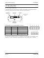
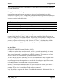
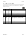
The serial port is a 9 pin DB9 female and provides for connection to a terminal or to a PC for
configuration, field testing and for factory testing. It is also used by the Modbus/DF1 version
for fieldbus connection.
This port is internally shared with the RS485 - ensure that the RS485 is disconnected before
attempting to use the RS232 port. Communication is via standard RS232 signals. The 105G
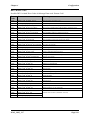
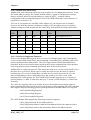
is configured as DCE equipment with the pinout detailed below.
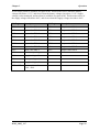
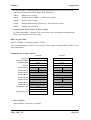
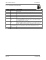
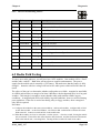
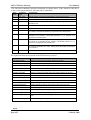
DB9 Connector Pinout:
Pin
Name
Direction
1
DCD
Out
Function
Used for "active" signal.
2
RD
Out
Serial Data Output
3
TD
In
4
DTR
In
Serial Data Input
Data Terminal Ready - may be used by Host Protocol
Driver
5
SG
6
DSR
Out
Data Set Ready - always high when unit is powered on.
7
RTS
In
Request to Send - may be used by Host Protocol Driver
8
CTS
Out
Clear to send - may be used by Host Protocol Driver
9
RI
Signal Ground
Ring indicate - not connected
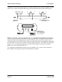
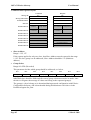
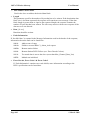
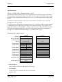
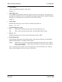
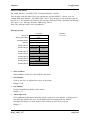
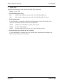
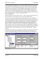
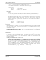
Hardware handshaking using the CTS/RTS lines is provided, and are under the control of the
Host Comms Driver. Example cable drawings for connection to a DTE host (a PC) or another
DCE host are detailed below:
105U-G
DB9
105U-G
DB9
3.5.2 RS485 Serial Port
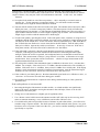
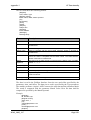
RS485 should not be used with the DF1 unit. The RS485 port provides for communication
between the 105G unit and its host device using a multi-drop cable. Up to 32 devices may be
MAN_105G_1.17
Page 34