1
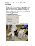
JEOL JEM 2010 TRAINING TRANSMISSION ELECTRON
MICROSCOPE
USER MANUAL
Version 5.1
EM Facility CMSE-SEF
Massachusetts Institution of Technology
March 2009
TABLE OF CONTENTS
1. Specifications.................................................................................................................2
1.1
1.2
1.3
1.4
Performance.............................................................................................................2
Electron optics system.............................................................................................2
Specimen stage........................................................................................................2
Vacuum System.......................................................................................................2
2. Description of Column and Panel Controls............................................................. ......3
2.1 Column.....................................................................................................................3
2.1.1 Condenser aperture assembly......................................................................4
2.1.2 Condenser mini-lens shifting screws...........................................................5
2.1.3 Specimen holder..........................................................................................5
2.1.4 Goniometer..................................................................................................5
2.1.5 Objective lens aperture assembly................................................................6
2.1.6 SAD aperture assembly (Field limiting aperture assembly) .......................6
2.1.7 Intermediate lens shifting screws.................................................................7
2.1.8 Projector lens shifting screws......................................................................7
2.1.9 Screen level..................................................................................................7
2.1.10 Camera chamber door handle......................................................................7
2.1.11 Pedal switches..............................................................................................7
2.2 Control Panels..........................................................................................................8
2.2.1 Control Panel L1..........................................................................................9
2.2.2 Control panel R1........................................................................................11
2.2.3 Control Panel L2........................................................................................13
2.2.4 Control panel R2........................................................................................15
2.2.5 Control Panel L3........................................................................................17
2.2.6 Control panel SC........................................................................................18
2.2.7 Control Panel GC.......................................................................................18
2.2.8 Control panel KB and CRT........................................................................19
3. Basic Operation.............................................................................................................20
APPENDIX I
APPENDIX II
APPENDIX III
APPENDIX IV
APPENDIX V
APPENDIX VI
Camera Length Calibration.....................................................................26
EDS/NBD/CBD Alignment...................................................................26
High-Resolution Imaging......................................................................27
Removing and Inserting the Sample Holder.........................................28
JEOL 2010 Operation Summary...........................................................30
JEOL 2010 STEM Alignment...............................................................32
EM FACILITY CMSE-SEF
1
March 2009
1 Specifications
1.1 Performance
Guaranteed resolution: 1.4 Å (lattice) and 1.94 Å (point to point)
Accelerating voltage: 80, 100, 120, 160, 200 kV
Magnification (at 200kV):
Standard magnification mode: 2,000× to 1,500,000×
Selected area magnification mode: 2,000× to 1,500,000×
Low magnification mode (LOW MAG): 50× to 1,000×
Electron diffraction camera length:
Selected area electron diffraction: 8 to 200 cm
1.2 Electron optics system
Illumination system includes the electron gun and condenser lens.
The electron gun (multi-stage beam stage) is a standard self-biasing LaB6 filament.
The condenser lens system is four stage condenser lens: 1st, 2nd, 3rd, and mini-lens.
The condenser aperture sizes are 10, 20, 50, 70, and 120 µm in diameter.
Imaging forming system includes an objective lens, 1st and 2nd intermediate lens and a
projective lens. The ultra-high resolution (UHR) pole piece is used in the objective lens.
The objective aperture sizes are 20, 40, 60 and 120 µm in diameter. SAD aperture sizes
are 10, 20, 50 and 100 µm in diameter. In Low-Mag mode, the objective lens is turned
off and the objective mini-lens is active.
1.3 Specimen stage
Specimen holder is exchanged with airlock mechanism with two stage evacuation. X, Y,
Z and X tilt are all motor-driven. The movement range of X and Y directions is ± 1 mm.
The specimen tilt angle is ±15º for both X tilt and Y tilt.
1.4 Vacuum system
It includes an oil rotary pump, an oil diffusion pump, and a sputter ion pump (SIP). The
diffusion pump is for pumping of the specimen chamber and the camera chamber, and the
SIP is for the pumping of the column and gun chamber.
EM FACILITY CMSE-SEF
2
March 2009
2 Description of Column and Panel Controls
2.1 Column
The essential column parts are shown in Fig. 2.1 and 2.2.
Fig. 2.1 External view of column
EM FACILITY CMSE-SEF
3
March 2009
Fig. 2.2 Cross-section of microscope column
2.1.1
Condenser aperture assembly (Fig. 2.3)
Knob 1 and level: The apertures are selected corresponding to the knob 1
position and level direction.
EM FACILITY CMSE-SEF
4
March 2009
Knob 2, 3, 4: Knobs 2 and 3 used for precisely aligning the aperture in the
electron beam path by shifting the aperture in the X and Y directions on the
horizontal plane when the level is turned to the left. Knobs 2 and 4 are used when
the level is turned to the right. The apertures sizes are:
Lever Position to Left: 120 µm, 70 µm, 50 µm
Lever Position to Right: 20 µm, 10 µm, Open
Fig. 2.3 Condenser aperture assembly
2.1.2
Condenser mini-lens shifting screws
Used for illumination system alignment.
2.1.3
Specimen holder
Bring a specimen into/from the electron beam path.
2.1.4
Goniometer (Fig. 2.4)
Fig. 2.4 Goniometer
EM FACILITY CMSE-SEF
5
March 2009
A specimen holder is inserted and tilted with a motor in the goniometer.
TX knob: Defines the specimen X-tilt range.
TY knob: Defines the specimen Y-tilt range.
Z knob: Defines the specimen shifting range in the specimen vertically.
Green lamp: When lit, indicates that the specimen holder insertion and
removing is ready.
Red lamp: When lit, indicates that the goniometer is being roughly evacuated.
PUMP/AIR switch: Setting this switch to PUMP evacuates the goniometer (the
red lamp lights up during evacuation) and the goniometer vacuum is broken
when this switch is set to AIR. Switch setting can not be performed unless the
switch is pulled.
Connector: For optional specimen holders such as a double-tilt specimen
holder.
2.1.5
Objective lens aperture assembly (Fig. 2.5)
Knob 1 and 3: Used for precisely aligning the aperture in the electron beam path
by shifting the aperture in the X and Y directions on the horizontal plane.
Knob 2: Used for selecting the objective lens apertures. By turning the knob
clockwise, the 120→60→40→20 µm diameter apertures are respectively
positioned in the electron beam path. As the aperture size is reduced, the
electron beam intensity is also reduced. The aperture is removed from the beam
path by positioning the knob at red spot.
Fig. 2.5 Objective lens aperture assembly
2.1.6
SAD aperture assembly (Field limiting aperture assembly) (Fig. 2.6)
Knob 1: Used for selecting the SAD apertures. By turning the knob clockwise,
the 100→50→20→10 µm diameter apertures are respectively positioned in the
electron beam path. As the aperture size is reduced, the electron beam intensity
is also reduced. The aperture is removed from the beam path by positioning the
knob at red spot.
Knob 2 and 3: Used for precisely aligning the aperture in the electron beam path
by shifting the aperture in the X and Y directions on the horizontal plane.
EM FACILITY CMSE-SEF
6
March 2009
Fig. 2.6 SAD aperture assembly
2.1.7
Intermediate lens shifting screws (SERVICE ONLY)
Used for shifting the intermediate lens in conjunction with the intermediate lens
shifting knobs, in order to align the image forming system.
2.1.8 Projector lens shifting screws (SERVICE ONLY)
Used for shifting the projector lens in order to align the image forming system.
2.1.9
Screen level
Used when observing the image through binoculars. By pulling the level towards
users, the small fluorescent screen is inclined 45º.
2.1.10 Camera chamber door handle
Used for opening and closing the camera chamber door (You have to turn
Nitrogen gas on). By turning the handle clock-wise as far as it will go (9 clock
position), the electron gun filament power is switch off, the AIRLOCK OPEN
lamp goes out, the airlock valve V2 close, air is admitted into the camera chamber
door open. By turning the handle counter-clockwise as far as it will go (6 clock
position, i.e., the original position) with the door closed, the two chambers are
evacuated, upon completion of evacuation (when the vacuum reaches the required
value), the airlock valve automatically opens and the CAMERA: AIRLOCK
OPEN lamp lights up.
2.1.11 Pedal switches
X pedal switches (left): By stepping on one of the pedals, the specimen is titled
around the X-axis in one direction and by stepping on another pedal, the specimen
is tilted around the X-axis in the opposite direction.
Y pedal switches (right): When a rotation specimen holder is used, the specimen
is rotated in one direction by stepping on one of the pedals and rotated in the
opposite direction by stepping on the other pedal. When a double-tilt specimen
holder is used, the specimen is tilted around the Y-axis in one direction by
EM FACILITY CMSE-SEF
March 2009
7
stepping on one pedal and tilted around the Y-axis in the opposite direction by
stepping on the other pedal. Further, when a specimen elongating holder is used,
the specimen is elongated by stepping on one pedal and compressed by stepping
on the other pedal.
2.2
Control Panels
The control panels are conveniently located for operational ease (as shown in Fig.
2.7).
Fig. 2.7 Location of control panels
EM FACILITY CMSE-SEF
8
March 2009
2.2.1
Control Panel L1 (Fig. 2.8)
Fig. 2.8 Control panel L1
(1) EMERGENCY STOP button: Used for shut off the instrument in an
emergency.
(2) POWER (key) switch: Used for starting-up and shutting down the
instrument.
(3) ACCEL VOLTAGE READY lamp: Indicates that the instrument is ready
for high voltage generation. That is, this lamp (green when lit) indicates that
the anode chamber pressure has dropped to a certain specified value or less
and that the pressure of the isolation gas in the gas chamber has increased to
a certain value or more. This lamp flickers while the accelerating voltage is
increasing.
(4) ACCELERATING VOLTAGE switch: Setting this switch upwards (or
downwards) increases (or decrease) the accelerating voltage value displaced
on the CRT (R1-14). If the HT (L1-5) is not lit, no voltage is generate
although an accelerating voltage value is displayed on the CRT.
(5) HT switch: The lamp lights up, when depressed, and an accelerating voltage
selected with the ACCEL VOLTAGE (L1-4) is generated if the ACCEL
VOLTAGE READY (L1-3) is lit. Redepressing this switch turns off the
accelerating voltage.
(6) Beam CURRENT meter: Indicates the sum of the beam current and
detecting current in the high voltage power supply.
(7) FILAMENT READY: Indicates, when lit, that the electron gun filament
can be ignited.
(8) FILAMENT knob: Turning this knob clockwise increases the current
applied to the gun filament if the FILAMENT READY (L1-7) is lit.
(9) PANEL LIGHT knob: Controls panel illumination brightness.
EM FACILITY CMSE-SEF
March 2009
9
(10) BIAS: Controls the electron gun bias.
Indicator: Indicates the bias value.
Switch: Turning this switch upwards increases the bias value and the beam
current indicated on the BEAM CURRENT (L1-6).
(11) ROOM LAMP switch: For turning on and off a room lamp.
(12) SPOT SIZE switch: Setting this switch to the left position increases the
spot size (the size of the electron beam which has been maximally converged
with the BRIGHTNESS). The spot size value is displayed on the CRT (R114).
(13) DEFLECTOR switches: When one of these switch is depressed, the
depressed switch lamp brightness and the coil current relating to the
depressed switch becomes variable with the left and right SHIFT or DEF
knobs (L1-17, R-1 or L1-18, R1-2). The lamp darkens and the coil current
remains fixed at the present value when the switch is redepressed.
COND STIG: When depressed, condenser lens stigmator coil current can be
varied.
OBJ STIG: when depressed, the current stored in the memory, which is
designated by the cam switch located under this button switch, is applied to
the objective lens stigmator coil (to the intermediate lens stigmator coil in the
case of the LOW MAG mode) and becomes variable.
DARK TILT: When this is depressed, the current stored in the memory,
which is designated by the cam switch located under this button switch, is
applied to the condenser lens beam coil and becomes variable. The lamp
above this switch indicates, when lit, that this switch has been turned on, and
remains lit until the adjacent BRIT TILT is depressed. The DARK TILT is
used to tilt the electron beam when observing mainly a dark field image.
BRIT TILT: Same as the DARK TILT. Used to align the optical axis by
tilting the electron beam. The lamp above this switch lamp remains lit until
the DARK TILT is depressed. The BRIT TILT is used to tilt the electron
beam when observing mainly a bright field Image.
IMAGE SHIFT: For image shifting at high magnifications.
(14) BRIGHTNESS knob: Converges and spreads the electron beam. Varies
the 3rd condenser lens current. An alarm sounds when the current exceeds
the specified value.
counterclockwise and clockwise from the midway position, respectively. At
the midway, both lamps light up.
(15) SHIFT-CRS switch: When depressed, the current rate per notch of the
BRIGHTNESS, SHIFT X and SHIFT Y knobs (L1-14, 17, R1-1) is enlarged
16 times.
(16) DEF-CRS switch: When depressed, the current rate per notch of the DEF X
and DEF Y knobs (L1-18, R1-2) is enlarged 16 times.
(17) SHIFT-X knob: Used for shifting the electron beam in the X direction by
varying the condenser lens beam deflector coil current. The two lamps above
this knob light up when this knob is set to the midway position. When this
knob is turned clockwise (or counterclockwise) from its midway position, the
EM FACILITY CMSE-SEF
March 2009
10
left (or right) lamp goes out. An alarm sounds indicating that the knob has
been turned beyond the specified variable range.
(18) DEF-X knob: Varies the X current in the coil selected with the
DEFLECTOR (l1-13). The two lamps above this knob function in the same
manner as those above the SHIFT X (L1-17). The two lamps, however, are
unlit when no coil is connected to this knob.
(19) TEM switch: When depressed, the built-in lamp brightens and the
illumination mode is set to the TEM mode (wide area illumination mode).
(20) EDS switch: When depressed, the built-in lamp brightens and the
illumination mode is set to the EDS mode (high current density micro-area
illumination mode).
(21) NBD switch: When depressed, the built-in lamp brightens and the
illumination mode is set to the NBD mode (small convergence angle microarea illumination mode).
(22) CBD switch: When depressed, the built-in lamp brightens and the
illumination mode is set to the CBD mode (wide range changeable
convergence angle micro-area illumination mode).
(23) α-SELECTOR knob: Select the convergence angle with the illuminating
area kept unchanged in size. The Cm lens current decreases and illuminating
angle becomes larger as ths is turned clockwise. The CM lens current
decreases to zero when this is turned fully clockwise.
2.2.2
Control panel R1 (Fig. 2.9)
Fig. 2.9 Control panel R1
(1) SHIFT-Y knob: Used for shifting the electron beam in the Y direction by
varying the condenser lens beam deflector coil current. The two lamps above
this knob light up when this knob is set to the midway position. When this
knob is turned clockwise (or counterclockwise) from its midway position, the
left (or right) lamp goes out. An alarm sounds indicating that the knob has
been turned beyond the specified variable range.
EM FACILITY CMSE-SEF
11
March 2009
(2) DEF-Y knob: Varies the Y current in the coil selected with the
DEFLECTOR (control panel L1). The two lamps above this knob function
in the same manner as those above the SHIFT Y (R1-1). The two lamps,
however, are unlit when no coil is connected to this knob.
(3) FUNCTION: Used for selecting an image forming mode. The
magnification or camera length in the selected mode can be varied with the
SELECTOR switch (control panel R1), and is displayed on the CRT (PAGE1) on control panel R1. The magnification or camera length set by the
SELECTOR switch is stored so that even if another mode is once selected,
the magnification or camera length can be set to the stored value by selecting
the original mode again.
MAG1 switch: Used for selecting the normal magnification mode.
MAG2 switch: By depressing this switch, a specific magnification is
obtained. In this mode, the magnification can be increased or decreased from
the specific magnification with the SELECTOR switch. The magnification
set in this mode is not stored.
LOW MAG switch: Used for selecting the low magnification mode.
SAM/ROCK switch: Used for selecting the selected area magnification
mode (or the rocking mode when the EM—ASID scanning device is used).
DIFF switch: Used for selecting the diffraction mode. In this mode, the
camera lengths for selected area diffraction, those for high dispersion
diffraction, and that for high resolution diffraction can be selected in the
camera length ascending order with the SELECTOR switch. The selected
camera length is displayed on the CRT (PAGE—1) on control panel R1.
(4) OBJ FOCUS: Used for focusing the image by varying the objective lens
current (OM lens in case of LOW MAG mode).
Knobs: The amount of current variation when the large knob is turned
one notch is the same as when the small knob is turned 16 notches.
Switch: Setting this switch to 1, 2, 3 or 4 enlarges the amount of current
variation per notch by 1, 16, 256 or 4,096 times, respectively.
(5) WOBBLER: Used for generating alternating current or imposing a small
cyclic electrical variation on the related current or voltage.
IMAGE X and Y switches: Used for focusing. The 1st and 2nd beam
deflector coil currents vary periodically when one of these switches is turned
on. If the image is out of focus, it wobbles in the X direction when the
IMAGE X switch is turned on and in the Y direction when the IMAGE Y switch
is turned on.
HT switch: By depressing on this switch, the high voltage is periodically
varied, facilitating the voltage center alignment.
(6) DIFF FOCUS knob: Used for varying the 1st intermediate lens coil current
for focusing the field limiting aperture image when the FUNC TION—
SAM/ROC switch (control panel R1) is depressed, and for focusing the
diffraction pattern when the FUNCTION—DIFF switch is depressed.
(7) SELECTOR switch: Used for varying the normal magnification when the
FUNCTION—MAG 1 or — MAG 2 switch (control panel R1) is depressed,
the low magnification when the FUNCTION — LOW MAG switch is
EM FACILITY CMSE-SEF
March 2009
12
depressed, the selected area magnification (or the rocking angle in case the
EM—ASID is used) when the FUNCTION—SAM/ROCK switch is
depressed, and the camera length when the FUNCTION—DIFF switch is
depressed. Setting this switch to the left position decreases the value and
setting the switch to the right position increases the value. The magnification
or camera length set by this switch is displayed on the CRT (PAGE—1) on
control panel R1.
(8) PHOTO switch: By depressing this button when the lamp is unlit, a film is
advanced to the exposure position, the lamp lights up when the film reaches
the said position, the film is exposed and advanced, and the lamp goes out.
By depressing this button when the lamp is lit, that is, when a film is in the
exposure position, the film is exposed.
(9) EXP lamp: Indicates, when lit, that the shutter is open.
(10) SCREEN switch: Used for changing the large fluorescent screen position
(horizontal or vertical). The built-in lamp lights up and remains lit while the
screen is at the vertical position.
(11) FILM ADVANCE AUTO switch: When this switch is turned on, the builtin lamp lights up and switch unused films are successively advanced to the
exposing position without depressing the PHOTO switch (control panel R1).
When the switch is turned off, the lamp goes out and no film is advanced to
the exposing position unless the PHOTO switch is depressed.
(12) SHUTTER AUTO switch: When this switch is turned on, the built-in lamp
lights up and the shutter is automatically controlled. When the switch is
turned off the lamp goes out and the shutter is controlled manually.
(13) EXP TIME switch: Used for setting the exposure time in the manual
exposure mode. Setting this switch to the lower position decreases the
exposure time, and setting the switch to the upper position increases the
exposure time. The exposure time set by this switch is displayed on the CRT
(PAGE—1) on control panel R1.
(14) CRT: Used for displaying information as requested.
(15) CONT knob: Adjusts the CRT contrast.
(16) BRIGHT knob: Adjust the CRT brightness.
(17) H HOLD controller: Synchronizes the CRT image horizontally.
(18) TV IMAGE switch: For optional attachments.
(19) V HOLD controller: Synchronizes the CRT image vertically.
2.2.3
Control panel L2 (Fig. 2.10)
EM FACILITY CMSE-SEF
13
March 2009
Fig. 2.10 Control panel L2
(1) BAKE OUT timer: Setting the column baking time.
(2) UNA switch: Setting the microscope evacuation system to the day-and-night
evacuation mode. The ion pump will remain turned on when the EM is turned off
with this switch turned on.
(3) Potentiometers: Adjust the vacuum gauge circuit voltages and currents. For
maintenance and troubleshooting.
(4) SIP switch: Must be turned on before turning on the BAKEOUT switch to bake
out the ion pump.
(5) BAKEOUT switch: To bake out the ion pump (with the SIP switch turned on)
and the microscope column.
(6) ACD HEAT switch: For the anticontamination device heater power.
(7) GUN LIFT switch: Power on/off switch for the lift. By turning this switch ON
after breaking the electron gun chamber vacuum using the GUN AIR switch
(control panel L2), the electron gun is raised.
(8) Vacuum gauge selector: Selects the Pirani vacuum gauge PI1 (COLUMN), PI2
(GUN), PI3 (CAMERA), P14 (specimen chamber), PI5 (RT) or Penning vacuum gauge
PEG (see the evacuation system diagram on control panel L2). Gauge readings are
shown on the meter (control panel L2).
(9) GUN AIR switch: The built-in lamp lights up when this switch is turned on and
air is admitted into the electron gun chamber.
(10) COL AIR switch: The built-in lamp lights up and air is admitted into the
column (except the viewing and electron gun chambers) when this switch is
turned on.
(11) Meter: Indicates the pressure measured with the vacuum gauge selected with
the vacuum gauge selector. The Pa or µA scale is used when the selector is set at
PEG or other. 20 µA indicate high vacuum and 250 µA indicates the atmospheric
pressure. When lamp H on the right-hand side of this meter is lit, read the upper
(outer) scale, and when lamp L is lit, read the lower (inner) scale when the
vacuum gauge selector is set at PEG.
(12) RESET switch: Used to reset the alarm circuit when alarm lamp(s) light(s) up.
(13) ALARM lamps:
EM FACILITY CMSE-SEF
14
March 2009
AIR: AIR Lights to indicate that the compressed air pressure is lower than the
specified value.
RP: Lights to indicate that the rotary pump belt is broken.
DP: Lights to indicate that the oil diffusion pump heater is broken.
WATER: Lights to indicate that the cooling water flow rate of the oil diffusion
pump is smaller than the specified value.
PIG: Lights to indicate that Pirani gauge(s) is (are) broken.
RT: Lights to indicate that the pressure in the vacuum reservoir has decreased to
the specified value.
(14) Evacuation system diagram: Shows the state of the microscope evacuation
system. The valve lamp(s) light(s) up when the corresponding valve(s) open(s).
Valve lamp 17 lights up, however, when the valve closes. PI1, PI2, ... indicate
Pirani gauges and PE indicates Penning gauge. SIP, RP and DP indicate ion
pump, oil rotary pump and oil diffusion pump, respectively.
2.2.4
Control panel R2 (Fig. 2.11)
Fig. 2.11 Control panel R2
(1) DEFLECTOR: When one of these switches is turned on (or depressed), the
built-in lamp lights up and the current in the deflector coil related to the
depressed switch can be varied by the SHIFT and DEF (R2—7, 13).
GUN: The electron gun beam deflector coil current can be varied with the
SHIFT and DEF.
EM FACILITY CMSE-SEF
15
March 2009
SPOT: The spot alignment coil current can be varied with the SHIFT.
COND: The condenser lens beam deflector coil current can be varied with
the SHIFT and DEF.
IMAGE: The image shift coil current can be varied with the SHIFT and
DEF.
PROJ: The projector lens beam deflector coil current can be varied with the
SHIFT.
(2) STIGMATOR switches: By depressing one of the switches, the stigmator
coil related to the depressed switch is connected to the DEF (R2—13).
COND: For the condenser lens astigmatism correction.
OBJ: For the objective lens astigmatism correction.
INT: For the intermediate lens astigmatism correction.
(3) COND DEF ADJ switches: These switches adjust the condenser lens beam
deflector coil.
SHIFT: The lamp lights up, when depressed, and the ratio of the currents in
the condenser lens beam deflector can be varied with the SHIFT and DEF
(R2—7, 13). This is used to adjust the deflector so that the electron beam
does not tilt even if the electron beam is shifted with the left and right SHIFT
knobs (L1—17, R1—1).
TILT: The lamp lights up, when depressed, and the ratio of the currents in
the condenser lens beam deflector can be varied with the SHIFT and DEF
(R2—7, 13). This is used to adjust the deflector so that the electron beam
does not tilt even if the electron beam is tilted with the left and right DEF
knobs (L1—18, L1—2). Also used for IMAGE X and IMAGE Y (R1—5)
adjustment..
(4) WOBBLER switches:
GUN switch: The built-in lamp lights up and the electron gun first beam
deflector current pulsates when this switch is turned on. Used for column
alignment.
COND switch: The built-in lamp lights up and the 3rd condenser lens
current pulsates when this switch is turned on. Used for condenser aperture
centering.
OBJ switch: The built-in lamp lights up and the objective lens current
pulsate when this switch is turned on. Used for current center alignment.
(5) N switch: The built-in lamp light up, when depressed, and the current in the
coil selected with the DEFLECTOR, STIGMATOR or COND DEF ADJ
(R2—1, 5 or 6) is set to the specified value.
(6) RESET switch: All the CPU resumes its functioning when depressed.
(7) SHIFT knobs: Vary the current in the coil selected with the DEFLECTOR
(R2—1). The X knob shifts the electron beam in the X direction and the Y
knob shifts it in the Y direction. The two lamps above each knob light up
when the knob is set at the midway position. When the knob is turned
clockwise (or counterclockwise) from the midway position, the left (or right)
lamp goes out. Both the lamps go out when the DEFLECTOR switch is
turned off. An alarm sounds when the coil current exceeds the specified
value.
EM FACILITY CMSE-SEF
March 2009
16
(8) CRS switch: When this switch is depressed, the current rate per notch of the
SHIFT and DEF (R2—2, 13) enlarges 16 times.
(9) SHIFT X/Y switch: A pulsating current is supplied to the condenser lens
beam deflector when this switch is set to X (Or Y). This is used for
condenser lens beam deflector currents adjustment.
(10) FREQ, AMP knobs: Vary the frequency and amplitude of the pulsating
current generated by the IMAGE X, Y (R1—5), SHIFT, TILT (R2—9, 14) or
WOBBLER (R2-4).
(11) THRU FOCUS switch: Used for through-focus photography.
(12) KYBD LIGHT switch: Used for keyboard light.
(13) DEF knobs: Vary the current in the coil selected with the DEFLECTOR or
STIGMATOR (R2—1, 2). The X knob tilts the electron beam in the X
direction and the Y knob tilts it in the Y direction. The two lamps above each
knob function in the same manner as those above the SHIFT (R2—7).
(14) TILT X/Y switch: A pulsating current is supplied to the condenser lens
beam deflector when this switch is set to X (or Y). This is used for condenser
lens beam deflector currents adjustment.
2.2.5
Control panel L3 (Fig. 2.12)
Fig. 2.12 Control panel L3
(1) LENS switches: With the LENS POWER SUPPLY switch set to ON, setting
one of these switches to the upper position turns on the corresponding
current.
(2) LENS POWER SUPPLY switch: Setting to OFF turns off all the lens
currents, beam deflector coil currents, and high voltage (accelerating voltage)
power supply.
(3) HT CONT switch: Used for high voltage (accelerating voltage) conditioning.
2.2.6
Control panel SC (Fig. 2.13)
EM FACILITY CMSE-SEF
17
March 2009
Fig. 2.13 Control panel SC
(1) CRS switch: The built-in lamp lights up when depressed and the specimen
shift speed is increased.
(2) N switch: When depressed, the specimen returns to the origin (X, Y, Z and
T=0).
(3) XY switches: Moves the specimen.
(4) Tracker ball: Same as the XY switches.
(5) Z CONT switches: Moves the specimen upwards and downwards.
2.2.7
Control panel GC (Fig. 2.14)
(1) Z SPEED knob: Used for varying the specimen shift speed in the Zdirection (vertical direction).
(2) TILT SPEED-X knob: Used for varying the specimen tilting speed around
the X-axis (i.e., around the axis of the specimen holder).
(3) TILT SPEED-Y knob: Used for varying the specimen tilting speed around
the Y-axis (i.e., around the axis perpendicular to the axis of the specimen
holder) when a specimen tilt holder is used, and the specimen elongation rate
when a specimen elongating holder is used.
EM FACILITY CMSE-SEF
18
March 2009
Fig. 2.14 Control panel GC
2.2.8
Control panel KB and CRT (Fig. 2.15)
Fig. 2.15 Control panel KB
The keyboard is used to input commands, edit information, and check the status of the
microscope. The CRT displays useful information on the status of the microscope.
Brightness and contrast for the CRT can be adjusted with the right knobs. The CRT
displays different pages.
EM FACILITY CMSE-SEF
19
March 2009
3
Basic Operation
I.
Before Starting
1. Make sure vacuum ready green light is on (otherwise can not turn voltage on)
2. Check that the pressure reading on SIP power supply is ≤ 3×10⁻⁵ Pa
3. Check PAGE-1 on CRT to make sure: TEM 2-3, Mag.=800 KX, 200 kV
4. Filament knob is turned down and HT button is off
5. IMAGE SHIFT is depressed
6. Condenser aperture is in
7. SAD aperture out
8. Objective aperture is out
9. Load sample
9.1 Zero sample x, y positions and z height with neutral button ‘N’ (Check before
removing holder).
9.2 Check V2 is open.
9.3 Loading/unloading sample. Please read the appendix IV at the end of the
manual for removing and inserting sample holder.
9.4 Double check V2 is open
II.
Turn on JEOL 2010
1. High Voltage and Filament Current
1.1
Lower Acc. Voltage to 120 kV (accset 120)
1.2
Press “HT” (high tension) button (turning the voltage on), wait for BEAM
CURRENT meter (dark current) goes up to 60 µA and stabilize. Watch
the pressure on SIP; if it jumps, turn HT off again
1.3
Turn filament knob up to scale unit 3, wait until the current stable
1.4
Increase Acc. Voltage 1kV at a time letting the current stabilize until 200
kV. You have to watch the pressure and current. If either of them jumps,
then go back until they are stable. Current should now read about 101 µA.
1.5
Heat filament: turn up 1 unit every 6 minutes. Start alignment when
current starts increasing (around 110 µA).
EM FACILITY CMSE-SEF
20
March 2009
1.6
Use BRIGHTNESS knob to find image of filament on screen; focus the
image with BRIGHTNESS knob. If you can not see image, sample is in
way or illumination is not centered—switch to Low Mag mode.
Note: You may need to find a bigger empty hole on your TEM sample to
see the filament image. If you use TEM grids, you may have to make a
hole in the center of your TEM sample with a sharp tweezer before you
load your sample into the microscope.
2. Gun Alignment
2.1
Set OBJ lens current to 6.91 on PAGE-4 on CRT
2.2
Set MAG1 and 50K
2.3
Set TEM 2-3. Focus beam onto viewing screen with BRIGHTNESS
knob, and center it with BEAM SHIFT X/Y
2.4
Set TEM 1-3. Focus beam with BRIGHTNESS knob, center it with GUN
SHIFT X/Y (Depress [GUN] in right drawer)
2.5
Maximize intensity with GUN DEF X/Y to make the emitter image
symmetric
3. Condenser Alignment
3.1
Set TEM 1-3. Focus beam with BRIGHTNESS knob, and center it with
GUN SHIFT X/Y
3.2
Set TEM 5-3. Focus beam with BRIGHTNESS knob, and center it with
BEAM SHIFT X/Y
3.3
Repeat 3.1& 3.2 until there is no apparent movement of beam when SPOT
SIZE switched from 1 to 5
4. Condenser Aperture Center
4.1
Set TEM 2-3. Focus beam with BRIGHTNESS knob, and then center
beam with BEAM SHIFT X/Y if necessary
4.2
Spread beam CW (overfocus) with BRIGHTNESS knob to see the image
of the condenser aperture
4.3
Center condenser aperture until no beam movement when BRIGHTNESS
knob varied (try going between extremes by halves iteratively)
4.4
Repeat 4.1-4.3 at 200K magnification
5. Condenser Aperture Stigmation (Rough adjustment)
5.1
Check image of filament for condenser stigmation by underfocusing and
ovrfocusing with BRIFGTNESS knob; if image not symmetric, ellipse
with major axis changing through as BRIFGTNESS knob is changed from
unerfocus to overfocus
5.2
Depress COND STIG on panel L1. Use condenser stigmator DEF X/Y to
correct stigmation for symmetric illumination at all setting of
BRIGHTNESS knob, leading to a sharp filament image
6. Condenser Astigmatism (Fine adjustment, Optional)
6.1
Set MAG1and 100 KX. Turn the BRIGHTNESS knob clockwise until it
EM FACILITY CMSE-SEF
March 2009
21
6.2
6.3
beeps.
Depress [DIFF] in the right panel and bring the camera length to 200 cm.
Focus the main spot (DIFF FOCUS) and center it (Depress [PROJ] and
use the SHIFT X/Y in the right drawer).
Depress COND DEF ADJ: SHFIT, and set the SHIFT X/Y switch to X,
and use X-SHIFT and X-DEF to adjust the image so there is no
translation. Repeat this with Y.
7. Beam Tilt purity/Image Wobbler
7.1
Set MAG1 and 100 KX. Make sure OBJ lens current is 6.91
7.2
Depress COND DEF ADJ: TILT, and set TILT X/Y switch to X, and use
X-SHIFT and X-DEF to bring two spot images into one. Repeat this with
Y.
8. Saturation of Filament Emission
8.1
Focus the beam with BRIGHTNESS knob, and turn up filament emission
until all the indications of striations in the image disappear. The BEAM
CURRENT meter should be 110 µA (BIAS set to 78).
Note: DO NOT INCREASE FILAMENT EMISSION BEYOND
SATUATION [DO NOT CHANGE THE STOPPER POSITION]
8.2
Spread the beam until it reaches the edge of the screen
9. Eucentricity
9.1
Set magnification to 50 KX, and then move sample into view
9.2
Focus specimen with z height knob to obtain the minimum contrast. You
should always maintain OBJ=6.91 and DV=0
10. Intermediate Lens Astigmatism (Optional)
10.1 Take out both OBJ and SAD apertures, and spread beam by turning the
BRIGHTNESS knob clockwise until it beeps
10.2 Set DIFF mode with camera length up to 200cm
Use DIFF FOCUS for caustic image, and depress INT STIGMATOR to
correct INT stigmation with DEF X/Y in the right drawer.
10.3 Focus diffraction image and Center it (Depress [PROJ] and use SHIFT
X/Y)
10.4 Return to MAG1 mode
11. HT Wobbler
11.1 Find a feature you can magnify up to 100 KX; adjust illumination with
BRIGHTNESS knob and center the feature with sample translator (keep
beam in center with beam translator)
11.2 Turn on CCD camera/TV and project image on TV screen by depressing
SCREEN button
Note: TV image is about 16X larger than the TEM screen image.
11.3 Focus the feature with OBJ FOCUS
11.4 Turn on HT Wobbler
EM FACILITY CMSE-SEF
March 2009
22
If image shows shift in position, depress BRIGHT TILT and correct shift
with DEF X/Y, and then turn off TV image by depressing SCREEN
button. If HT center is far out of alignment, you may have to repeat the
beam tilt purity alignment
III.
Microscopy
1. Reduce magnification to 50K
2. SAM/ROCK mode
3. Focus images and get minimum contrast with OBJ LENS FOCUS
4. Put in SAD aperture, center it, focus it so no halo is visible (sharp black outline)
[DIFF FOCUS]
5. Switch to DIFF mode
6. Focus the diffraction pattern with DIFF FOCUS and center it (Depress [PROJ]
and use SHIFT X/Y)
7. Put in objective aperture and center it
8. Switch to MAG1 mode
9. Take out SAD aperture. You will see the BRIGHT FIELD image
10. Objective lens stigmation
10.1 Find a small hole or curved edge in your samples or also use amorphous
areas in your TEM sample
10.2 Increase magnification above 100 KX (higher magnification, more difficult
it becomes) with binoculars or CCD TV
10.3 Depress OBJ STIG button, and sharpen image so no preferred orientation
visible with objective lens stigmator DEF X/Y
Note: Do this overfocused slightly (fringes are dark, never at cross-over-worst
resolution at cross-over). It is stigmated correctly if Fresnel fringes visible
at overfocus (dark ring at overfocus, light ring at underfocus) disappear
uniformly into features through focus. For amorphous areas, there should
be no preferred texture or streaking through focusing
IV.
Dark Field (Optional)
Double tilt holder is preferred. Make sure sample is eucentric.
EM FACILITY CMSE-SEF
23
March 2009
1. Go to SAM/ROCK mode and get minimum contrast with OBJ FOCUS
2. Put in SAD aperture, center and focus it
3. Push DIFF BUTTON and set up a two-beam condition (one diffracted beam is
brighter than other diffracted beams, besides the transmitted beam) by titling
4. Push DARK TILT button. If you can not see transmitted beam, go to
SAM/ROCK mode, and go back and forth until you have used tilts (dark field
ones) to move the transmitted beam to center. Go back and forth between dark
field and bright field until transmitted spot does not shift. As you tilt (with
DARK TILT button depressed), you will lose illumination, so use bean translators
SHIFT X/Y to move illumination back into center. This sets up your starting
position
5. Now move the transmitted beam to the position of the brighter diffracted beam
(using DEF X/Y while DARK TILT is depressed). A –g will light up if you have
set up the two-beam condition properly
6. Choose an aperture to allow only one beam through, but largest possible to
maximize illumination. Center aperture in bright field and switch to dark field—
move transmitted beam so diffracted beam from dark field superimposed
transmitted beam in bright field when you shift from dark field to bright field.
7. Go to MAG1 mode and take out SAD aperture
8. Focus in dark field
If you want to take photos in dark field, you need to use an exposure that is 2-3
times that recommended for the bright field image. Do not blindly follow
instrument’s recommendation for exposure.
V.
Photos
1. Bright field image: Do not go longer than about 8 sec. in exposure (drift,
instabilities, etc. contribute to blurry image) under focus for better contrast
2. Record film number; magnification; exposure; make sure you watch for exposure
light to come on
3. Depress PHOTO button once to put a film over viewing screen
4. Depress PHOTO button twice to make a shot
Note: When the film is advanced, the PHOTO button lights up. Now you can
EM FACILITY CMSE-SEF
24
March 2009
depress PHOTO twice. After the film is exposed, make sure you listen for the film
to advance and drop into a receiving box. You can set the exposure time
automatically or manually as desired.
VI.
Finish
1. Turn CCD camera off (Close AMT software and put down the screen)
2. Turn down Filament emission
3. Turn down HT
4. Select IMAGE SHIFT
5. Left Condenser aperture in (#2 level set to left)
6. Both SAD and OBJ apertures out
7. Zero sample X,Y, and Z positions and tilts with “N” button
8. After taking out TEM samples from holder, you have to put it back to goniometer
(You need to vacuum the holder)
9. Set magnification at 800 KX
10. Set TEM 2-3 (SPOT SIZE at 2)
11. If you recorded images on films, do not forget to refill film up to 50 and reset the
unused film number to 50. To change films, open the desiccator (in room 131036) by pressing AIR/PUMP button. Wait for venting to complete, open lid, and
remove the two boxes marked FOR 2010 ONLY. Close the lid and press
AIR/PUMP. After you refill the film box in dark room, put the Film box and the
empty receiver box in the desiccator (room 13-1036), and press the AIR/PUMP
button to pump the desiccator
12. Fill the log out sheet in the computer. You have to fill all blanks besides the
comment blank.
EM FACILITY CMSE-SEF
25
March 2009
APPENDIX I
Camera Length Calibration for JEOL JEM 2010 Electron Microscope
Standard Sample: NiO2 (a=0.417 nm, cubic)
Accelerating Voltage = 200 kV
Bragg’s Law: Rd = λL (λ=0.0253 Å at 200 kV)
Named L (cm)
15
20
25
30
40
50
60
80
100
120
150
200
Calibrated L (cm)
16.3
21.5
26.8
32.1
42.4
52.4
62.8
83.1
104
124
155
199
APPENDIX II
EDS/NBD/CBD Alignment
1. Select one of the illumination modes (EDS, nano-beam diffraction, and convergent
beam diffraction) and set 100 KX.
2. Turn the a-SELECTOR fully clockwise
3. Focus the illumination and center it with the beam SHIFT X/Y
4. Activate the HT WOBBLER
5. Depress the BRIGHT TILT and use DEF X/Y to make the illumination expands and
contracts concentrically. Use the beam SHIFT X/Y to center the illumination
Note: EDS switches are on the X-ray mode. You will need the INCA computer to your
right. Load the Oxford INCA software. Put the cover on the viewing window
before opening the shutter. The shutter will close if you try to translate the
sample, but you should close it before taking the cover off to adjust brightness,
etc. If you run EDS under TEM mode, TEM 3-3 or TEM 4-3 is recommended.
APPENDIX III
High-Resolution Imaging
EM FACILITY CMSE-SEF
26
March 2009
1. The HT WOBBLE must be well aligned. Check it at the highest practical
magnification just before you try to observe or record the feature of interest.
2. Use the bigger OBJ apertures, and center it accurately.
3. OBJ astigmatism correction should be corrected completely.
The entire procedure is difficult for beginners and may require considerable practice.
(As a learning aid, diffractograms of images of an amorphous film can be extremely
useful. These can be obtained by digitizing the image and performing an FFT with the
appropriate software, e.g., Gatan Digital Micrograph or AMTV540)
4. The “α-selector” controls the condenser mini lens. Setting 3 for alignment and normal
use (TEM X-3). Setting 2 for observation larger than 100 KX (TEM X-2). Setting 1
for HRTEM larger than 500 KX (TEM X-1). You may need to realign after changing
“α-selector” setting (X presents the spot size). To improve beam coherence, for high
resolution imaging, use an a-SELECTOR setting of 1.
5. The sample should be tightly secured in the holder and should be stable under the
beam.
6. Proper crystallographic orientation. Try to find the on-axis electron diffraction
patterns by titling. A double-tilt holder is critical for the samples with single phase or
big grain size
APPENDIX IV
Removing and Inserting the Sample Holder
27
EM FACILITY CMSE-SEF
March 2009
When you insert and remove the specimen holder, the pin on the rod touches a
microswitch (like a button) that tells the microscope vacuum system to do something.
What the microscope does will depend on the position of the ‘pump/air’ switch. You
must be very careful to hit the microswitch, and STAY ON IT until the specimen holder
has fully vented if you are removing the holder, or is held by the vacuum if you are
inserting the holder. Keep a counter-clockwise pressure on the holder while you are on
the microswitch to ensure the pin on the sample holder keeps good contact. Otherwise
you will crash the vacuum and shut down the microscope. Be especially careful for
highlighted steps.
OUT:
(1) Set switch to ‘AIR’.
(2) Pull straight out until you feel a stop.
Do NOT release!
(3) Rotate counter-clockwise until you
feel a stop. Do NOT pull!
(4) Pull straight out until you feel a stop.
(5) Rotate counter-clockwise until you
feel a stop. Do NOT pull!
(6) WAIT until the green LED goes out
to indicate the sample is vented. Then
pull out the holder.
EM FACILITY CMSE-SEF
28
March 2009
IN:
(1) Insert the sample holder straight in
and push it against the microswitch .
Keep a counter-clockwise pressure to
maintain good contact. When you
hear some valves opening to vent the
holder again, you know you are on
the microswitch . Then change the
switch to ‘PUMP”. Keep holding the
sample holder until you feel the
vacuum grab it. You can then release
it, BUT DO NOT rotate it !
(2) WAIT for the green light to come on
before rotating clockwise.
(3) Allow the holder to go in to the stop.
(4) Rotate clockwise until you feel a
stop. Do NOT pull or push.
(5) Allow the holder to go in slowly.
You need to resist a little. Do NOT
release!
(6) Check the column vacuum.
EM FACILITY CMSE-SEF
29
March 2009
APPENDIX V
JEOL 2010 Operation Summary
1. Startup Check:
(1) Make sure the ACCELERATING VOLTAGE READY Light is ON (Green).
(2) The FILAMENT EMISSION should be OFF.
(3) Information panel should be showing display 1 (Page 1) (If not, press P1<enter>
on the keyboard)
2. Load Specimen
(1) Zero tilts and z height with ‘N’, and zero x,y position in ‘Goniometer’ (Check
before removing holder).
(2) Check V2 is open (left drawer).
(3) Loading/unloading sample. Please read the attached figures at the end of this
document for removing and inserting sample holder.
Note: After loading the holder, double check the V2 is open.
3. High Voltage and Filament Current
(1) Turn on HT at 120 kV.
(2) Turn filament current up to 3, and wait until beam current stable.
(3) Increase ACC. voltage in 1 kV increments up to 200kV. HT ready: Beam current
meter=101µA@200kV.
(4) Increase filament current by turning up half unit over 2.5 min. Stop increasing the
filament current and start alignment when beam current increases to about 106 µA.
4. Gun Alignment
(1) Check the objective aperture is out.
(2) Find beam, and then Set OBJ len current to 6.91 (OBJ current on Page 4).
(3) Set DV (on Page 1) to 0 by changing the focus control (right hand panel).
(4) Focus image of filament with C2
(5) Gun tilt: 50 KX, MAG1, TEM 1-3, Depress [GUN] (right drawer), adjust DEF XY for brightest/most symmetric image of filament.
5. Condenser Alignment
MAG1, TEM1-3=>gun shift and TEM 5-3 =>beam shift (on LH and RH control
panel), 50 KX and 200 KX. Center filament image at each setting in turn until no
more than 1 cm movement at 200 KX
6. Condenser Aperture Alignment
TEM 2-3, MAG1, 100 KX, OL=+/-0 [email protected]. Adjust for no translation as C2
BRIGHTNESS control is rotated in clockwise or anti-clockwise (do not pass the
crossover when you rotate C2)
7. Condenser Astigmatism (Rough adjustment)
EM FACILITY CMSE-SEF
30
March 2009
TEM 2-3, COND STIG, DEF X-Y => sharp filament image.
8. Condenser Astigmatism (Fine adjustment, Optional)
(1) MAG1, TEM 2-3, 100 KX, turn the BRIGHTNESS knob clockwise until it beeps.
(2) Depress [DIFF] in the right panel and bring the camera length to 200 cm. Focus
the main spot (DIFF FOCUS) and center it (Depress [PROJ] and use the shift
knobs [RH drawer]).
(3) Use condenser aperture alignment knobs to set the spot for a symmetrical
appearance as focus is adjusted.
(4) COND DEF ADJ: Shift, and set the SHIFT X/Y switch to X, and use X-Shift and
X-DEF to adjust the image so there is no translation. Repeat this with Y.
9. Beam Tilt purity/Image Wobbler
MAG1, TEM 2-3, 100 KX, OL=+0 [email protected], COND DEF ADJ: Tilt, TILT X/Y
switch to X, and use X-Shift and X-DEF to bring two spot images into one. Repeat
this with Y.
10. Saturation of Filament Emission
Turn filament emission control to stop – be careful not to move the stop itself.
Filament ready: Emission = 110 µA (Bias Set to 78. Do not change it and this
value may vary)
11. Eucentricity
Focus specimen with z height knob. You should always maintain OBJ=6.91 and
DV=0 (The small knob of OBJ FOCUS is helpful for this). You may depress
IMAGE WOBBLE X/Y to help you to focus image.
12. Intermediate Lens Astigmatism (Optional)
(1) Both OBJ and SAD apertures out, spread beam, Diff mode, Cam.Length=50cm,
Diff focus for caustic image.
(2) IL stigmators and focus diff image and Center it (Depress [PROJ] and use the gun
shift)
13. Voltage Center (HT Wobbler)
Bright tilt, HT wobbler, DEF X-Y => Image expanse and contract symmetrically.
14. Correct Objective Astigmatism
Obtain a BF image first (see p.23 Microscopy)
400 KX, OBJ STIG, DEF X-Y => HR images
15. Microscopy with AMT CCD Camera Imaging
(1) Turn on CCD camera (switch on the right panel)
(2) Load AMT software (AMTV542)
(3) Background Collection (Optional)
(a) Find empty position or holes in the sample, and then depress [SCREEN] to the
vertical position
EM FACILITY CMSE-SEF
March 2009
31
(b) Set the magnification between 2 KX and 5 KX and spread the beam
(c) Select the Menu item Background-Acquire Background
(d) Adjust the beam brightness so that the histogram (red line in box) is
approximately centered in the “box”. When this is correct, click on the orange
command button
(e) You will get a chance to cancel. If you proceed, it will take a minute or so for
the backgrounds for the various modes to be acquired. WAIT until the “Click
Live Imaging” button is re-enabled (gray letters return to black). Now, you
are ready to collect images.
(4) Set up a Case
Click Menu-Case Study-Open New Case
(5) View Image
Camera Control: Survey and Click for Live Image
Note: Focus is used to fine focus. FFT is to get Real-time FFT image. SuperPix
runs at near TV rates with a smaller display area. Speed/Quality button
switches between frame-averaging, “Quality”, and the faster, no frameaveraging “Speed” mode.
(6) Record Image
(a) Adjust the brightness of the beam to position the histogram approximately
centered in the box. The green line on the right hand should be visible and
slightly away from the right side of the white box
(b) “Click for Final Image” to acquire a Quality, Full Resolution Image after the
“Live” image is focused and illuminated properly
(c) Put the operation parameters/sample information in the Microscope
Information box, and then save the image.
(7) Close AMT Software
Put the Screen back to horizontal position and close the AMT software.
16. FINISH
(1) Turn off Filament/HT.
(2) Take SAD and OBJ apertures out.
(3) Zero sample x,y,z position and tilts with ‘N’. Remove sample and reinsert
the single tilt holder into the scope.
(4) Leave microscope in: MAG1 800KX,
Spot size 2 (TEM 2-3)
200kV on HT
6.91 OBJ lens current
Note:
1. The sample translator is motorized now. You have the choice of a trackball or
push-button control. These are backlash free.
2. The goniometer is also motorized.
3. The “Z” setting is also motorized. The coarse setting is controlled by the {CRS}
button below the “Z” buttons.
EM FACILITY CMSE-SEF
32
March 2009
4. The “α-selector” controls the condenser mini lens. Setting 3 for alignment and
normal use (TEM X-3). Setting 2 for observation larger than 100 KX (TEM X-2).
Setting 1 for HRTEM larger than 500 KX (TEM X-1). You may need to realign
after changing “α-selector” setting (X presents the spot size).
5. EDS switches are on the X-ray mode. You will need the HP computer to your
right. Load the Oxford software. Put the cover on the viewing window before
opening the shutter. The shutter will close if you try to translate the sample, but
you should close it before taking the cover off to adjust brightness, etc.
6. Always use TEM 3-3 or 4-3 to collect data. Otherwise, the EDS shutter may be
overloaded and you need to wait long time to reopen the shutter.
EM FACILITY CMSE-SEF
33
March 2009
APPENDIX V
Microscopy with AMT CCD Camera Imaging
1. Make sure the AMT CCD camera power supply is ON (switch on the back of
computer monitor)
2. Load AMT software (Amtv542)
3. Background Collection
a. Find empty position or holes in the sample, and then raise the screen to the
vertical position
b. Set the magnification between 2 KX and 5 KX and spread the beam
c. Select the Corrections item Acquire a Background on Amtv542 software
d. Adjust the beam brightness so that the histogram (red line in box) is
approximately centered in the “box”. When this is correct, click on the orange
command button
e. You will get a chance to cancel. If you proceed, it will take a minute or so for
the backgrounds for the various modes to be acquired. WAIT until the “Click
Live Imaging” button is re-enabled (gray letters return to black). Now, you
are ready to collect images.
4. Set up a Case
Click File-Case Study-Create New Case (Images will be saved here)
5. View Image
Camera Control: Survey and Click for Live Image
Note: Focus is used to fine focus. FFT is to get Real-time FFT image.
Speed/Quality button switches between frame-averaging, “Quality”, and the faster,
no frame-averaging “Speed” mode.
6. Record Image
a. Adjust the brightness of the beam to position the histogram approximately
centered in the box. The green line on the right hand should be visible and
slightly away from the right side of the white box
b. “Click for Final Image” to acquire a quality, full resolution image after the
“Live” image is focused and illuminated properly. Put the operation
parameters/sample information in the Microscope Information box, and then save
the image.
7. Finish
Put the Screen back to the horizontal position and close the AMT software.
EM FACILITY CMSE-SEF
34
March 2009
Note: Please DO NOT use the AMT CCD camera to record
electron diffraction patterns!!! Only use films to record
the EDPs.
EM FACILITY CMSE-SEF
35
March 2009
APPENDIX VI
Objective Lens Stigmation Correction
There are a couple of ways to do it.
1. Thin Amorphous Area
Find thin amorphous area and center it. Correct the objective stigmation with the
"OBJ STIGMATOR" on the upper unit in the lower left panel. If the astigmatism is
bad you may notice streaking that flips 90° on either side of focus (Figure A1). Start
slightly under focus (bright Fresnel fringe at the sample edge) and use each objective
stigmator (X or Y) in turn to get the sharpest, least distorted, dotty contrast you can.
Then go a little closer to focus and do it again. Eventually when you are in focus, you
should see very little contrast if the sample is thin. On either side of focus you should
see rounded non-distorted dotty contrast.
(b)
(a)
Fig. A1 Corrected Objective stigmation: (a) under focus, (b) over focus. Note there is
no streaking.
2. Fresnel Fringe
Find a pointy edge of your sample or a small hole where you can see the Fresnel
fringe on edges approximately 90° to each other (Figure A2.). Adjust the OBJ
STIGMATOR until you see that the Fresnel fringe is the same thickness all the way
around the edge. You can do this with the bright under-focus fringe or the dark overfocus fringe. You can see the streaky amorphous carbon area switches direction by
90° between under and over focus. Also note the Fresnel fringe around the hole edge is
not uniform thickness in (a) and (c). Close to focus in (b) you can see a bright fringe
on some edges and a dark fringe on edges at approximately 90°.
EM FACILITY CMSE-SEF
36
March 2009
(a)
(b)
(c)
Figure A2.Objective stigmation of an amorphous carbon film (a) under focus, (b) in
focus, (c) over focus
3. AMT CCD live FFT
Choose an amorphous area of your sample. The area must be fairly uniform and all
amorphous. Adjust the OBJ STIGMATOR to make the FFT round (Figure A3). You
may need to change both magnification and focusing to see the FFT image. Usually,
the higher the magnification is, the smaller the diameter of the FFT rings is.
(a)
(b)
(c)
(d)
(e)
(f)
Fig. A3 Objective stigmatism correction using FFT: Bad astigmatism showing a
distorted FFT at (a) under focus, (b) in focus, (c) over focus. Good stigmation showing
round FFT at (d) under focus, (e) in focus, (f) over focus
EM FACILITY CMSE-SEF
March 2009
37