1
BASIC Step-by-Step Instructions for JEOL 6060LV
Version 4/13/11
General Operation
1. Check System: Pumps running and EVAC light green (main panel near key switch)?
If not notify a staff member.
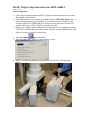
2. If the SEM software is not running, start SEM Software (SEM Main Menu icon). It
takes several minutes to start, be patient. If you need to log into computer use the
account (USER:jeol;PASSWORD:jeol). Please do not log into other accounts. Use
portable media, ftp, or UIUC NetFiles to transfer your data.
3. Prepare your samples before venting! Please keep the area clean, organized, and wear
GLOVES!! Anything that goes in the vacuum should be clean and handled only with
gloves or tweezers; keep the vacuum clean.
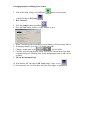
4. Press the Sample
button on toolbar.
5. Press the Vent button; it takes a couple minutes to vent.
6. When Vent light stops blinking (main panel near key switch), slide open stage
drawer.
7. Slide sample holder onto stage dovetail. Note proper direction to slide on “dovetail”
relative to step on stage platform.
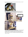
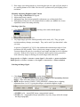
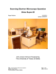
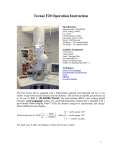
8. Adjust sample height (Working Distance) using height gauge. 10 mm is the EDS
working distance. Bottom end of ruler corresponds to the working distance (see
photo). Adjust the ruler position in the height gauge for desired working distance.
Ruler Adjusted for
10 mm Working
Distance
No part of the sample should extend above the ruler end. A 10 mm W.D. should
be used for nearly all work except low magnification imaging or if you need to tilt
more than 15 degrees. Working distances up to 48 mm can be used to attain
magnifications as low as 5x and/or better depth of focus. Working distances shorter
than 8 mm should never be used! A barrier has been installed to prevent inserting a
sample set too high.
9. Specimen tilting is limited by working distance and specimen diameter. The IR
chamber-scope must be used for sample tilting and Z adjustment to verify that safe
clearance with detectors, etc. is maintained. Safe clearance is at least 5mm distance
on LCD monitor. The following table shows the typical Allowable Tilt Range for
samples up to 32 mm diameter. Larger samples are more restricted. This assumes no
part of sample is higher than indicated Working Distance.
Working Distance
10 mm
15 mm
20 mm
40 mm
48 mm (max W.D.)
Allowable Tilt Range
0 to 15 degrees
-10 to 15 degrees
-10 to 35 degrees
-10 to 65 degrees
-10 to 70 degrees
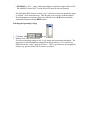
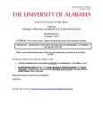
Note: The Backscatter detector and SE detector are very delicate and will be
damaged by any contact with a sample (>$3000 to repair). You must be extremely
careful not to contact these when observing your sample!!!
Conical
objective lens
Backscatter
detector
SE
detector
10. Turn on the IR chamber-scope, if off, using the switch (button) on the control box and
a switch on CRT monitor and adjust illumination as needed. Always use chamberscope for tilt and Z adjustment of sample during operation. Note: The chamberscope illumination does not interfere with SEI but must be turned off for BEIW
modes and EDS operation.
11. Carefully (slowly) slide the stage drawer closed, while verifying safe clearance of
sample on chamber-scope. Press EVAC button on the Specimen exchange dialog
box. Hold the door closed until pumping starts (it takes a few seconds).
12. In about 1.5 minutes, the HT icon turns to HT ready.
Wait at least 2 more additional minutes!!
13. Select the desired accelerating voltage (up to 30 kV)
.
Double click on new value to change setting.
14. Set the working distance (similar to previous step). Just select the working distance
you preset the sample for (usually 10 mm).
15. Set the Signal to SEI
, if not already
(You can change it to BEIW, if desired later).
16. Click the HT Ready
icon to turn on the High Voltage, now should be
Some intensity should be seen in the image window. If not press View
and
ACB
. ACB takes several seconds to run. Something should be visible on the
screen now.
17. Click the Gun icon
. The electron gun and alignment dialog appears.
There are a couple of options at this point depending on skill level, needs, etc.
Basically you need to check gun alignment and then filament saturation.
Recommended Procedure: Manually perform this task. It only takes a minute and
will insure optimized operation and best images. Note: We do NOT use Auto filament
heating or Auto Gun Control. We found the use of these seem to shorten filament life
significantly.
a. Select an area on the sample or sample holder that has reasonably
homogeneous brightness at moderate magnification (1-5 kx)
b. Adjust Tilt X and Y for maximum average image brightness at a low Spot
Size setting (<=20) by iteration.
c. Adjust Shift X and Y for maximum average image brightness at a high Spot
Size setting (=>60). ACB or manual adjustment of brightness/contrast will
likely be needed as the image brightness will usually saturate. If intensity
disappears before reaching Spot Size 60, adjust shifts at highest spot size
you still have an image, then increase to above 60 and adjust again. Again
iterate controls to optimize.
d. Steps b and c can be iterated to optimize alignment. This is usually not
necessary unless large adjustments in the first pass were required.
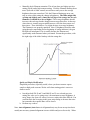
e. Manually check filament saturation. This is best done at a higher spot size
setting (40-60) and a high contrast setting. Click the Filament Heating down
arrow (left side of slider control) several times until you see the average
brightness decrease somewhat. Click the Filament Heating up arrow one
step at a time while noting the change in brightness. The slider might fully
overlap and slightly past (<1mm) the left edge of the orange bar for new
filaments. It should never be set higher! The average brightness should
increase with each step but the change between steps decreases. At the step
where there is virtually no perceptible increase, click the down arrow twothree times. There should be a very slight decrease in average brightness.
The filament is now properly saturated. Note: If brightness decreases after
going through a maximum (before beginning of orange indicator), the gun
tilt/shifts are misaligned. This is usually because the filament was
significantly under saturated when you started. Restart the procedure, with
the right edge of the slider lined up with the orange bar.
Quick and Simple Modification:
Simplified procedure, especially useful, where you do not want to expose
sample to high probe currents. Works well when starting point is correct or
almost correct.
a. Just adjust both Tilt X and Y and Shift X and Y at a selected spot size
setting (the value you’re going to use) for maximum average brightness. A
noisy image (low spot size values), however, makes this more difficult. You
could increase the averaging in the scans setup dialog to decrease the noise
but remember the response time will be slower.
b. Perform step e above.
Note: Auto Alignment (Auto button in Alignment box) may be run at any time but is
usually not necessary (manual alignment is more reliable and just as fast to do). When
running auto alignment first select an area on the sample or sample holder that has
homogeneous brightness at moderate magnification (1-5 kx) to get the best beam
alignment.
18. Select a spot size, usually initially between 30 and 40. Click
get dialog box with slider control. Usable range is about 10~75.
to
19. If desired, chose a pre-defined Recipe to set microscope conditions
(you may
switch to LV mode by selecting an LV recipe). This is a very good way to set
appropriate SEM parameters if you don’t know what you want.
Select the desired recipe and click execute.
{sets fast scan (same as Scan 2) at very low magnification (30X)}.
20. Click View
At this point, you could also select Scan 2 and move stage to area of interest an select
a relatively low magnification (features still visible although they may be out of
focus).
21. Click ACB
(auto contrast brightness).
22. Focus and check the objective aperture centering, especially for high
magnification work.
23. Fine focus and correct the astigmatism the image manually or click Auto Focus
or Auto Stigma
(auto focus and auto stigmator). On many samples
auto focus and auto stigmate actually will fail or will not be exact. Usually you need
to manually focus and stigmate especially at higher magnifications. Almost always
you need to fine tune focus and stigmators manually!! These functions are, of
course, available on the knob pad. You also need to check and, if needed, adjust the
objective aperture centering. See the next step and individual procedures in the rest
of the manual for details on how to perform these operations.
24.
Observe your sample
a. If the image shifts when manually focusing, align the objective aperture.
Adjusting this will always cause the astigmatism correction to change!
b. If the image focuses asymmetrically or with stretching or streaks, correct the
astigmatism.
c. Hint: For easier operation, in HV mode, use the SEI detector to set up the
instrument and focus, etc. Switch to the BEIW mode mostly to look at or record
slow scan images.
d. If you are working at high magnification, select a smaller spot size for a sharper
image. If the image is too noisy select a larger spot size. Remember there is a
trade off between noise (fast scanning) and attainable resolution.
e. Tilt and Z must be adjusted only if you are sure it is safe to do so (do not run
into detectors!!). Use the IR chamber-scope always for these adjustments!!
f. Scan Rotation is available (SRT icon). This is very useful for orientating the
image the way you want without rotating the stage (be aware the perception of
the image can change due to the apparent direction of oblique illumination
changing (relative position of the detector). It is also very useful for working
with cross-section samples (changing the orientation of the tilt axis).
g. Watch out for Tools Æ Neutralizer being checked. When neutralizer mode is
selected the voltage on the collector grid is changed. This mode reduces
secondary electron collection of the lowest energy electrons and may help with
some kinds of charging artifacts.
h. Many commonly used functions are available on the knob panel (magnification,
brightness, contrast, stigmator x and y, image fine shift x and y, scanning mode,
and auto functions {focus, stigma, contrast brightness}).
i. Scan4 (80 seconds) will automatically freeze at end of frame to save image.
While scanning the image observed is just a preview, the actual image quality is
much better (just watch the image as the scan finishes, then press the Zoom
button)
j. Scan3 (10 or 20 seconds) will freeze at end of frame if freeze is clicked.
k. Photo (160 seconds) can be used to decrease noise and get the best possible
quality.
l. Saved images are 1280 x 960 pixels.
For Scan3 the images are 640 x 480(10 sec) or 1280 x 960 (20 sec pixels).
m. In the Save Image dialog box there is a check box, Merge Text. When this is
checked the saved image will have the data area text embedded in the image.
n. Displayed images are 640 x 480. Click Zoom on frozen image to see full
resolution image (1024 x 768) or (1280 x 960 with pan).
o. Measuring functions are available under the Image menu for a frozen image.
The measurements can be burned into the image with the Write button prior to
saving the image.
p. SIS AnalySIS software (on SEM computer) can be also used to do image
measurements.
q. ImageJ (Java version of NIH Image) is free software which also can be used
for image analysis on your own computer.
Changing Samples or Ending Your Session
1. Turn off the High Voltage (click HT On
it should change to HT ready
2. Wait 2 minutes!!
control on main panel,
)
3. Press the Sample button on toolbar.
4. Press the Vent button; it takes a couple minutes to vent.
5. When Vent light (on the main chassis) stops blinking, slide open stage drawer
6. If changing samples, go to step 7 of general operation
7. Change vacuum mode to HV
, if in LV mode.
8. Carefully slide the stage drawer closed. Press EVAC button on the Specimen
exchange dialog box. Hold the door closed until pumping starts (it takes a few
seconds).
9. Fill out the instrument log!
10. Wait until the HT icon turns to HT ready (about 1 min. 30 sec)
.
11. You can now leave. Lock the door and turn off the lights, as appropriate.
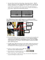
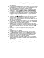
Aligning the Objective Aperture
1. This procedure needs done if the image shifts in any direction when going through
focus.
2. Center a distinct feature in the field of view (>5000x)
(the image should now modulate in focus) and Scan1 is
3. Select Wobb
automatically selected
4. Adjust Aperture X and Y controls to minimize lateral motion of feature.
Hint: Determine what direction one of the translation controls has the most effect by
over-adjusting a little and then adjust so that the residual motion is perpendicular to
that direction. Then adjust the other translation control. Iterate to fine tune. Correct
any severe astigmatism (see below) to be able to better fine tune
Objective
aperture X and Y
adjustment knobs
5. Deselect Wobb
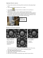
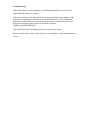
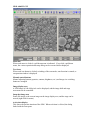
Manually Correcting the Astigmatism
Above: sequence of
images at under-focus,
near focus, and overfocus conditions with
significant objective
astigmatism
1.
2.
3.
4.
Left: An image in
focus and fully
corrected
astigmatism
Note: You need an image with edge features in nearly all directions! If necessary
find a feature on your sample, such as a dust or contamination particle
Select Stig on Knob Panel (lights green)
Adjust X and Y control knob on panel for best image
Adjust focus for best image
Iterate steps 2 and 3 until your satisfied the image cannot be improved more.
5. If the image is not sharp enough, try decreasing the spot size, and verify the sample is
at a working distance of 8-10mm. Also lower kV operation will yield slightly poorer
resolution.
Manually Adjusting Brightness and Contrast
1. Deselect Stig on Knob Panel if lit green
2. Adjust using rotary controls.
3. Adjustment may also be done manually with mouse (see software help files)
4. If Brightness/Contrast is far off (saturated black or white) use ACB to do a coarse
adjustment, before fine tuning manually.
Selecting a Spot Size
1. Click Spotsize
(A dialog with a slider should appear)
2. Adjust slider to desired spot size
3. Very high (large) spot sizes should generally not be used (>60). They give poor
resolution and may damage your sample. They can be used if you know that’s what
you want.
A spot size of around 10 @ 30 kV is the condition the instrument provides it’s best
resolution (100 kX possible). This is a fairly noisy image even on a Au/C sample.
You must choose the spot size according to your sample and what level of resolution
you need. With too low of spot size you may be unnecessarily forcing yourself to
work with noisy images or having your saved images with extra noise.
Large spot size => higher e- current => more signal => less noise => poorer resolution
Small spot size => lower e- current => less signal => more noise => better resolution
Selecting the Image Signal
1. Click Signal
to get the dialog,
.
Double Click on BEIW (backscattered electron image) or SEI (secondary electron
image). None of the other choices are currently used.
2. BEIW has three modes (COMPO, TOPO, SHADOW). Shadow has a weighting
adjustment from 1 to 10. 10 giving the oblique c element the highest weight.
a. COMPO (a+b) – normal BSE image, compositional contrast
b.TOPO (a-b) – topographical image, potentially very noisy image unless the sample
has large topography
c. SHADOW (a+b+c) – image with strong oblique component, image similar to SEI
but with BSE, needed for LV mode where SEI detector does not function
The Solid State BSE detector is fairly “slow”, therefore at fast scan speeds the image
is “blurred” in the raster direction. This does not occur at slower scans but makes
focus/astigmatism correction a little more difficult to do. ACB and manual knob
adjustment function in all the BEIW modes
Selecting the Operating Voltage
1. Click Acc. Volt
to get
2. Double Click value to be selected
The best accelerating voltage to use is very sample and information dependent. The
appearance of and information contained in an image taken at 1-5 kV can be very
different from the “same” image at 20-30 kV. This is especially true for imaging low
density (e.g. porous) and/or low-Z (atomic-#) surfaces.
Changing the Vacuum Mode
LV mode is generally used to observe and analyze non-conducting sample without
the need for a conductive coating (Au/Pd or C).
1. Turn off the Beam, i.e. Click
2. Click Vac. Mode
A dialog box confirming the change of mode should appear.
.
3. Click OK
4. When switching to LV mode, a Low Vacuum Control Dialog box appears.
.
5. An operating pressure of 1 to 270 Pa (2 torr) can be selected.
re-appears, click it to restore the e-beam (
)
6. When HT Ready
LV mode can be used to look at and analyze uncoated non-conductive samples
without charging artifact and imaging problems. It can also be used to observe wet or
badly out-gassing samples, but this requires addition procedures (wet). In general,
use as low as pressure as possible that works for imaging the sample (1 to 10’s of Pa).
Again BEIW-Shadow mode provides secondary electron like images. Since the ebeam will interact with the gas in the specimen chamber, increasing pressure will
result in a signal decrease and the resolution will get poorer. Also, longer working
distances generally will not work well in LV mode.
Starting with LV vacuum mode (sample is not suitable for HV vacuum mode)
Change mode to LV before pressing EVAC. Automatic gun alignment functions do not
function in LV mode. Strongly suggest verifying proper operation/alignment in normal
HV mode first (even if it is just on the stage, i.e. no sample)
Improving Depth of Focus or Obtaining Lower Magnifications
Move sample to a longer working distance.
Troubleshooting
If the SEM software is not responding or is behaving abnormally you can close the
application and restart it (PC-SEM).
If this does not work or the computer is locked up you can reboot the computer. If the
computer is responding use the software restart (START Menu). If the computer is
locked press and hold the power button on the front of the computer until it turns off.
Release the button then press it again to restart the computer.
(USER:jeol;PASSWORD:jeol).
This should fix nearly all problems unless there was an actual failure.
Do not cycle the power on the entire system (key switch) unless a staff member instructs
you to.
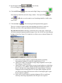
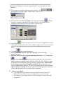
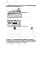
JEOL 6060LV GUI
Menu bar
When each menu is clicked, a pull-down menu is indicated. If you click a pull-down
menu, the various operation and setup dialog can be executed and/or displayed.
Text icons
When each icon button is clicked, switching of the scan mode, auto-function is started, or
an operation window is displayed.
Manual control buttons
Manual adjusting buttons (spotsize, contrast, brightness, etc.) and image size switching
button are arranged.
Image display area
A SEM image of 640×480 pixels can be displayed, and the image shift and stage
movement can be controlled.
Snap shot image area
Pastes file image or the current image on the image display area, and the stage can be
moved (right click for menu)
Active data display
This shows the present situation of the SEM. When each item is clicked, the dialog
linked with the item opens.