1
ER45e
Quick Start Guide
E-Series Ethernet Radios
Step 1 - RF and DC power connection
Step 3 - TVIEW+ Management Suite
Step 4 - Checking RF Link
RF Connection
To simulate a long distance RF link on your test bench, the recomended
method is to use RF attenuators. RF attenuators are far superior to antennas
for short-distance bench testing as the attenuation of the RF signals
between both radios is consistent and is not subject to external Interference.
Alternatively 90dB of separation can be achieved with 50 ohm dummy loads
or small whip antennas (minimum separation 1m (or 3ft).
TVIEW+ Management Suite allows a number of features including:
Configuration (Local - Serial, or over-the-air) and Remote Diagnostic
Facilities.
The RF link can be checked by energising the transmitter of your master
radio. To energise the transmitter review the instuctions in Section 6.
(1) If the TX power of each radio is set to 20dBm (100mW) low power,
low cost attenuators can be used.
Step-by-Step Point to Point Setup
Introduction
This document describes the 5 key steps required for configuring the
radio and demonstrating Modem operation and communication overthe-air on a pair of factory default, ER45e half duplex radios operating
in Point to Point ( PTP ) mode. After successful testing is achieved,
subsequent testing can then be done on user equipment such as RTUs
or PLCs.
For more information consult the following documents:
- ER45e E-Series Ethernet User Manual
Now that the transmitter has been energised on your master radio take a
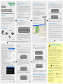
look at the LED indicators on the MASTER unit. They should look like Fig 14:
The configuration wizard can be used to provide Quick Start generic
templates fo the types of system architecture you wish to employ.
Example: Local configuration session -
Fig 14
1) Launch TVIEW & Select “Programmer”
2) Ensure radio is powered up and ready as described in Step 2.
The SOLID RED LED indicates that the units transmitter is energised.
(2) Ensure the signal into the receiving radio is no greater than -30dBm
(set Tx power on all radios to 20dBm).
3) Attach the programming cable from the PC to the system port of a radio.
Ensure you DO NOT connect the programming cable into the LAN port.
as for the REMOTE unit, the LED indicators should look like Fig 15:
DC Power Connection
Ensure each radio is wired using the correct polarity and that power
supply is regulated and has adequate current delivering capacity.
4) Select “Read” to read the Local Radio
5) Select “Wiazrd”
Fig 15
6) Select “PTP Half Duplex Link”
The SOLID GREEN sych LED indicates the the receiver is synchronised
7) Adjust Tx Power to 20dBm
Step 2 - Power Up Radios
Once completed, turn off the Transmitter on the MASTER and energise
the Transmitter on the REMOTE unit, verify correct LED operation.
8) Configure and save IP Parameters and frequencies
Nominal Operating voltage: 13.8V DC (Filltered)
Transmit Current: 750mA nom @ 1W, 1700mA nom. @ 5W
Receive Current: 150mA nom
Rated Operating Voltage 10 - 30 Volts DC
9)Select “Write”
Step 5 - Verify Modem Operation
Repeat 2-8 on slave radio.
Now that you have verified an RF link you should verify you can
communicate between each ER45e. To do so you should perform a
‘Ping Test’.
- TVIEW+ Diagnostics User Manual
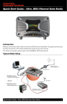
Typical Radio Setup
1) Ensure the ER45e is powered and has fully booted. This is indicated
by a solid green power LED. It takes about 45 seconds for the radio to
fully power up.
Fig 12
9
4) Ensure your PC LAN port is configured for a suitable IP address.
You can do this by configuring the LAN settings via the control panel.
Navigate to your windows “Start” button and open Control panel ->
Network Connections -> Local Area Connection -> Properties. Scroll down
and select “Internet Protocol (TCP/
IP)” then click on Properties. You
should now see a window shown in
Fig 16. Ensure “Obtain IP Address
Automatically” is NOT selected. It is
recommended that you manually
specify a compatible IP address. In this
example, we are performing a ping
test on a factory default radio. The IP
address of the radio is 192.168.2.15
and a compatible IP address for the
PC would be 192.168.2.1. Click OK to
accept the changes.
Note: Check with your system
administrator before allocating IP
addresses as each LAN/WAN network is different.
Fig 16
5) Open up a command window on your PC by going to the “Start”
-> Run and typing “CMD” then OK. Then type “ping 192.168.2.15”
(Example: this is the
default address of the
radio). If both the radio
and PC have their LAN
port connection and
configuration correct, the
radio will respond to the
ping as shown in Fig 17. If
this is not the case, check
Fig 17
you network settings as described in the previous step.
6) Once successfully completing the ping test with your locally
connected radio, stay locally connected to the same radio, but now ping
the IP address of the remotely connected radio. If all connections and
configurations are correct, the remote radio will respond in the same way.
13
2) Disconnect your PC from any other internet/LAN networks. Failure to
do so may cause a conflict in IP addresses or the ER45e might not meet
the subnet mask specified by your network.
Apply DC power to the radios. The “Pwr” LED should now be solid GREEN.
Wait for 30 secs before attempting to read the unit with the programmer
(During boot, other LEDs may flash). If there is no LED indication, the
internal fuse may have opened. Re-check the DC polarity and ensure
the DC voltage is between 10V and 30V. Also check that you have NOT
plugged your units system port into your LAN/WAN, as this will also cause
all LED indicators to turn off.
3) Connect your PC Ethernet port to the units LAN port using an
RJ-45 Patch cable. Cross over cables will also work. Successful cable
connection is indicated by a solid Green “Link” LED on the LAN port.
Note: The LAN port will also flash amber when data is being transfered.
Fig 13
10
LED Indicators
DC Power :
If all the LEDs are off, no DC power is reaching the radio modem or the
internal fuse is open. Successful power-up is indicated by the Pwr/Tx
LED showing a continuous GREEN state.
LAN PORT:
The “Active/Link” LED is used to indicate the state of the LAN port. If the
LED is OFF, there is no activity at all on the LAN port. A GREEN indication
shows an established Ethernet link (See Fig 21). The LED will flash AMBER
to indicate Ethernet data transmission is occurring (See Fig 22).
(Established Ethernet Link)
Note: The ER45e radio will take approximately 45 seconds to boot up
- during this time, other LEDs may flash. After the unit has fully booted,
the DC power LED will remain solid green. (See Fig 18)
(ER45e Powered up)
11
12
Important Notices for Class 1, Division 2
Groups A, B, C & D Hazardous Locations
Applies to models ER45e-xxxxx-xHx(CSA Marked)
This product is available for use in Class I, Division 2, Groups A, B, C & D Hazardous
Locations. Such locations are defined in Article 500 of the US National Fire Protection
Association (NFPA) publication NFPA 70, otherwise known as the National Electrical Code
and in Section 18 of the Canadian Standards Association C22.1 (Canadian Electrical Code).
The transceiver has been recognised for use in these hazardous locations by the
Canadian Standards Association (CSA) International. CSA certification is in accordance
with CSA Standard C22.2 No. 213-M1987 and UL Standard 1604 subject to the
following conditions of approval:
Fig 21
(Ethernet transmission occuring)
1. The radio modem must be mounted in a suitable enclosure so that a tool is required to
gain access for disconnection of antenna, power and communication cables.
Fig 18
Received Signal Indicator :
The “Rx/Synch” LED is used to indicate the state of the receiver. If the
LED is OFF, no signal is being received. A RED indication shows that
an RF carrier is being received but no data can be decoded. this may
indicate the presence of interference, another user on the channel or
an illegal user. (See Fig 19)
Fig 22
Data Port:
The RxD/TxD LED indicates data flow in/out of the data port. Data being
sent to the port for transmission is indicated by a RED flash, and data
being received over the air and then sent from the port is shown as a
GREEN flash (See Fig 23).
Error LED Indications:
(Receiving decodable data)
Fig 20
14
4. Tampering or replacement with non-factory components may adversely affect the safe use
of the radio modem in hazardous locations and may void the approval.
WARNING EXPLOSION HAZARD
Fig 23
A continuous GREEN indication shows that the modem is locked
and synchronised to the incoming signal (See Fig 20). Any loss of
synchronisation (BER Errors) is indicated as a visible RED flicker of the
LED. (See Fig 19)
3. Installation, operation and maintenance of the radio modem should be in accordance with the
radio modem’s user manual and the National Electrical Codes.
5. A power connector with locking screws as supplied by Trio Datacom MUST be used.
(Serial Data sent out of the Data Port)
(Receiving un-decodable data)
Fig 19
2. The antenna, DC power and interface cables must be routed through conduit in
accordance with the National Electrical Codes.
In some circumstances the radio will indicate an error state. This is shown
as all LEDs flashing RED for 1 sec and then a pattern of green or amber
LEDs for 1 sec. The pattern of green or amber LEDs indicate the type of
error. Please consult the user manual for further information.
Support Options - E-mail Technical Support
When e-mailing questions to our support staff, make sure you tell us the
exact model number (and serial number if possible) of the TRIO Datacom
equipment you are working with. Include as much detail as possible about
the situation, and any tests that you have done which may help us to
better understand the issue. If possible, please include your telephone
contact information should we wish to further clarify any issues.
15
Do not disconnect equipment unless power has been switched off or the
area is known to be non-hazardous. Substitution of components may impair
suitability for Class I, Division 2. Refer to Articles 500 through 502 of the
National Electrical Code (NFPA 70) and Section 18 of CSA C22.1 for further
information on hazardous locations and approved Division 2 wiring methods.
Contact Details
Technical Support: The Americas
Available: Monday to Friday 8:00am - 6:30pm
Eastern Standard Time
Toll free within North America: 1-888-226-6876
Direct Worldwide: +1 (613) 591-1943
Email: [email protected]
Technical Support: Asia Pacific
Technical Support: Europe, Africa,
Middle East
Available: Monday to Friday 8:30am - 5:30pm
Central Europe Standard Time
Direct Worldwide: +31 (71) 579 1655
Email: [email protected]
Available: Monday to Friday 8:30am - 5:30pm
Australian Eastern Standard Time
Direct Worldwide: +61 3 8773 0100
Email: [email protected]
Issue : 06-11
Printed in Australia