1
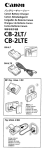
Hnmalnvartar
1600W-3500W
USER MANUAL
Pure Sine Wave Home lnverter
Table of contents
l . Introduction
1.1 Introduction of Inverter···················· .. ····· ······················ 01
1.2 Important Safety Instructions········· ···························· ··· 02
1.3 Indicator and Setting ··· ·····... ..... ..····· ·········· ...... ... ·········· · 04
2. Installation and Operation
2.1 Installation ···· ····...... ······.. .. ··........ ······.... ······.... ······... ···· 09
2.2 Installation Diagrams ................... .. ............................... 11
2.3 Installation Steps .... ................... ......................... .. ........ 12
3. AC mode
Thanks for using our products.
Please strictly obey all the instructions in
this manual and pay attention to all the
warning and operation information. It is not
advisable to install or operate the machine
before reading this manual.
3.1 How to change the battery in AC mode ....... ....... ............. 12
3.2 Transfer Switching Speed .............. ................................ 12
4. Battery
4.1 Battery Size ·........ ··...... .. ....... .. ........ .. ............................ 13
4.2 Monthly Maintenance .................................................... 14
4.3 Battery Hook-up Configurations ...................... ............... 14
4.4 Battery Installation ................ ............ ........................... 15
5. Technical Specification ...................................................... .... 17
6. Troubleshooting ............................. ......... .. ....... ....... ............. . 17
7.Service and Support ......................................................... ..... 18
1 Introduction
1.1 Introduction of Inverter
l.The Heme Inverter not only is an inverter but al so contains a
powerful smart charger.
2. The Heme Inverter can generating pure sine wave frem a 24V- battery
bank, which can supply energy te varieus loads such as resistive load
(heater),inductive load (air conditieners, refrigerator),motors (vacuum
cleaners), and rectifier load (computer). All Heme Inverter are designed to
work in heavy load condition. De-rating is not necessary.
3 .The smart charger work with three steps charge way in arder to
improve the battery life. Clients can set the charging current and
voltage according to the battery type and capacity. Efficient highpower charging current, the battery can be quickly recharged. The
switch module automatically diverts the energy transfer path between
inverter and utility source. When the utility source is lower than the
transfer level, the path switches to battery mode. Otherwise the
load is conducted to the utility source. The transfer time is 1/4 .... 1/2
of the total cycle time. The high power charger (BOA) can charge a
24V/1000 AH battery bank in 14 hours. By the way, the inverter can
work with generator which can prolong the battery lite.
1.2 Important Safety Instructions
1.2.1 General Precautions
l. Before using the Home II'M:!rter, please read all instrudions and cautionary marks on
<D the inverter,
® the batteries
® all appropriate sections of this instruction manual.
2 .Do net expose Heme Inverter to rain, snow, or liquids ef any type.
The Heme Inverter is designed fer indoer mounting only. Protect the
inverter from splashing if used in vehicle applicatiens.
3. Do not d isassemble the Home Inverter; take it toa q ualified service
center when service or maintenance is required. Incorrect re-assembly
may res u lt in risk of electric shock or fire.
4. To reduce risk of electric shock, discennect all wi ring befare making
any attempt to maintain or clean. Simply turning off the inverter will
net reduce this risk.
Wa~ng!
AA
Working in the vicinity of a lead acid battery is dangerous;
Batteries generate explosive gases during normal operation.
4. Heme Inverter can also work in mains mode (AC input normal) without
5. Provide ven ti latien to eutdeors from the battery compartment. The
battery enclosure sheuld be designed to prevent accumulation and
cencentratien of hydrogen "pockets" at the top ef the cempartment.
battery, and battery can be replaced with the machine on. Visible and
Vent the battery compartment from the highest point. A sloped lid
audible LCD display and buzzer can help users understand the working
condition of machine, battery and mains condition, quickly determine
varieus failures, to improve work efficiency.
can al so be u sed to direct the flow threugh the vent opening location.
5. Heme Inverter is an extremely good choice for utility back up power.
However, it also can be used as a UPS for computers.
6 .An inverter, charger and switching box can be replaced with a single
Heme Inverter unit
6. Never charge a frozen battery.
7.Shuck off 10-12mm insulated cable from AC cable,15-20mm cable
from the DC cable. In arder to connection with inverter well. Be
extra cautious when working with metal tools on or around batteries.
The potential of dropping a tool causing the batteries or other
electrical parts resulting in sparks could cause an explosion.
01/02
8. The inverter must be used with a battery supply of nominal voltage
8.In well connected system, if repairing related equipment (such as
that matches the last two digits of the model number; e.g. 24 volts with
a Heme Inverter 1600W, Heme Inverter 2500W, Home Inverter 3500W.
electricity, generators, etc.), make su re that the inverter and other
equipment has been completely closed, to avoid accident s.
9. Grounding instructions. This battery charger should be connected toa
grounded, to insure safe, permanent wiring system. For most
installations, the negative battery conductor should be bonded to the
1.3 Indicator and Setting
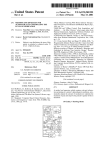
1.3.1 Map of Controls and LED/LCD Indicators and buzzer
grounding system at one, and only one, point in the system. All
Shown below are the control panel and indicator lights on the front
installations should comply with all national and local cedes
of the Heme Inverter. These controls can provide information in eit her
and ordinances.
inverter or battery charging mode of the operation. All models of
the Heme Inverter series operate identically.
1.2.2 Personal Precautions
l.Someone should be within voice range when you work near batteries
in case of an emergency.
2 .Have plenty of fresh water and soap nearby in case battery acid
contacts skin, clothing, or eyes.
3 .Wear complete eye and clothing protection. Avoid touching eyes
while working near batteries. Wash your hands when done.
LED and Alarm Indicator for 24V system
4 .If battery acid contacts skin or clothing, immediately wash with soap.
If acid enters eyes immediately, flood eyes with cool, running water
for at least 15 minutes. Immediately seek medical attention.
5 .Never smoke or allow a spark or flame in the vicinity of a battery
or generator, to avoid fire .
6 .Be extra cautious when working with metal tools on and around
AC mode
On
Off
Beep once
Battery mode
Flashes 1/ 2 sec
Off
Beep once
ECO
Flashes 1/4 sec
Off
Off
Self- test
Flashes 1/1 sec
Flashes 1/1 sec
Off
Low battery
Flashes 1/ 2 sec
Flashes 0.5/sec
Beep 1 @ 0.5 sec
AC h igh voltage
Off
On
Beep 1 @ 0.5 sec
Charger off
Overload 110%
Flashes 1/ 2 sec
On
Beep 1 @ 0.5 sec
Output off after 15min
Keep on beeping f or 60s
Output off alter 60s
Boot
Overload 120%
Flashes 1/ 2 sec
On
Overload 150%
Flashes 1/ 2 sec
On
Press confinm buttoo
No change
No change
Battery mode,
output short circuit
Off
On
Keep on beeping f or 60s Output off immediat ely
Ballay mode cmr temp
Off
On
Keep on beeping f or 60s Output off immediat ely
AC mode 0\/el' temp.
On
On
Keep on beeping f or 60s charger off immedlately
a short -circuit current, which is high enough to weld a ring or the
Over current
(ACmode)
Off
on
Keep on beeping f or 60s
like to metal causing severe burns.
System fault
Off
On
Keep on beeping f or 60s
batteries. The potential of dropping a tool causing the batteries or
other electrical parts resulting in sparks could cause an explosion.
7 .Remove personal metal items such as rings, bracelets, necklaces,
and watches when working with a battery. A battery can produce
Keep on beeping for 60s Output off immediat ely
Beep once
Output and charger
off lmmedlately
03/04
>>Power Switch
The Power ON/OFF button is located in the left of the panel. Once the
Home Inverter has been properly installed and the batteries are connected,
please press the button to power the Home Inverter for 3s. This will
alternately turn the Home Inverter on and off. When the button is
depressed, the buzzer will beep to announce that the button is being
pushed down. Depressing the switch will toggle the working stage
lo 1u1~ 1: 1 ~ 1~ 1a1: 1 t 1a1 ~ 1 ~ 1~ lsl 1 z1
H
1 n 1: 1
1
~ ~
1
1 V 1 a 1 : 1 t 1a 1
~ ~ ~
1
1
1 91 H 1 z 1
®Bypass Mode
between on and off.
IBIYIPia ls lsiiMIOid
Note:
l.When connected to batteries, the Home Inverter will begin the
process without AC source input. The Home Inverter can be
activated by pushing the on/off button.
2.When there are no battery connected, but the AC was normal, The
Heme Inverter can work in utility mode by pressing the button.
>>LCD display information
lncluding AC mode, battery mode, generator mode, checkthe information
1° 1 u 1
~
1
1: 1
1° 1 u 1
11"
IUitlilliltiYIIIMioldlellll
lo 1
u 1t 1
P1 1 t lsl: 1; 1: 1 e~~ 1
u
a 1t 1
t 1 s1
~~l:l~l:l~l~l~l~ll~l:l~l:laiQiel
lB ~~ ~~ r lsl~l: ~~~ r ~~ ~~~
1:
1:1
1:
1:
1;
1
lsl: 1~ 1: 1 ~~ 1 a1 t 1 t 1 s1
9
u 1t
~ ~
1: 1
1 : 1nn 1
~ ~ ~ la
1
1
1: 1
1:
1g 1e 1
lB l:lstl; 1:1 r~~~g~~ 1:1:1 rl:l~ 1; ~~ ~
with up and down button.
@ACmode
t 1P 1
9
1 11111
~ ~ ~ a t a ~ ~ ~ lsl
1: 1
1
1
1: 1
1
1
1
1
H 1z 1
l:l~l~lvlal!ltlal~~~~~~siHiz l
@Generator mode
IGielnlelrlaltlolriiMioldlell l
1° 1 u 1 t 1 P 1 u 1 t
~
1
1: 1
lsl: 1~ 1: 1 e~~ 1 a 1 t 1 t 1 s 1
~ ~ ~ ! ~ ~ ~ ~ la
1
1
1
1
1
1
1
1: 1
1:
e1
19 1
05/06
l:l:l;l~lel;l~l.l~l~l al:l:l9¡ ~~~g~
1° 1u1; 1: 1~ 1~ 1a1: 1t 1a1~ 1~ 1~ 19 1H1z 1
11"
l:l~l;lvlal:ltlai~I~I~I91HIZI
>>ECO mode operation
Press 8 a nd@ for 2s, inverter will go to ECO mode. (load must be less
than 20w,presseand@again for long time, itwill quit ECO mode.
The ECO mode was used in battery mode, this function was used for
avoiding unnecessary discharge without load. When load over 30w,
it will back to normal.
>>Self-test
When inverter working,"self-test "will show on LCD while red/green
LED flashing.
®Battery mode
1
9
1 1n 1v 1e1r 1t le 1r 1 1M 1° 1d 1 1 1 1 1
1 1a1~ 1~ 1~ 1~ 1: 1d 1~ 1t 1a 1~ 1~ 1: 1% 1 1
8
1° 1u1t 1P 1u1t 191: 1: 1: 1e~~ 1a1t 1t 1s 1
1° 1u1; 1: 1~ 1~ 1a1: 1t 1 1~ 1~ 1~ 191 H1z 1
> >Setting mode
Press the8 for 2s, inverter go to setting mode, red/green LED
flashing and then set the value with@and@; press the 8 to confirm.
a)Generator mode = Enable 1 Disable ( Default = Disable)
b)Battery Boost Voltage = 28"' 30.0 V DC for 24V system ( Standard=28VDC)
c)Battery Floating Voltage = 26"' 28.0VDC for 24V system (Standard=
27.0VDC )Notice: all kinds of battery voltage setting:
8
11"
Notice: all kinds of battery voltage setting:
l:l~l;lvlal:ltlai~I~I~I91HIZI
1
IPiolwlelrl 1S 1a1v 1e 1 IM 1° 1d 1e1 1
@Replace battery
1R 1e1~ 1 1a 1e1e1 IBial tltlelrlyl 1
To be used by
factory for set up
28.8
27.2
2
Gel USA
28.0
27.4
3
AGM 1
28.2
26.8
4
AGM2
29.2
27.4
5
Sealed lead acid
28.8
27.2
6
Gel EURO
28.8
27.6
7
Open lead acid
29.6
26.6
8
Calcuim
30.0
27.1
@ECOmode
07/08
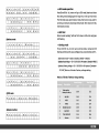
d)Charging Current = 10,..., 70A 10 A for one step (Standard 50A)
Note : please set the charging current according to the capacity of the
Generally speaking, it is a cousin to stereo equipment, television sets,
battery, high charging current will result in battery over temperature.
Please set the charging current the Min when battery is small
copper bus bars, powder coated metal components, and stainless
and computers. The use of conformed coated circuit boards, plated
capacity ; Charging voltage should be set according to battery type,
steel fasteners allows the unit to function in hostile environments.
However, in a condensing environment (one in which humidity and/or
otherwise battery will be over charged and damaged.
temperature change causes water to form on campanents) all the
ingredients for electrolysis is present- water, electricity, and metals.
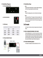
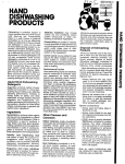
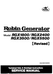
Charging pragress of battery:
In a candensing enviranment the life expectancy af the inverter cannat
be determined and the warranty is voided.
Progress
Three stage :CC(Constant current)Boost
CV(Constant voltage)Fioat(float charge}
Vde
--~- -- - - -1 --
14.0
------~:-- ----- ~ --·~·~ -----/
13.0
Cha rg ing tra nsformati o n
definition
Current %
15.0
12.0
11.0
Boost c v-r - - - - - - - - - -
t;T--- ;¡--~:::: :::.:-~
--- TI----,1
10.0
-1--------1
-------- ~ -------1---------
f---
TO
---! 1----- T1
-
100%
moisture. Exposure to saltwater is particularly destructive and
patentially hazardous.
""'
10d•y• -
o
Time
Charging voltage@ 25"C
2 .Caution: It is in yaur best interest to install the inverter in a dry
protected lacation away from sources of high temperature and
3 .Loe ate the inverter as clase as pos si ble to the batteries in arder
TO = from starting to finishing.(Constant current)
T1 = 10 x TO{Constant voltage)at least 1 hour,
Max time= 12 hours.
to keep the battery cables short. However, do not locate the inverter
User can setthe constant voltage and floati ng
be located in a compartment with sealed electronic equipment - and
voltage according to the battery.
everything else. Batteries also generate hydrogen and oxygen. If
in the same compartment as non-sealed batteries. (The inverter may
accumulated, this combination could be ignited by an are resulting
from connectian of the battery cables or by switching a relay.
2 Installation and Operation
2.1Installation
2.1.1 Environment
l.Home Inverter is a sophisticated electranic device and should be treated
carefully. When selecting the operating environment for the inverter,
do not th in k af it in the same terms as other eq u ipment that works
with it; e.g., batteries, diesel generators, motor generatars, washing
machines, etc. It is a highly complex micrapracessor controlled device.
4. Do not mount the inverter in a closed container. Unrestricted airflaw
is required to aperate at high power for sustained periods of time.
Without it, the protectian circuitry will activate and reduce the
maximum power available.
2.1.2 Grounding System
Metal shell and ground terminal have been connected inside the
machine, please cannect the ground terminal to ground, in arder to
reduce the risk of electric shock
09/10
2.2 lnstallation Diagrams
2.3 lnstallation Steps
2.2.1 Terminal Block (AC Side)
• Step 1
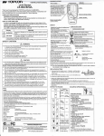
Connect the inverter with battery, AC and load according to the diagram.
Confirm all wiring connected well and terminal is tight.
• Step 2
Check all the voltage rating is correct. Close the circuit breaker.
• step 3
Press the on/off button. The system will start working after a few
seconds. If the mains power fails the unit will work in Inverter
mode. If not, the system will switch to AC mode and supply power
to load and battery.
2.2.2 Terminal (DC Side)
3AC mode
2.2.3 (Wire Gage)
In AC mode, the inverter working in bypass mode and charge the
battery
220V
220V
1600W
16AWG
16AWG
16mm2
2SOOW
14AWG
14AWG
35mm2
3SOOW
12AWG
12AWG
50mm2
2.2.4 Simple Installatlon Dlagram
PDU
IDII
11
INVERTER l CHARGER
3.1 How to replace the battery in AC mode
Please press8and @for 2s, inverter will go to battery change
mode, open the battery breaker befare replacing the battery. When
replacing the battery, make su re the battery positive and negative
was connected right. After finishing, elose the battery breaker, and
then press the a nd ® to quit the battery change mode.
e
3.2 Transfer Switching Speed
The transfer time between AC mode and battery was 16+/-4ms.
I!ARTH GROURD
11/12
4 Battery
4.1 Battery Slze
1.Batteries are the inverter's fuel tan k. The larger batteries are,
the longer lnverter can operate befo re recharglng ls necessary.
An underslzed battery bank results In reduclng battery llfe and
disappointing system performance.
2 .Batterles should not be regularly dlscharged to the llmlt of more
lttan 50% of their capacity. Under extreme a:mditions, such as a severe
storm ora long utlllty outage, cycllng toa dlscharge level of 80% ls
acceptable. Totally discharging a battery may result in permanent
damage and reduced llfe.
4 .1.1 Estimating Batteries Requirement
In order to determine the proper battery bank capacity, it is necessary
to compute the number of amp hours that wlll be used durlng charglng
c:ycles. When the required amp hours are known, the expected amp
hour usage ensures to be tw!ce as th!s amount. Doubllng the expected
amp hour usage en sures that the batteries will not be over discharged
and extends battery llfe. To compute total amp hours usage, the amp
hou r requlrements of ea eh appllance that ls to be used ls determlned
and then added together.
4.2 Monthly Malntenance
Checklng the condltlon of battery connectlon once a month (Battery
maintenance·related details, please refer to the user manual battery) •
Make sure the battery cable ls not loose, battery term!nals not corrode •
Any corrosion willlead wires disconnected, use soda water to clean,
careful not to let soda water lnto the cell. In order to reduce corroslon
of the battery terminals, battery terminals should be smeared with a
thln layer of oll olntment or antl·corroslon grease (whlch can be from
automotive supplies stores or battery suppliers get). Do not put anything
between the battery termlnals and wrres, metal should be used to
c:onnect, tighten the screws, and then attach the protective sleeve.
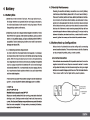
4.3 Battery Hook-up Configurations
Battery banks of substantial size can be configured by connecting
several smaller batter!es. There are three ways todo thls. Batterles
can be connected In parallel, series, or series ·parallel.
4.3.1 Series Connectlon
When batterles are connected wlth the posltlve terminal of one to the
negatlve terminal of the next, lttey are connected In series. In a series
configuration the battery bank has the same amp/hour rating as a single
battery and an overall voltage equal to the sum of ltte Individual batter!es.
This is common with 2-4 volt or higher battery·inverter systems.
If we know ltte load power W and battery voltage V and ltte needed back
up time T, we can calculate the battery discharging current I as follow:
I•W/V So
AH=I*T=W*T/V So
Needed battery capacily was 2W*T /V
Motors are normally marked wlth thelr runnlng current rather than thelr
starting current. Starting current may be three to six times running
current. Manufacturer's llterature may provlde more accurate !nformatlon
than the motor nameplate. For larger motors, increasing the battery
capaclty should be requlred.
TOTALBATTERY
BANK CAPACITY
200 AMP· HOURS
@ 24VDC
13/14
4.4.2 Battery Enclosure
24V INVERTER
TOTAL BATTERY
BANK CAPACJTY
200 AMP·HOURS
@ 24VDC
4.4 Battery Installatlon
C!lutlon: Batterfes e21n produce extremely hlgh current5 In short·clrcult.
Be very careful worklng around them. Read the lmportant safety
lnstructtons at tl!e beglnnlng of thls manual and the battery suppller's
precaulfons before lnstalllng tl!e lnverter and batterles.
4.4.1 Battery Locatlon
The battery must be as close as posslble to the lnverter, but not
hlnder to dlscon nect the lnverter. Beca use thls series lnverter DC
wlrlng termln;,lls loc:ated In theleft, so the battery ls best plac:ed
to tl!e left. Do not put tl!e lnverter wltl! no sealed battery compartment
at the same place (sealed can). Beca use the battery wlth the
generated gas ls corroslve, wlll reduce the llfe of the lnverter.
Wlrlng from the battery to the rnverter should not be too long, the
DC voltage 12V systems with 4/0 AWG wiring should not be more
th;,n 5 ft, ¡ DC voltage 24 volt system wlth a 4/0 AWG wlrlng should
be no more than 10ft.; simple and reduce losses.
To prevent access from untrained personal, batteries should be
protect:ed witl!in a ventilated, locked enclosure or room. The enclosed
should be ventllated to tl!e outdoors from the hlghest polnt to prevent
accumulatlon of hydrogen gasses that are released In the battery
charglng process. Allalr lntake should also be provtded at alow polnt
In ti! e enclosure to allow alr to enter In Ol'der to promote good ventllatton.
For most systems a one·inch diameter vent pipe from the top of the
enclosure ls ¡o¡dequate to prevent acc::umulatlon of hydrogen. A sloped
top can help dlrec:t the hydrogen to the vent loc:atlon and prevent
pockets of hydrogen from oc:c:u rrlng. The enc:losu re should al so be
c:apable of holding at least one battery c:ell worth of electrolyte In the
event a spill or leak occ:u rs. The enclosure should be made of acid
resistllnt material or have an acid resistant finish applied to resist the
c:orroslon from spllled electrolyte and released fumes. If the batterles
are located out of doors the enclosure should be ralnproof and have
mesh saeens wer any oper~lngs to prevent lnseds and rodents ti'om entemg.
4.4.3 Battery Cabling
Heavy cables should be used to connect Individual batterles to
configure a larger battery bank. The actual size of ti! e cable depends
upon whetfler the bzlt:teries are c:onnected in parallel or series. Generally,
the cables should not be smaller than the maln battery cables to the
lnverter. If the maIn cables are 4/0 AWG the battery lnterconnects
should be 4/0 AWG.
It ls usually preferable to connect the batterles flrstly In series and
then In parallel when connectlng smaller batterles, whlch would
reduce the confusion of wiring. If you want to improve battery
perform;mce, ple¡se c:ontac:t your batterv suppller, they wlll provlde
more favorable conflguratlon for your c:onnec:tlon svstem •
15/16
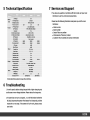
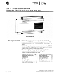
5 Technical Specification
7 Service and Support
11DDW
Battery
Input
AC input
DCvoltage
24V
OC voltage ra nge
20V-30V
Working normally
W/0 bat K. normal
Max Input current
20A
1/P voltsge range
220V(+/·10%)
AC mode output voltage
180-245V:1:5% for 220V
50Hz/60Hz (+/-0.3Hz)
Pure sine wave
0/P capaclty
1600W
2500W
3500W
Max surge protect
4800W
750DW
10500W
>80'!1.
16+/-4ms
0.8- 1.0
Yes
Yes
Yes
10-40A
10-70A
10-70A
Voltage adjusta ble
26V-30V
Charge mode
3 step-Bu lk. Boost.. Float
Display and alarm
LCD&LED&Buzzer
Worklng temp.
O'C-4D'C
Working Humldity
5%-95%RH
Fan cooling
Coolingway
Welght(kg)
Model number
Serial number
Date of failure or problem
Phenomenon of failure or problem
Customer returns address and contact information
<20W
Transfer time
Reslstance load
Current adjustable
Distributor:
•
•
•
•
•
Yes
Power factor
Inductance load
Capacitance load
Others
35A
Generator
OC mode output voltage
ECO mode
Max efficiency
Charger
25A
1/P frequency
0/P waveform
If yo u have any questions or problems with the inverter, call your Local
Distributor to ask for a technical representative.
Please have the following information ready when yo u call the Local
15SV-280V for220V
50Hz /60Hz(Auto testing)
0/P frequency
Output
35DDW
20
Dlmenslon W*L*H
22
360*600*293
23
360*630*293
Technlcal Speclflc•tlons subject to ch•nge wlthout notlflc•tlon.
6 Troubleshooting
l.A small capacity battery being charged with a higher charging rate
could cause an over voltage shutdown. Please reduce the charge rate.
2.If system does not turn on properly, turn off the breaker befare the
DC side, disconnect the system from battery for 30 seconds, and then
repeat the turn on steps. If the system still can't work, please contact
your dealer.
17/18