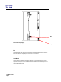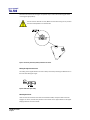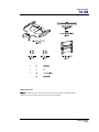
1
ASPECT TA-500 SYSTEMS
TA-500
TA-500DP
TA-500t
TA-500tDP
TA-500H
TA-500HDP
TA-500HM
USER MANUAL
Turbosound Ltd.
Star Road, Partridge Green
West Sussex RH13 8RY United Kingdom
Tel: +44 (0)1403 711447 Fax: +44 (0)1403 710155
web: www.turbosound.com
Issue 1.1 © Turbosound Ltd.
user manual
TA-500
Contents
EC Declaration of Conformity ...........................................................................................................................6
Introduction ........................................................................................................................................................7
Turbosound Aspect System Concepts .......................................................................................................7
The Aspect Polyhorn™ Concept..................................................................................................................8
The Loudspeaker Management System (LMS) Concept ........................................................................10
LMS-D2X Loudspeaker Management Systems .......................................................................................10
Network Capability .....................................................................................................................................10
Power Amplifiers.........................................................................................................................................11
Digital Controllers .......................................................................................................................................11
Self-powered Loudspeakers ......................................................................................................................11
Aspect Loudspeaker Components ............................................................................................................11
TA-500 Three-way Loudspeaker................................................................................................................13
TA-500DP Self-powered Three-way Loudspeaker...................................................................................13
TA-500t Touring Three-way Loudspeaker ................................................................................................13
TA-500tDP Self-powered Touring Three-way Loudspeaker ...................................................................13
TA-500H Horizontal Three-way Loudspeaker...........................................................................................14
TA-500HDP Self-powered Horizontal Three-way Loudspeaker..............................................................14
TA-500HM Two-way High/Mid Loudspeaker ...........................................................................................14
TSW-218 Subwoofer...................................................................................................................................14
B18 Subwoofer............................................................................................................................................15
B18DP Self-powered Subwoofer...............................................................................................................15
Transportation.............................................................................................................................................16
Flying and Stacking .........................................................................................................................................17
Flying and Stacking .........................................................................................................................................17
Overview......................................................................................................................................................17
Safety Notes on Rigging ............................................................................................................................18
Secondary Safeties .....................................................................................................................................19
Safety Inspections.......................................................................................................................................19
Sample Certificate of Load Test ................................................................................................................21
Flying Hardware...............................................................................................................................................22
Aspect TA-500 Flying Systems ..................................................................................................................22
Horizontal Coverage ...................................................................................................................................22
Vertical Coverage........................................................................................................................................22
A. TA-500t Touring Flying System .................................................................................................................23
TA-500 user manual
Page 2
user manual
TA-500
Flybar Settings ............................................................................................................................................23
Touring two-wide flybar.............................................................................................................................23
Table 1: Flying Matrix .................................................................................................................................25
FC-500T Flying Chains ................................................................................................................................25
TS-890 Tilting Straps ..................................................................................................................................27
Integral Flying Hardware............................................................................................................................27
Bolt ...............................................................................................................................................................28
Captive Biscuit.............................................................................................................................................28
Connecting Flying Chains to the Cabinet .................................................................................................29
Sliding the top chain profile into the slot .................................................................................................30
Connection of additional rows ..................................................................................................................31
Setting the angles between rows..............................................................................................................32
Attaching the biscuit...................................................................................................................................32
Attaching the Tilt Straps.............................................................................................................................33
Lifting the column .......................................................................................................................................34
B. TA-500 Install Flying System......................................................................................................................36
Rigging Instructions....................................................................................................................................37
Flying a single TA-500 cabinet using M10 eyebolts ................................................................................41
LMS series Loudspeaker Management Systems .........................................................................................42
Introduction .................................................................................................................................................42
Unpacking....................................................................................................................................................42
Mechanical Installation...............................................................................................................................42
LMS-D24 and D26 Loudspeaker management Systems .............................................................................43
TA-500 user manual
Page 3
user manual
TA-500
Features .......................................................................................................................................................43
Front Panel Functions.................................................................................................................................44
Rear Panel Functions ..................................................................................................................................46
Operating the LMS-D24 and D26...............................................................................................................47
Starting up ...................................................................................................................................................47
Selecting a Factory Preset..........................................................................................................................47
Creating a Crossover ..................................................................................................................................47
Navigation and Viewing Parameters ........................................................................................................48
Navigation ...................................................................................................................................................49
Presets..........................................................................................................................................................50
Preset Recall ................................................................................................................................................50
Preset Store .................................................................................................................................................51
DSP Processing Layout ..............................................................................................................................52
Input DSP block diagram............................................................................................................................52
Output DSP block diagram.........................................................................................................................52
Stereo / Mono Formats...............................................................................................................................52
DSP processing ...........................................................................................................................................53
Input Channels ............................................................................................................................................53
Parametric Equalisation .............................................................................................................................55
High and Low shelving filters ....................................................................................................................55
Parametric filters .........................................................................................................................................55
Output Channels .........................................................................................................................................56
Gain and Polarity.........................................................................................................................................56
Delay ............................................................................................................................................................56
High and Low Pass Filters ..........................................................................................................................57
Parametric Equalisation .............................................................................................................................58
Limiters ........................................................................................................................................................59
Routing.........................................................................................................................................................59
Utilities .........................................................................................................................................................60
Utility functions ...........................................................................................................................................60
T-25 and T-45 High Efficiency Audio Power Amplifiers ...............................................................................61
TA-500 user manual
Page 4
user manual
TA-500
General Features & Facilities .....................................................................................................................61
Front Panel Functions T-25 ........................................................................................................................62
Front Panel Functions T-45 ........................................................................................................................63
Mechanical Installation...............................................................................................................................64
Mains Power................................................................................................................................................64
Powering Up................................................................................................................................................64
Safety Earthing............................................................................................................................................64
Voltage Setting............................................................................................................................................65
Voltage Range .............................................................................................................................................65
Audio Connections & Controls ..................................................................................................................65
Polarity .........................................................................................................................................................66
Input Impedance .........................................................................................................................................66
Gain and Sensitivity Settings.....................................................................................................................66
Attenuation & Gain Setting........................................................................................................................67
Output Connections....................................................................................................................................67
Damping Factor...........................................................................................................................................67
Long Speaker Lines ....................................................................................................................................68
The Cooling System ...................................................................................................................................68
Appendix A: Technical Specifications ...........................................................................................................69
Appendix B: Spare Parts List ..........................................................................................................................71
Appendix C: Warranty .....................................................................................................................................72
TA-500 user manual
Page 5
user manual
TA-500
EC DECLARATION OF CONFORMITY
Manufacturer
Turbosound Ltd
Star Road, Partridge Green, West Sussex, RH13 8RY
Products
TA-500DP
TA-500tDP
TA-500HDP
T-25 Power Amplifier
T-45 Power Amplifier
LMS-D26 Controller
LMS-D24 Controller
Standards
Safety
EN60065:2003
Relevant Specifications used as basis for tests
EN66103-1:1996
EN55103-2:1996
Category
Professional apparatus for use in Commercial Light Industrial and controlled EMC
environments.
CE Marking
All products are marked in accordance with the relevant statutory requirements.
TA-500 user manual
Page 6
user manual
TA-500
INTRODUCTION
Turbosound Aspect System Concepts
The TA-500 system is a modular point source loudspeaker system designed to deliver
extremely high fidelity audio. The system is easily scaleable medium scale ground-stacked
and flown concert touring down to small clubs and events.
The Aspect system concept centres around the exceptional directivity of the patented
Polyhorn™ devices employed in the high frequency and high-mid frequency sections of the
mid/high enclosure. In contrast to the majority of conventional horns, Polyhorns develop
more consistent frequency response across all seats of an auditorium with minimal
interference between adjacent enclosures.
The patented Polyhorn™ devices exhibit a sharp cut-off at the edges of the dispersion
pattern, making it possible to achieve seamless coverage of a venue with minimal
destructive interference between elements, however many individual enclosures are
deployed in the cluster. The Polyhorn™ devices generate phase-coherent and smoothlycurved wavefronts which match the array curvature, whose centre becomes the virtual point
source.
The TA-500 trapezoidal enclosure can be ground-stacked or flown in arrays. It can also be
integrated with TA-880 or TA-890 systems as a front or side fill cabinet.
TSW-218 dual 18” horn-loaded low frequency enclosures or B18 single 18” bandpass
subwoofers provide ideal sub-bass support for the TA-500.
TA-500 user manual
Page 7
user manual
TA-500
The Aspect Polyhorn™ Concept
The patented Polyhorn™ design effectively solves the problem of the tendency for
exponential horns to beam with increasing frequency. Dividing the multi-cellular horn into
multiple tapered waveguides guarantees that the path length of each micro-horn is equal
from the surface of the driver diaphragm to the horn mouth, and ensures that all frequencies
from all parts of the diaphragm arrive at the horn mouth together. This provides the
wavefront with uniformity of phase. A further benefit of the Polyhorn™ geometry is that the
sound wave does not suffer from edge-diffraction effects which have a tendency to confuse
the directionality of the sound source.
Each cabinet in an array of Aspect loudspeakers contribute to the generation of a single,
cohesive, and more or less continuous wavefront without noticeable comb-filtering effects. In
addition, the Polyhorn™ design offers the possibility of locating the acoustic centre well
behind the motor system and even the enclosure. The wavefront radii can now be arranged
to coincide with the array curvature, forming a single virtual point source.
Because of the Polyhorn™ design’s sharp cut-off, its array angle can in practice be taken as
being the same as the dispersion angle.
Fig 1. Conventional HF horns produce
destructive interference
TA-500 user manual
Page 8
Fig 2. Poyhorn™ creates smoothly curved and
phase-coherent wavefront
user manual
TA-500
•
The TA-500 features approximately twice the horizontal and vertical dispersion as
the narrower TA-880 and TA-890 products, making it more suitable for medium- and
near-field applications in smaller rooms.
•
The Polyhorn™ displays a similarly sharp cut-off at the dispersion edges to the
narrower TA-880 and TA-890 products, as illustrated below, and this makes it
practical to cover a lot of small to medium venues with only two cabinets per side,
giving approximately 100º of horizontal coverage per array.
TA-880
narrow 25º horizontal coverage
TA-500
wider 50º horizontal coverage
TA-500 user manual
Page 9
user manual
TA-500
The Loudspeaker Management System (LMS) Concept
Turbosound Loudspeaker Management Systems are more than just electronic crossovers.
As well as steep slope active filters and high performance limiters, they provide full digital
alignment of all components in the Aspect enclosures, to ensure a coherent acoustic output.
They also incorporates a number of features which contribute to overall system reliability
and ease of setting-up and use.
All system parameters such as crossover frequencies, limiter settings and equalisation can
be simply called up from a factory-set menu, making it possible to maintain consistent and
repeatable system performance.
Because the power amplifiers can be included as part of the Aspect system, the controllers
are able to utilise output limiters which are precisely matched to the system requirements,
being pre-set to prevent the amplifiers from clipping. Inputs and outputs are fully balanced,
providing isolation between the controller and the amplifier inputs. These factors contribute
to high reliability in the adverse circumstances often encountered under arduous touring
conditions.
In addition, LMS-D2X series controllers are equppied with built-in network capability,
allowing maximum control and flexibility over the loudspeaker system’s performance and
security.
LMS-D2X Loudspeaker Management Systems
Use of Turbosound loudspeaker management systems ensures accurate time-alignment of
the system drive units and also provides a facility for users to select additional delay, either
to compensate for physical displacement of ground-stacked bass enclosures relative to flown
high packs, or to provide full range delay for correct image localisation or use in distributed
systems.
Network Capability
Turbosound LMS series loudspeaker management systems and Turbosound self-powered
loudspeaker systems are fully networkable, enabling control and monitoring of all networked
devices via the BvNet protocol using Turbosound’s TurboDrive™ software, available as a
free download from the Turbosound website www.turbosound.com
For a detailed explanation of TA-500 networking capability please consult the TurboDrive™
User Guide, available in pdf as a download from our ftp site ftp://ftp.turbosound.com.
TA-500 user manual
Page 10
user manual
TA-500
Power Amplifiers
In addition to the Turbosound T-25 and T-45 model amplifiers recommended for use with
Aspect systems, the following other power amplifier brands provide sufficient performance
and mechanical compatibility to perform well with Aspect loudspeaker systems:
•
MC2 E series
•
Lab Gruppen FP series
•
Crest Pro series
•
QSC Powerlight II series
Digital Controllers
In addition to the Turbosound LMS-D24 and LMS-D26 loudspeaker management systems,
the following digital crossovers have been tested and are recommended for use with Aspect
systems:
•
BSS FDS366
•
XTA 224. 226 and 428
•
Dolby Lake Contour and Dolby Lake controller
Self-powered Loudspeakers
Aspect TA-500 series cabinets are additionally available with integrated networkable Class D
amplifier modules, taking consistent performance and ease of use to a new level. Featuring
lightweight high-power amplifiers using 96kHz DSP and operating at better than 90%
efficiency, self-powered TA-500 products eliminate the need for separate amplifier racks and
controllers, as well as the attendant cabling. Powered loudspeakers can be controlled and
monitored over a network with a PC running the TurboDrive™ software.
Aspect Loudspeaker Components
All the drive units have been designed in-house specifically for the Aspect system and are
manufactured exclusively for Turbosound. This means that they are expressly suited to their
intended purpose, and make use of innovative features to ensure premium performance.
TA-500 user manual
Page 11
user manual
TA-500
Neodymium magnets are used throughout all drive units. This results in higher efficiency,
less power compression and reduced overall weight.
Low-mid frequency drivers are designed to be rear-facing in the enclosure, enabling the
heatsink / phase plug to be placed in the air flow to aid cooling.
TA-500 user manual
Page 12
user manual
TA-500
TA-500 Three-way Loudspeaker
The TA-500 trapezoidal enclosure contains a Turboloaded neodymium 15" LF driver, a custom 10” MF
driver on a Polyhorn™ device, and a custom HF driver
on a Polyhorn™ device, covering a frequency range
from 60Hz up to 18kHz (with DSP). The two Polyhorn™
devices are designed to generate an exceptionally
smooth and accurately defined wavefront across a 50º
horizontal by 25º vertical dispersion pattern, and over
the entire mid and high frequency bands.
It is configured as a switchable tri-amped or bi-amped
(with passive high end) product.
The TA-500 is equipped for flying in fixed installations with an external flying system.
TA-500DP Self-powered Three-way Loudspeaker
The TA-500DP is a networkable, digitally self-powered
version of the TA-500, and contains a Turbo-loaded
neodymium 15" LF driver, a custom 10” MF driver on a
Polyhorn™ device, and a custom HF driver on a Polyhorn™
device, covering a frequency range from 60Hz up to 18kHz. It
includes an integrated 2-channel Class D power amplifier
and control electronics module with built-in network
capability.
TA-500t Touring Three-way Loudspeaker
The trapezoidal TA-500t is fully equipped for flown touring
applications with an integrated rigging system designed for
quick and easy flying with the minimum of external parts.
The rigging system allows speaker clusters up to a
maximum of nine enclosures to be assembled to suit a wide
range of venues and audience spaces. It contains a Turboloaded neodymium 15" LF driver, a custom 10” MF driver on
a Polyhorn™ device, and a custom HF driver on a
Polyhorn™ device
TA-500tDP Self-powered Touring Three-way Loudspeaker
A self-powered version of the TA-500t with integrated
TA-500 user manual
Page 13
user manual
TA-500
rigging system and integrated Class D amplifier module.
TA-500H Horizontal Three-way Loudspeaker
The TA-500H is a horizontally-orientated version of
the TA-500 with the mid/high section rotated
through 90° in order to maintain a 50° horizontal
by 25° vertical dispersion pattern housed in a
rectangular enclosure.
TA-500HDP Self-powered Horizontal Three-way
Loudspeaker
A self-powered version of the TA-500H horizontal
enclure with integrated Class D amplifier module.
TA-500HM Two-way High/Mid Loudspeaker
A high/mid cabinet used for downfill and infill
applications. Consists of a custom 10” MF driver on a
Polyhorn™ device, and a custom HF driver on a
Polyhorn™ device in a trapezoidal enclosure.
TSW-218 Subwoofer
The horn-loaded TSW-218 is designed to
cover the sub and low frequency ranges from
25Hz to 160Hz, and can be used as part of a 5way Aspect system in order to reinforce subbass frequencies. It utilises two custom
designed neodymium 18” drivers loaded with
TurboBass™ devices. The proprietary loading
technique and horn flare design produces
significant mutual coupling between adjacent
enclosures, resulting in sensitivity gains of up
to 110dB with eight units coupled.
TA-500 user manual
Page 14
user manual
TA-500
B18 Subwoofer
The B18 is a compact bandpass subwoofer designed to be
used in a variety of installed sound system applications as
well as portable sub-bass support for Aspect TA-500
enclosures. It consists of a high-excursion, 4” voice-coil, 18”
LF driver in a bandpass birch plywood enclosure of modest
dimensions. Speakon NL4 connectors are provided on the
rear panel with special cable access bays that allow cabinets
to be positioned against a wall when interconnected.
B18DP Self-powered Subwoofer
A self-powered version of the B18 subwoofer with integrated
Class D amplifier module.
TA-500 user manual
Page 15
user manual
TA-500
Transportation
An optional WB-500 wheelboard is available which clips on to the front of the cabinet,
allowing single units to be conveniently transported. These are designed to be stackable, so
that when not in use they can be neatly stored without taking up unecessary floor space.
TA-500 user manual
Page 16
user manual
TA-500
FLYING AND STACKING
Overview
The Aspect system flying hardware is specifically designed to take advantage of its precise
horizontal directivity characteristics, as well as to allow a wide range of adjustment of the
vertical angles between adjacent enclosures, and the overall vertical inclination of each
column of enclosures. This means that arrays can easily be optimised to suit the coverage
requirements of any situation.
Sound radiating from adjacent cabinets will successfully blend over a range of included
angles, creating a coherent point-source image, and this results in the ability to tailor both
the overall coverage and the SPL at a given distance.
The concept of arraying a point-source loudspeaker system is to create part of the surface of
a sphere. A small part of a large sphere will form a high-directivity (long-throw) system with
a high SPL at a distance, whereas a large part of a small sphere will be of lower directivity
producing less SPL at a distance, but having a wider angle of coverage. This approach leads
to the creation of a virtual point source of sound behind the array.
There are some simple rules to follow to help achieve this goal:
•
Obtain a smooth even curve in the horizontal plane.
•
Use a similar amount of tilt on each column.
•
Ensure that the bottom corners of each column are in line with each other.
TA-500 user manual
Page 17
user manual
TA-500
Safety Notes on Rigging
The Turbosound Aspect rigging system has been designed and constructed to
a high standard of safety, and tested to the most demanding of specifications.
In order to ensure the highest safety standards, the information following on
the assembly and safe use of rigging accessories must be carefully understood and followed.
Only use Turbosound recommended rigging accessories, which are specifically designed for
their intended purpose. Do not use Turbosound rigging with other types or brands of
loudspeakers. This practice may compromise safety standards and Turbosound will not be
responsible for damage or injury so caused.
Do not modify the rigging accessories, or use them in a way other than that described in this
user manual. Rigging components supplied as part of a complete assembly are noninterchangeable and must not be exchanged with the component parts of any other
assembly.
The component parts of a Turbosound rigging accessory must only be assembled using the
fasteners and methods of assembly recommended in this manual. The use of fasteners and
methods of assembly not specified or approved by Turbosound may result in an unsafe
rigging assembly. Welding, or any other means of permanently fixing rigging components to
each other or to cabinet fixing points is not allowed.
Rigging assemblies must only be assembled using the appropriate parts and fixings as
specified in this manual using the specific mounting instructions. Rigging components or
assemblies must only be fixed to Turbosound loudspeaker cabinets using the cabinet fixing
points, assembly methods and fasteners specified in this manual and the specific mounting
instructions.
Walls, floors or ceilings must be capable of safely and securely supporting the actual load.
The rigging accessory used must be safely and securely fixed both to the loudspeaker and to
the wall, floor or ceiling.
When mounting rigging components on walls, floors or ceilings ensure that all fixings and
fasteners used are of an appropriate size and load rating. Wall and ceiling claddings and the
construction and composition of walls and ceilings all need to be taken into account when
determining whether a particular fixing arrangement can be safely employed for a particular
load. Cavity plugs or other specialist fixings, if required, must be of an appropriate type,
fitted and used in accordance with the maker’s instructions.
Use only the rigging accessory fixing holes indicated in this manual and the specific
mounting instructions to fix Turbosound rigging accessories to walls, floors or ceilings.
Where specified, the recommended maximum torque settings for screw fasteners must be
strictly complied with.
TA-500 user manual
Page 18
user manual
TA-500
Secondary Safeties
All loudspeakers flown in theatres, studios or other places of work and entertainment must,
in addition to the principle load bearing means of suspension, be provided with an
independent, properly rated and securely attached secondary safety.
Only steel wire ropes or steel chains of an approved construction and load rating may be
used as secondary safeties. Plastic covered steel wire ropes are not permitted for use as
secondary safeties.
Safety Inspections
Carefully inspect rigging systems components and cabinets for defects or signs
of damage before proceeding to assemble a flown array. If any parts are
damaged or suspect, DO NOT USE THEM.
Regular, more rigorous test and inspection of rigging components must also be carried out.
Safety legislation and test and inspection requirements will vary from country to country. In
most cases, annual independent test and inspection by a suitably approved and qualified
inspector will be required. Users must ensure compliance with all applicable safety
requirements.
Turbosound recommends regular safety inspections and further recommends that a logbook
be kept detailing the test and inspection history of each Turbosound rigging accessory.
Turbosound has adopted the following load safety factors:
•
12 x load safety factor: Chains, ropes, shackles, eyebolts, straps and hooks.
•
5 x load safety factor: Accessories generally employed in fixed, permanent
installations.
Always wear protective headwear, footwear and eye protection in accordance with local
regulations. Anyone involved in flying ANY sound system, especially in a touring capacity,
should take note of the following advice:
The rigging of a flown sound system may be dangerous unless undertaken by qualified
personnel with the required experience and certification to perform the necessary tasks.
Fixing of hanging points in a roof should always be carried out by a professional rigger and
in accordance with the local rules of the venue. The house rigger and/or building manager
must always be consulted.
You should observe particularly the following points:
TA-500 user manual
Page 19
user manual
TA-500
When initially ratcheting a column of speakers it is good to bear in mind the expected angle
of inclination so as to avoid ending up with too much of the strap left on the ratchet. This is
important because the ratchet can only take three complete turns before it releases itself.
WARNING: If a tilt strap is released suddenly, the column of enclosures may
tend to swing violently forwards and care must be taken to avoid danger to
persons in the vicinity. It is essential to check that nobody is standing
immediately in front of the column, and to give a suitable warning, before the strap is
released. Ideally, two persons should support the column from the side whilst the strap is
released, or alternatively the bottom row may be returned to the ground before release. In
any event it is essential that all personnel in the vicinity are aware that the system is about to
move and that they must keep clear.
Aspect Flying System components have been individually tested in accordance with the
following regulations:
•
The Health and Safety at Work Act 1974
•
The Supply of Machinery (Safety) Regulations 1992
•
The Lifting Operations and Lifting Equipment Regulations 1998
Each component is covered by a Record of Load Test Certificate, which may be obtained on
request from Turbosound, quoting the indentifying number(s) from the flying equipment. A
copy of a sample certificate is reproduced overleaf.
TA-500 user manual
Page 20
user manual
TA-500
Sample Certificate of Load Test
TA-500 user manual
Page 21
user manual
TA-500
FLYING HARDWARE
Aspect TA-500 Flying Systems
To take full advantage of the very precise dispersion properties of the Aspect system, two
types of rigging system have been developed: a fully-integrated touring flying system which
allows clusters to be rigged quickly and easily with an absolute minumum of additional
external hardware; an an external flying system designed for use in fixed installations.
The flying systems are inherently safe, flexible and simple to use. The rigging design allows
the creation of clusters and arrays that can be assembled quickly and with a minimum
number of crew, and with full control of the vertical angles between enclosures and their
vertical inclination.
Horizontal Coverage
Because the Polyhorn’s design dramatically reduces the acoustic energy outside of the
specified 50° horizontal dispersion pattern, it is recommended that Aspect TA-500 enclosures
always be arrayed in a smooth even curve, resulting in an array angle of 50° between boxes.
Based on this assumption it is an easy job to assess how many columns, and therefore which
particular combination of flybars, will be needed to achieve the required coverage.
Vertical Coverage
Vertical coverage is dictated by the physical dimensions of the room and the location of the
audience spaces. The number of boxes required in a vertical column is therefore determined
by a number of factors including the trim height of the cluster, the vertical coverage you are
trying to achieve, and the distance or projection required.
TA-500 user manual
Page 22
user manual
TA-500
A. TA-500T TOURING FLYING SYSTEM
Consists of fully-integrated rigging hardware used together with fixed angle flybars offering
the ability to fly single columns, and two-wide and three-wide clusters up to a maximum total
of nine enclosures.
The Aspect TA-500t touring flying hardware consists as follows:
•
Chain bridle – for lifting the flybar
•
Flybars – 2-wide and 3-wide variants for hanging up to 9 enclosures (3 wide by 3
deep)
•
Flying chain assembly – for connector a column of enclosures to the flybar.
•
Tilting strap – to provide the angle of tilt for the column
•
Inter-cabinet link chains – for connecting the rows of enclosures together
•
Integral flying hardware – fitted to the enclosure
Flybar Settings
In order to accommodate the wide range of vertical coverage requirements dictated by a
particular venue, the flybars offer two sets of lifting points, enclosure attachment points and
lifting strap points. With reference to the table below the correct point can be selected for the
required application.
The flybars also accomodate single column attachment points to enable users to suspend up
to three rows of loudspeakers in a single column format. No additional parts or flybars are
required to accommodate virtually all situations; it can all be achieved using only one type of
flybar.
Touring two-wide flybar
A fixed angle double bar fabricated from box steel section and designed to fly two vertical
columns of cabinets up to three deep per column. It provides alternative cabinet suspension
tabs and tilt strap points for narrow or wide configurations (when flying more than two
boxes deep the wide configuration allows for the additional amount of kelp required), plus
lifting points and safety points. A two-wide, three deep cluster can be flown from a single
half-tonne motor using a CB-8003 chain bridle. Rugged lifting eyes are used preventing
damage to lifting points and ensuring ease of connection.
TA-500 user manual
Page 23
user manual
TA-500
The net weight of the bar is 21kg and the SWL is 380kg.
TOP VIEW
PICKUP POINT
(NARROW)
PICKUP POINT
(WIDE AND SINGLE)
TILT STRAP POINT
ENCLOSURE LIFT
POINT (WIDE)
ENCLOSURE LIFT
POINT (SINGLE)
BOTTOM VIEW
ENCLOSURE LIFT
POINT (NARROW)
Figure 1: FB-500T/2W Touring Two-wide Flybar
Figure 2: Flybar Lifting Points and Dimensions
Two columns of enclures can be flown from the FB-500T/2W flybar. Additionally a single
column facility is provided allowing the flying of a single column of enclosures.
TA-500 user manual
Page 24
user manual
TA-500
The following combinations are possible using the two-wide flybar.
Table 1: Flying Matrix
Number of
Number of
Maximum total
Flybar pickup
Rows
enclosures per
column angle
point
Angle between rows
row
1
1
As required
Single
FC-500T Standard
2
1
21°
Single
FC-500T Standard
3
1
42°
Single
FC-500T Long
1
2
As required
Narrow
FC-500T Standard
2
2
7°, 14°
Narrow
FC-500T Standard
2
2
21°
Wide
FC-500T Standard
3
2
14°, 28°
Wide
FC-500T Long
In addition to the above stated angles, a further 5° of downward tilt angle is supported.
The process of flying boxes is achieved by suspending the columns of loudspeakers using
chains attached to the top enclosure and the lifting points on the flybar. The flybars have a
fixed angle thus ensuring the optimum horizontal dispersion is maintained. Kelp is applied to
the columns to apply up to 5° of downward tilt as well as providing the means to achieve the
pre-set angles dictated by the inter cabinet links.
There are two flying chain assemblies – a standard length version and a longer version. The
standard length FC-500T Standard is for use with the narrow settings on the flybar and the
longer FC-500T Long is for use with the wide settings – typically three rows of enclosures.
FC-500T Flying Chains
The flying chains are available in two lengths. The shorter FC-500T Standard chain is the
standard part used for most applications, while the longer FC-500T Long version is used for
three deep configurations. The assemblies consist of a swivelling hook, chain links and a
cabinet attachment fitting. When flying systems always ensure that the flying chains are
straight and that there is no evident twist in the chain.
Chains are universal (not handed) and therefore can be used for either side of the cabinet.
TA-500 user manual
Page 25
user manual
TA-500
FC-500 flying chains are load tested to 140kg. The inter-cabinet chain assembly is rated at
60kg. Two inter-cabinet chain sets plus one top chain set provides the facility for lifting a
maximum of three rows of enclosures.
FC-500T Long Flying Chain
Net weight is 1kg (2.2lbs)
FC-500T Standard Length Flying Chain
Net weight is 1kg (2.2lbs)
Inter-cabinet Link
Net weight is 0.5kg (1.1lbs)
TA-500 user manual
Page 26
user manual
TA-500
TS-890 Tilting Straps
0.5m
4.5m
The tilting strap, TS-890, is in two parts. The longer part is attached to the tilt strap point on
the flying bar using the buckle at its end. The other part of the strap with the ratchet is
hooked into the tilt strap point on the underside of the bottom enclosure. The free end is then
threaded through the ratchet and the strap tightened to achieve the desired tilt. The tilt strap
is designed to ratchet in both directions so that the amount of tilt on a column may easily be
increased or reduced incrementally. The ratchet is double acting serving to ensure the safety
of the operator by limiting the swing of the cluster when letting off the load.
Integral Flying Hardware
Aspect cabinets are flown and connected in vertical columns by means of the integral flygear
that is rebated into the cabinet sides. In this way the load of the cluster is taken entirely
through the steelwork and not through the box. It essentially consists of a moveable drop
link that engages into a receptacle in the cabinet below with a choice of inter-cabinet angles.
All parts of the flygear are fitted flush with the woodwork of the cabinet, and can quickly and
easily be removed for safety testing using a Torx TX20 bit.
The following diagram decribes the various parts of the flygear.
TA-500 user manual
Page 27
user manual
TA-500
Bolt
Figure 3: Cabinet Integral Flygear
Captive biscuit
Bolt
A retractable sliding bolt manufactured from high tensile steel which is used to connect the
links to the cabinet for suspending the column and the rows below.
Captive Biscuit
A captive biscuit is included in the cabinet, retained by a spring-loaded ball bearing. The
component is designed to tie the backs of the cabinets together, whilst allowing up to 21° of
vertical angle between rows.
TA-500 user manual
Page 28
user manual
TA-500
Connecting Flying Chains to the Cabinet
The bolt slides back along its runner enabling the placing of the profile into the slot. The bolt
is spring loaded to ensure that when in its closed position (as shown below) it is free from
vibration and cannot be damaged.
Bolt
Slot
Figure 4: Locking Mechanism
TA-500 user manual
Page 29
user manual
TA-500
Sliding the top chain profile into the slot
The profile is positioned into the slot so that the ‘wings’ bear on the top of the integral
flygear assembly.
Figure 5: Assembly of the Top Chains to the Cabinet
TA-500 user manual
Page 30
user manual
TA-500
Connection of additional rows
If additional rows are required, (up to two additional rows can be accommodated) in the
cluster, these are easily attached using the integral hardware and the inter-cabinet link
chains. The enclosures are stacked on the ground in appropriate positions to allow easy
lifting with the flybar. The inter-cabinet link chains are attached from the outside of the
cabinets using a similar procedure to the top chain assembly.
Figure 6: Adding additional rows
TA-500 user manual
Page 31
user manual
TA-500
The lower link must fit into the flygear in a specific way to ensure the reinforcing part bears
on the flygear appropriately:
the link must be inserted correctly. Make sure that when using the 21° position
the link is fitted parallel to the cabinet side.
Figure 7: Lower link positioning looking from bottom of cabinet
Setting the angles between rows
The setting of the angles between the rows is easily achieved by selecting the desired hole in
the index link relating the angle:
Figure 8: Index link angle setting
Attaching the biscuit
Once the inter-cabinet chains have been connected both sides, the captive biscuit must be
engaged. To do this, the biscuit is pushed out of its holder in the upper cabinet into the upper
kelping bracket of the lower cabinet:
TA-500 user manual
Page 32
user manual
TA-500
Figure 9: Biscuit slides into lower cabinet
Attaching the Tilt Straps
When all cabinets have been linked and the top chains attached, the tilt straps can now be
attached.
First attach the longer strap to the flybar by sliding the flat buckle into the tilt strap
attachment point. Slide the flat buckle on the shorter strap into the tilt strap point on the
bottom of the cabinet, insert the free end of the strap through the centre of the ratchet
spindle, and pull to apply some tension before ratcheting the column.
WARNING
The tilt strap is designed to ratchet in both directions, an improvement over previous
versions which did not allow incremental tilt reduction. However, at all times please note that
if the tension on the strap is released suddenly, the column of enclosures may tend to swing
violently forwards and care must be taken to avoid danger to persons in the vicinity. It is
essential to check that nobody is standing immediately in front of the column, and to give a
suitable warning, before the strap is released. Ideally, two persons should support the row
from the side whilst the strap is released, or alternatively the bottom row may be returned to
the ground before release. In any event it is essential that all personnel in the vicinity are
aware that the system is about to move and that they must keep clear.
SAFETY NOTE: Turbosound flying systems have been designed and
constructed to a high standard of safety and tested to the most demanding of
specifications with a high safety factor. However, anyone involved in flying
ANY sound system, especially in a touring capacity, should take note of the following advice:
The rigging of a flown sound system may be dangerous unless undertaken by qualified
personnel with the required experience to perform the necessary tasks. Fixing of hanging
points in a roof should always be carried out by a professional rigger and in accordance with
the local rules of the venue. The house rigger and/or building manager must always be
consulted.
TA-500 user manual
Page 33
user manual
TA-500
Lifting the column
When ALL the chains have been connected and the biscuit has been interlocked, the column
is ready for lifting. Using the appropriate lifting point on the flybar, attach the bridle and lift
ensuring during the lifting process that the column lifts evenly.
Figure 10: Front view of the assembled cluster
Figure 11: Rear view of the assembled cluster
TA-500 user manual
Page 34
user manual
TA-500
TA-500 user manual
Page 35
user manual
TA-500
B. TA-500 INSTALL FLYING SYSTEM
The flying system is designed to provide the following configurations of flown arrays:
Number of Rows
Number of enclosures per row
Angle between rows
1
1
1
2
1
3
2
1
0° – 25°
2
2
0° – 25°
2
3
0° – 25°
3
1
0° – 25°
3
2
0° – 25°
3
3
0° – 25°
The Aspect TA-500 install flying hardware consists as follows:
•
Enclosure connector – attaches to the top of a row of cabinets
•
Hinge brace – top brace that locks cabinets at the top of the row. Available in 2-wide
or 3-wide variants
•
Rear brace – bottom brace that locks cabinets together at the bottom of the row.
Available in 2-wide and 3-wide variants
•
TA-500 user manual
Page 36
Angle adjustment bars
user manual
TA-500
Rigging Instructions
STEP 1 - Set the boxes out on the floor with the sides touching. Remove the M10 blanking
screws from the rear of the boxes at top and bottom as illustrated.
TA-500 user manual
Page 37
user manual
TA-500
STEP 2 - Fit a 3-wide hinge brace to the top of the array and a 3-wide rear brace to the
bottom of the array using the twelve M10 x 40mm hex screws provided and torque to 25Nm.
The use of thread-locking compound is recommended (see Appendix). Fit an M10 eyebolt to
the centre of the rear brace.
STEP 3 – Fit the enclosure connector to the top of the array.
Locate the four M10 eyebolts from the fixings kit supplied and insert these through the
enclosure connector into the rigging points on the centre cabinet. These will be used to pick
up the array.
TA-500 user manual
Page 38
user manual
TA-500
Locate the four M10 x 40mm hex screws from the fixings kit and insert these through the
enclosure connector into the rigging points on the two outside cabinets, together with four
M10 shakeproof washers.
Use the four M10 x 35mm hex screws from the fixings kit to lock the enclosure connector to
the rear brace together with four flat washers and four M10 nylock nuts.
All fixings should be thread-locked and torqued to 25Nm.
TA-500 user manual
Page 39
user manual
TA-500
STEP 4 – The array is now ready to pick up.
Pickup points
234mm [9.2"]
Two independent pick-up points are recommended, spaced approximately 430mm (16.9”)
apart, using the front two eyebolts. The two rear eyebolts are provided as safety points.
Ensure all components are assembled using lock-tight.
The total cluster weight including rigging hardware is approximately 210 kgs (462 lbs).
TA-500 user manual
Page 40
user manual
TA-500
Flying a single TA-500 cabinet using M10 eyebolts
The simplest method of flying a TA-500 cabinet is with a pair of M10 shoulder eyebolts on
the top, using a third eyebolt on the rear of the cabinet to tilt the cabinet.
1. Remove the two countersunk M10 screws located towards the front of the cabinet.
2. Replace these with M10 shoulder eyebolts with a minimum thread length of 20mm (3/4”)
3. Angle the cabinet as necessary using the third eyebolt position on the rear of the cabinet.
TA-500 user manual
Page 41
user manual
TA-500
LMS SERIES LOUDSPEAKER MANAGEMENT SYSTEMS
Introduction
This section is provided with the aim of assisting sound engineers, installers and consultants
to fully understand Turbosound Loudspeaker Management Systems, and to obtain the full
benefit of their capabilities.
The Turbosound LMS-D26 and LMS-D24 are recommended for use with Aspect loudspeaker
systems, offering varying features and facilities depending on the specific application.
Unpacking
As part of Turbosound's system of quality control, the product is carefully checked before
packing, to ensure flawless appearance. After unpacking the unit, please inspect for any
physical damage. If any damage has occurred, please notify your dealer immediately, so that
a written claim for damages can be initiated. You, the consignee, must instigate any claim.
Please retain all packaging in case of future re-shipment.
There will be a small packet of spare fuses with the unit. Please keep them in a safe place.
Mechanical Installation
A vertical rack space of 1U (44mm / 1.75") is required for each unit. If used in a mobile or
transportable system, the unit must be supported at the rear by additional bracing or
shelving, to prevent vibration-induced metal fatigue of the racking ‘ears’. Failure to do this
will impair reliability and invalidate the Warranty. The rack casing will need a depth of
425mm (minimum) to clear the connectors.
Adequate ventilation must be provided by allowing sufficient room around the sides and rear
of the unit to permit free circulation of air. Forced cooling is not required, a factor which aids
component longevity. The front of the unit should not be exposed to long term direct
sunlight as this can have a detrimental effect on the display lens.
TA-500 user manual
Page 42
user manual
TA-500
LMS-D24 AND D26 LOUDSPEAKER MANAGEMENT SYSTEMS
Features
•
Minimal signal path design, providing exceptional audio quality with carefully
optimised processing and high performance converters for a full >111dB dynamic
range, 96kHz sampling rate and minimal filtering. Audio-grade capacitors are used
in the analogue signal path.
•
Sonically superb ADC / DAC combination; a carefully matched pairing of the best
devices from Burr Brown and Wolfson.
•
Newly released family of Analogue Devices SHARC DSP.
•
Extended bandwidth; 96kHz sampling frequency provides for a nominally flat
response to 40kHz.
•
Front panel parameter rotary encoder provides a familiar and easy to use control
format with all filter information displayed simultaneously on a backlit LCD display.
TA-500 user manual
Page 43
user manual
TA-500
Front Panel Functions
Channel Select
buttons
Store and
Recall buttons
Input Signal
Indicators
2x 24 character
LCD
Limiter
Indicators
Parameter Edit
Encoders
Edit Parameter
Select buttons
Output Mute
buttons
Input Signal Indicators – A set of three pairs of LED’s indicate signal present, +4dBu and input
clip for both channels. The signal present LED’s operate at approximately –40 dBu, giving a
useful indication of even relatively low input signal levels. The +4 dBu LED’s are intended to
show nominal operating level and can also be useful for setting system gain structure. Clip
LED’s warn the user of input overload and operate at +19 dBu.
Program Store and Recall – these controls provide access to 45 presets. Pressing the store
button allows the user to name a preset and choose which memory location it will be held in.
Pressing store button again completes the process. The Recall function operates in a similar
way, pressing the recall button allows the user to select which preset they require, pressing
the button for a second time, then confirming, recalls the new DSP settings. The unit allows
the user to set up user programs with full access to all parameters.
Note that presets cannot be stored or recalled when secure mode is activated.
Channel Selection Buttons – the currently selected channel is displayed on the top left hand
corner of the LCD. Pressing the channel buttons scrolls through the available input and
output channels and finally through the utility functions and back to the default screen. If
operating a stereo-linked preset the channel name will indicate the channel pairing. For
example ‘A+B’ means both input A and B parameters. The name of the output will be shown
briefly at the top of the display when stepping onto an output.
Edit Select Buttons – the currently selected edit parameter is displayed on the bottom left
corner of the LCD. Pressing the edit select buttons moves through the available parameters
for the current input or output.
TA-500 user manual
Page 44
user manual
TA-500
Text display – preset, channel, parameter and status information is shown on the 2x 24character text display. In most screens the currently selected channel is displayed on the
upper line and the edit parameter on the lower line. To simplify the display and enhance
security, some parameters or parameter pages are omitted when not relevant.
Parameter Knobs – three velocity sensitive parameter knobs are used to adjust parameters
shown on the display. Up to three parameters are displayed on the screen. The parameter
name is shown above the parameter value in each of the three screen sections. The
parameter knobs have a fixed association with the screen sections; the rightmost parameter
knob adjusts the rightmost parameter and so on.
Output signal and limiter indication – two LED’s are provided for each output channel. These
show the signal level relative to the limiter threshold. The yellow LED will light when the
signal is 6dB below the threshold and the red warning LED will light when the limiter
threshold is reached.
Mute buttons and status LED’s – each output has a mute button and associated mute status
LED. Pressing the button toggles the mute on and off.
Note that the mute buttons do not function when the Secure Mode is activated.
Secure Button (on the rear) – a momentary button is fitted behind the rear panel, between
the output XLRs and the RS232 port. When activated, this will disable all the front panel
controls so they cannot affect the signal path, making the unit secure against tampering.
When in secure mode, the indicators still operate normally.
Note that the communications port is still active in secure mode.
TA-500 user manual
Page 45
user manual
TA-500
Rear Panel Functions
Network Card
Secure Mode
Switch
Audio Input
Connectors
Power Inlet
Serial Comms
Port
Audio Output
Connectors
Power Inlet – provides connection to a suitable mains electricity supply using the cable
supplied. The controller has a switch mode power supply that is capable of operating with a
nominal mains voltage of 80 to 240v, 50/60Hz without re-configuration.
Network card – connects to a PC via a BvNet interface to enable network control of the
loudspeaker system.
Audio Input connectors – these are fully balanced and are wired pin 1 ground, pin 2 hot and
pin 3 cold. The two inputs have pin 1 connected directly to the chassis and feed the signal
processing chains. If an unbalanced source is used, a connection should be made between
the pin 3 ‘cold’ signal and the ground connection of the unbalanced source.
Audio Output connectors – the processed outputs are impedance balanced, and are wired
pin 1 ground, pin 2 hot and pin 3 cold. An unbalanced input may be driven by by connecting
pin 3 ‘cold’ signal to the ground connection of the unbalanced destination input. Note that
output pin-1’s are ground lifted at audio frequencies but connected to ground at RF for good
EMC performance. The intention being that the amplifiers the processor is driving should be
responsible for the grounding of their input cable shields.
Communications port connector – the unit may be controlled entirely from another
controller (typically a Personal Computer), running an application that is compliant with the
ObCom standard. Connection will normally be made to the controller via this serial port
connector. This port is also used for updating the firmware in the unit.
Note: The communications port is NOT disabled when the front panel is made secure using
the secure button.
TA-500 user manual
Page 46
user manual
TA-500
Operating the LMS-D24 and D26
Starting up
The unit will energise as soon as power is applied to the IEC inlet; there is no power switch.
During the start up process the firmware application model number and version numbers are
displayed and the outputs are muted until the unit has completed its internal checks. Once
the start-up routines are complete and the unit is ready to pass audio, the DSP signal path
will be restored to the current settings when it was last powered down and the audio signal
is gradually ramped up to its correct level.
Selecting a Factory Preset
There is a library of thirty Factory Presets to suit a range of Turbosound enclosures.
Factory Presets contain some parameters that are fixed and hidden from view; the remainder
of the DSP parameters are available for user manipulation. The number and type of hidden
parameters is dependant on the Factory Preset, typically crossover frequencies, output delay
and some EQ’s are hidden; those settings that are a function of the loudspeaker cabinet
design and should not require adjustment for different applications.
To recall a Factory Preset for a particular cabinet or system, press Recall and use the left
hand parameter knob A to scroll through the available factory preset locations (as indicated
by a box symbol after the preset number). Once the appropriate preset has been selected
press recall again, at which point you will be asked to confirm the action by pressing recall
for a third time. This is to guard against accidental recall of Presets.
Factory Presets are locked so they cannot be over-written. The user can, however, store an
edited version of a Factory Preset in any free preset location.
Details of all the Factory Presets can be found in Appendix A.
Creating a Crossover
In addition to the Factory Presets the unit has two further ‘Base Presets’; mono and stereo.
These Base Presets are stored in locations 1 and 2 respectively, they can be used to develop
settings for any loudspeaker combination and are recalled in the same way as the Factory
Presets described above. These Presets are also locked but the user can name and store their
own edited versions in any free preset location.
TA-500 user manual
Page 47
user manual
TA-500
Navigation and Viewing Parameters
(Note: The LMS-D26 is shown in all the following screen shots; however the features and
parameters apply equally to the LMS-D24)
Many of the processing elements in each input and output path have features that may be
controlled by the user, such as gain, frequency or limiter threshold. We call these adjustable
features parameters.
LMS-D26
In A Freq
EQ1 100Hz
Width
1.4Q
b
a
a
Gain
0.0dB
c
b
c
A parameter may be adjusted when it is displayed by turning one of the three-parameter
knobs. Each of the three-parameter knobs is associated with a zone on the display. Adjusting
the leftmost parameter knob will change the value of the parameter showing in the leftmost
zone of the display and so on. Turn a knob clockwise to increase the value of a parameter, or
anti-clockwise to decrease it. The knobs are velocity-sensitive so turning a knob rapidly will
cause the action to ‘accelerate’, so the value changes more rapidly.
TA-500 user manual
Page 48
user manual
TA-500
Navigation
The DSP parameters are organised by channel. The currently selected channel is shown in
the top left hand corner of the display. You can navigate between the channels by pressing
the channel buttons. Pressing the channel buttons will scroll through the channels, utilities
and back to the default screen. When using a Preset that is stereo linked, the channel
selection will reflect this. For example ‘1&4’ indicates outputs 1 and 4. When navigating onto
an output channel, the usage of the output, as define in the factory preset, will be shown
briefly at the top of the screen.
CHANNEL
LMS-D26
EDIT
Out1 Freq
EQ1 100Hz
a
Width
1.4Q
b
Gain
0.0dB
c
Pressing the edit navigation buttons gives access to the various pages of parameters
available for each channel. The currently selected page is shown in the bottom left hand
corner of the display, this is omitted on some pages where the function is obvious. The
screen shows up to three (normally related) parameters for a given part of the processing
functions on a given channel.
The edit buttons allow you to scroll, in either direction, through the different processing
pages for a given Channel. When you go past the last page, you will be returned to the
default page.
The channel buttons allow you to scroll, in either direction, through the input and output
channels, whilst trying to maintain the currently viewed processing block. If the channel you
scroll to does not have the currently viewed processing block, the next one will be shown
instead.
NB. When the unit powers-up, the settings will be the same as those when the unit was last
switched off.
TA-500 user manual
Page 49
user manual
TA-500
Presets
The device contains a total of forty-five user and Factory Presets. The user cannot overwrite
the basic mono, basic stereo or Factory Preset programs.
Preset Recall
To select an existing Preset, press the Recall Button so the indicator above it illuminates.
Turn parameter knob A until the required Preset number is shown on the display. Factory
presets are indicated by a box symbol appearing after the preset number. Press the Recall
Button again to activate the Preset. Pressing any other button will cancel the operation.
LMS-D26
Preset Name
Recall 32
My System
a
RECALL
SELECT PRESET
TO RECALL
b
c
RECALL
a
Users can develop their own Preset based on one of the basic or Factory Presets stored
within the device. Once a basic or user Preset has been recalled, a user has complete
freedom to adjust any or all of the parameters. Factory Presets can be used as the basis for
user Presets but they have some parameters that are predefined as a function of the
loudspeaker system. These parameters are ‘hidden’ from the user, as they should be
constant regardless of application.
TA-500 user manual
Page 50
user manual
TA-500
Preset Store
To store the current Preset in a user location, press the Preset Store Button so the indicator
above it illuminates. Turn the first parameter knob until the required Preset location number
is show on the display. A Preset name of up to 12 characters in length can be entered using
parameter knobs B and C. Pressing the Store Button again completes the process and stores
the Preset. As with Preset Recall, pressing any other button cancels the operation.
LMS-D26
Preset Name
Store 32
My System
a
STORE
b
c
SELECT STORE
LOCATION
a
STORE
b
c
NAME PRESET
The user can overwrite non-protected Presets only; if an attempt is made to save a Preset in a
location already occupied by a basic or Factory Preset a ‘LOCKED PRESET’ message is
displayed.
TA-500 user manual
Page 51
user manual
TA-500
DSP Processing Layout
Input DSP block diagram
Input A
Input
LED’s
Input
Gain
Delay
4th Order
HPF
Low
Shelf EQ
Six Band
PEQ
High
Shelf EQ
Routing
SUM
- 6dB
NB. Channel B processing is
identical to Channel A but for
clarity it is not shown
Input B
Output DSP block diagram
Delay
8th Order
HPF
8th Order
LPF
Low
Shelf EQ
Six Band
PEQ
High
Shelf EQ
Output
Gain
Mute
Routing
Metering
Stereo / Mono Formats
There is only one ‘standard’ layout of the processing blocks, but flexible routing and control
linking allows this layout to be adapted to a wide variety of applications.
There are two ‘Formats’, Mono or Stereo. With the Mono format, all outputs have unique
parameter settings, and all outputs are identical in terms of processing functions and routing
capability. This is the most flexible Format.
Stereo format pairs the inputs and outputs for stereo operation, the parameters of each
member of the pair being identical. The routing of inputs to outputs is fixed. This format is
intended for symmetrical stereo operation, eliminating the need to make identical parameter
adjustments for each channel.
The channel pairing is:
TA-500 user manual
Page 52
•
Left and Right Inputs
•
Outputs 1 (routed from L input) and 3 (routed from R input) [1 and 4 for LMS-D26]
•
Outputs 2 (routed from L input) and 4 (routed from R input) [2 and 5 for LMS-D26]
•
Outputs 3 (routed from L input) and 6 (routed from R input) – LMS-D26 only]
Limiter
user manual
TA-500
DSP processing
Input Channels
Gain
LMS-D26
In A
Gain
0.0dB
a
c
b
a
Knob A: Gain, adjustable in 0.2dB steps from –80 dB to +20dB
Delay
LMS-D26
In A
Delay
1.50ms
a
b
c
a
Knob A: Delay, adjustable in variable steps from 0 to 400ms
The delay parameter is adjustable in fine steps at low values; the adjustment becomes
progressively coarser as the value increases. The velocity sensitive Parameter Knobs
therefore provide accurate setting of driver offset delays (typically below 10ms) and rapid
setting of longer system alignment delays.
TA-500 user manual
Page 53
user manual
TA-500
High Pass Filter
LMS-D26
In A Freq
Shape
HPF 20.0Hz LR24
a
a
b
c
b
Knob A: Frequency, out (off), 10.0Hz to 25.6kHz in variable steps
Knob B: high pass filter type
System high pass filtering is provided for the input signal. This is the preferred location for
high pass filtering as it affects all outputs and can therefore improve inter-band phase
relationships. Filter type is selectable from Butterworth, Bessel, Linkwitz-Riley and Hardman.
Filter slopes of up to 4th order or 24dB / octave are provided. Not all filter types are available
in all slopes. For example 18dB / octave Linkwitz-Riley filters do not exist.
The Hardman type filter is always described by its’ order as the filter becomes progressively
steeper rather than following a linear slope so a dB/octave description is not accurate.
TA-500 user manual
Page 54
user manual
TA-500
Parametric Equalisation
Eight sections of equalisation are provided, two shelving filters and six fully variable
parametric sections.
High and Low shelving filters
LMS-D26
In A Freq
EQ1 100Hz
Slope
12dB
c
b
a
a
Gain
0.0dB
b
c
Knob A: Frequency, 10.0Hz to 25.6kHz in variable steps
Knob B: Slope, 6 to 12dB / octave in 1dB steps
Knob C: Gain, +/-15dB in 0.2dB steps
The frequency is specified as point where the filter deviates by 3dB from the gain value.
Parametric filters
LMS-D26
In A Freq
EQ1 100Hz
Width
1.4Q
b
a
a
b
Gain
0.0dB
c
c
Knob A, Centre Frequency, 10.0Hz to 25.6kHz in variable steps
Knob B, Width, display selectable, Q or BW (Bandwidth)
BW adjustable from 0.05 to 5 octaves in variable steps
Q adjustable from 14.2 to 0.2 in variable steps
Knob C, Gain, +/-15dB in 0.2dB steps
TA-500 user manual
Page 55
user manual
TA-500
Output Channels
Gain and Polarity
LMS-D26
Out1 Gain
0.0dB
Pol
Rev
a
a
c
b
b
Knob A: Gain, adjustable in 0.2dB steps from –80 dB to +20dB
Knob B: Polarity, selectable, normal or reversed with reference to other outputs
Delay
LMS-D26
Out1 Delay
1.50ms
a
b
c
a
Knob A: Adjustable in variable steps from 0 to 80ms
As for input delay, velocity sensitive Parameter Knobs provide finer adjustment at low levels
and rapid selection of higher values.
TA-500 user manual
Page 56
user manual
TA-500
High and Low Pass Filters
LMS-D26
Out1 Freq
LPF 2.50k
Shape
LR24
a
a
b
c
b
Knob A: Frequency, <<out, 10.0Hz to 25.6kHz, out>>
Knob B: high pass filter type
Filter type is selectable from Butterworth, Bessel, Linkwitz-Riley and Hardman. Filter slopes of
up to 8th order or 48dB / octave are provided. Not all filter types are available in all slopes.
For example 18dB / octave Linkwitz-Riley filters do not exist.
The Hardman type filter is always described by its’ order as the filter becomes progressively
steeper rather than following a linear slope so a dB/octave description is not accurate.
TA-500 user manual
Page 57
user manual
TA-500
Parametric Equalisation
Eight sections of equalisation are provided in a similar format to the input channel
equalisation; two shelving filters and six parametric.
LMS-D26
Out1 Freq
EQ>- 100Hz
Slope
12dB
a
a
Gain
0.0dB
c
b
b
c
Knob A: Frequency, 10.0Hz to 25.6kHz in variable steps
Knob B: Slope, 6 to 12dB / octave in 1dB steps
Knob C: Gain, +/-15dB in 0.2dB steps
The frequency is specified as point where the filter deviates by 3dB from the gain value.
LMS-D26
Out1 Freq
EQ1 100Hz
Width
1.4Q
a
a
b
b
Knob A, Centre Frequency, 10.0Hz to 25.6kHz in variable steps
Knob B, Width, display selectable, Q or BW (Bandwidth)
BW adjustable from 0.05 to 5 octaves in variable steps
Q adjustable from 14.2 to 0.2 in variable steps
Knob C, Gain, +/-15dB in 0.2dB steps
TA-500 user manual
Page 58
Gain
0.0dB
c
c
user manual
TA-500
Limiters
LMS-D26
Out1 Thresh
LIM 4.0dB
a
c
b
a
Knob A: Threshold, -40dBu to 20dBu in 0.2dB steps
A high performance, low distortion limiter is provided on each output. Threshold is user
adjustable; all other parameters are carefully calculated dependant on configuration to
provide clean and effective control of signal dynamics.
Routing
LMS-D26
Out1 Source
Inp A
a
b
c
a
Knob A: Output source, selectable; Input A, Input B or Sum A+B
Configures the routing from input to output. This function is only available in mono format
Presets.
TA-500 user manual
Page 59
user manual
TA-500
Utilities
Utility functions
Two utility functions are provided to adjust screen contrast and the display units used for
parametric equalisation bandwidth.
The device automatically adjusts for the variations in display contrast as the temperature of
the LCD changes. The screen contrast utility control sets the base contrast of the screen and
also allows optimization for a given viewing angle.
Parametric equalisation width parameters can be displayed in either ‘Q’ or bandwidth,
expressed in octaves.
LMS-D26
Util Screen ParaEQ
100%
BW=Q
a
TA-500 user manual
Page 60
b
c
user manual
TA-500
T-25 AND T-45 HIGH EFFICIENCY AUDIO POWER AMPLIFIERS
General Features & Facilities
The T-25 and T-45 are highly efficient, lightweight, rugged high power amplifiers, with many
original features developed to meet the requirements of modern professional sound
reinforcement, for both touring and fixed installations. They have been designed with audio
quality ranking equal first alongside utility and ruggedness.
The T-25 and T-45 utilise proprietary progressive switching rail output, which enables
extremely high voltage swings and peak power without compromising sonic quality. Fan
speed is automatically varied as required to keep the amplifiers within temperature limits.
Signal limiters are included to protect speakers from clipped signals. The amplifiers include
full DC and short circuit protection to ensure trouble-free service even in harsh
environments.
•
Two independently controlled and powered channels.
•
High continuous power, in excess of 1250 watts per channel into 4 ohms (T-25) and
2250 watts per channel into 4 ohms (T-45).
•
-3dB indicators to ensure accurate level monitoring
•
Power reduction control (PRC) allows maximum output level to be set below rated
power output
•
A 10kΩ actively balanced, fully floating input is fitted as standard.
•
Front panel display of output device temperature.
•
High damping factor, >400 below 1kHz.
•
Low noise vari-speed fans for quiet operation.
•
Front-panel accessible filter for improved dust collection.
•
Consistent reliability and easy serviceability through solid, lightweight construction
and modular packaging.
TA-500 user manual
Page 61
user manual
TA-500
Front Panel Functions T-25
Ch. A
Ch.B
•
Mains power rocker switch – applies AC mains power to the amplifier.
•
Mains power LED – illuminates when AC power is applied to the amplifier.
•
Gain – rotary control which allows the gain of the channel to be adjusted.
•
Signal – blue LED indicates signal presence, active from a minimum output level of
10 watts.
TA-500 user manual
Page 62
•
-3dB – yellow LED is active when the signal is 3dB below the limiting level.
•
Limit – amber LED indicates operation of the limiters.
•
PRC – green LED indicates when the PRC for that channel has been selected.
•
Bridge (BRG) – green LED illuminates when bridge mode is selected.
•
Fault (A/P) – red LED indicates protection circuit activity.
user manual
TA-500
Front Panel Functions T-45
Ch. A
Ch.B
•
Mains power rocker switch – applies AC mains power to the amplifier.
•
Mains power LED – illuminates when AC power is applied to the amplifier.
•
Gain – rotary control which allows the gain of the channel to be adjusted.
•
Signal – blue LED indicates signal presence, active from a minimum output level of
10 watts.
•
-3dB – yellow LED is active when the signal is 3dB below the limiting level.
•
Limit – amber LED indicates operation of the limiters.
•
PRC – green LED indicates when the PRC for that channel has been selected.
•
Bridge (BRG) – green LED illuminates when bridge mode is selected.
•
Fault (A/P) – red LED indicates protection circuit activity.
TA-500 user manual
Page 63
user manual
TA-500
Mechanical Installation
When supplied as part of the AMP-890.2 system rack, the amplifiers are pre-installed. If an
amplifier is removed from the rack for any reason, it is important to re-install it correctly. The
amplifiers must be supported at the front and rear, as originally supplied. Failure to support
it adequately may eventually result in vibration-induced metal fatigue of the rack mounting
ears and such damage will not be covered by the warranty.
Adequate ventilation is essential, both at the rear of the rack, the sides, and also at the front.
This should be considered carefully when placing covers around the racks for protection
from inclement weather at outdoor events, or when using blacks to mask them from view. If
the venting is inadequate, the amplifier's temperature metering will display this.
CAUTION: Air emerging from the amplifier's high efficiency heat-exchangers can reach 60°C
to 70°C. To prevent personal injury or fire, please ensure that people and combustible or
flammable materials (e.g. plastic waterproofing, newspaper, clothing, costumes, solvents)
are kept at least 2'/0.6m from the amplifier's exhaust outlets. If venting is inadequate, the hot
air can adversely affect other equipment, and may soften some thermoplastic enclosures. If
using plastic coated cables, take care to dress the leads away from the airflow. Professionalgrade rubber cables are not affected.
Mains Power
The T series amplifiers will operate from any international 50 - 60Hz AC mains supply
between 110-120 V and 220-240 V. Separate models are supplied to match local mains supply
requirements.
Powering Up
When the amplifier is switched on by depressing the black POWER rocker switch, the
protection circuit will initially activate whilst the circuits stabilise. Assuming no faults are
detected the POWER LED (and the signal LED if signal is present) will light up after a fewe
seconds.
Safety Earthing
The Green/Yellow wire on the T-25 and T-45’s mains cord must always be connected to the
electrical installation's safety Earth (or Ground). It is essential for personal safety. The rack
framework is connected to the same grounding circuit.
TA-500 user manual
Page 64
user manual
TA-500
Voltage Setting
Your models will be set up at the factory for correct operation on your local voltage supply.
No further adjustment is necessary.
Voltage Range
The minimum supply voltage over which the amplifier will operate is 180V for the 220-240V
range, and 90V for the 110-120V range. Naturally, maximum power output will be reduced
accordingly from the published ratings.
The maximum supply voltage which exceeds safe limits and causes the amplifiers to switchoff is in excess of 260 V for 220/240 V range, and 130 V for the 108/120 V range. This is
however dependent on load impedance and program drive level as mentioned above.
Obviously, the mains voltage will reach these limits only in exceptional circumstances and
the A/P (Audio Protect) LED will then flash.
Audio Connections & Controls
The amplifiers’ actively balanced, fully-floating input connections are fuss-free, regardless of
the installation's complexity.
The incoming 3-pin XLR plug should be connected, with a high grade twin-core sreened
cable, as follows.
Pin 1
Screen - connect to shield
Pin 2
hot (signal +)
Pin 3
cold (signal -)
The shield connection to pin 1 at each amplifier input must be maintained under all
circumstances, as TURBOSOUND will not be responsible for consequential damage arising
to loudspeakers, etc., should this connection not be made.
The amplifiers are designed to operate with fully balanced equipment. Ground loops or loss
TA-500 user manual
Page 65
user manual
TA-500
of performance may be experienced if connected to unbalanced sources. If it is unavoidable,
however, the following wiring convention should be used.
Pin 1
Screen - connect to chassis of the unbalanced equipment,
or left disconnected at the unbalanced end
Pin 2
signal hot
Pin 3
Signal cold
Polarity
In accordance with international standards, T series amplifiers are supplied with Pin 2 hot (+),
so a positive (+V) input gives a positive (+V) output from the positive (+) output terminals.
Input Impedance
Each amplifier channel has an input impedance of 10kΩ, seen between pins 2 & 3 of the XLR.
When used with the LMS-D6 Loudspeaker Management System, distribution amplifiers are
not required when a large number of T-25 or T-45 amplifier inputs are driven in parallel.
Gain and Sensitivity Settings
Gain settings are changed internally by simple jumper links. Two rows of pins marked - GAIN
A and GAIN B - are situated on the input PCB (PCB701). A jumper link sets the gain and the
settings are as follows:
Link 1 & 2
Gives 32dB gain
Link 3 & 4
Gives 26dB gain
Link 2 & 3
Gives approx 37.5dB gain
NOTE: Factory setting is normally link 1 & 2 = 32dB gain.
TA-500 user manual
Page 66
user manual
TA-500
Setting higher gain does not change the maximum available power but changes the level of
signal input to achieve maximum power. In any case, provided that the input signal is less
than 20dBu/7.7V, the built in limiter circuit will prevent distortion within the amplifier.
The gain should be set to match the signal from the source, e.g. mixer, controller, or
equaliser.
Attenuation & Gain Setting
The front panel gain controls allow precise level settings, and may be used to adjust the
relative levels of sections of a large system, for example downfills or side seating cover in an
arena.
The front panel gain controls are also useful when initially checking a system after it has
been connected up.
Note that in BRIDGED mode only the Channel A control is active.
Output Connections
A Speakon NL4 connector is provided on each channel.
Damping Factor
The T series amplifier outputs provide a high damping factor, typically 400 times at low
audio frequencies. This damping helps the amplifier to control the loudspeaker drive units,
provided that the resistance of the intervening cables and connectors is very low. The sonic
benefits of high damping factor are most pronounced at bass and low-midrange frequencies
(i.e. 10 to 600Hz) providing a subjectively tighter sound as a result of the improved
reproduction of transients.
Amplifier damping factor is degraded by high resistance in the loudspeaker circuits; i.e. thin
conductors, long output cable runs and tarnished, corroded or loose connections.
Damping factor is maximised by installing cables containing conductors of large crosssectional area, and by specifying connectors with heavy-duty contacts and waterproof
covers. The cable sets supplied with Aspect systems are manufactured to a high specification
with these considerations in mind.
TA-500 user manual
Page 67
user manual
TA-500
Long Speaker Lines
Whenever loudspeakers are connected to power amplifiers by long cables (above 20'/6m),
there is invariably an increased risk of high frequency instability. It is aggravated by the
combination of RF pickup in unshielded cables acting as aerials, and multiple complex
reactances in the cable and loudspeakers.
High frequency instability can be avoided by adopting these common sense rules:
Ensure the input wires are shielded and that the shield is connected to the amplifier's input
XLR pin 1.
Do not run output cables next to input signal lines. Keep apart, and preferably cross at right
angles. If cables have to follow a similar route or path, keep them separated by at least 2 feet
(0.6m).
The Cooling System
The cooling fans respond to temperature sensors within the unit to maintain a safe operating
temperature. In the event of excessive temperature, the protection circuit will operate,
disabling the output. The red ‘AUDIO-PROTECT’ (A/P) LED will indicate this condition. (See
fault indicator.)
There are 4 fans connected permanently with variable speed and a jumper link to enable
them from cold.
Normal dynamic signals will not cause the amplifier to overheat unless the ventilation is
inadequate. (See installation section and maintenance section.)
TA-500 user manual
Page 68
user manual
TA-500
APPENDIX A: TECHNICAL SPECIFICATIONS
TA-500
TA-500t
TA-500H
TA-500HM
Dimensions
977 x 574 x 498
977 x 574 x 498
551 x 983 x 498
551 x 574 x 498
mm (inches)
(38.5 x 22.6 x 19.6)
(38.5 x 22.6 x 19.6)
(22.6 x 55.1 x 30.3)
(21.7 x 22.6 x 19.6)
Net weight
52kg (114.4lbs)
57kg (125.4lbs)
52kg (114.4lbs)
37kg (81.4lbs)
Frequency range
60Hz – 20kHz
60Hz – 20kHz
60Hz – 20kHz
250Hz – 20kHz
Dispersion
50°H x 25°V
50°H x 25°V
50°H x 25°V
50°H x 25°V
Power handling
LF: 400 watts
LF: 400 watts
LF: 400 watts
MF: 200 watts
(continuous)
MF: 200 watts
MF: 200 watts
MF: 200 watts
HF: 50 watts
HF: 50 watts
HF: 50 watts
HF: 50 watts
LF: 106dB
LF: 106dB
LF: 106dB
MF: 105dB
MF: 105dB
MF: 105dB
MF: 105dB
HF: 112dB
HF: 112dB
HF: 112dB
HF: 112dB
Max SPL (max/cont)
135dB/141dB
135dB/141dB
135dB/141dB
132dB/136dB
Crossover points
Passive: 250Hz
Passive: 250Hz
Passive: 250Hz
4k/5k99Hz
Active: 250Hz,
Active: 250Hz,
Active: 250Hz,
4k/5k99Hz
4k/5k99Hz
4k/5k99Hz
LF: 8 ohms
LF: 8 ohms
LF: 8 ohms
MF: 16 ohms
MF: 16 ohms
MF: 16 ohms
MF: 16 ohms
HF: 16 ohms
HF: 16 ohms
HF: 16 ohms
HF: 16 ohms
15mm & 18mm
15mm & 18mm
15mm birch
15mm birch
birch plywood
birch plywood
plywood
plywood
2 x NL8MP
2 x NL8MP
2 x NL8MP
3 x NL8MP
1 x NL4MP
1 x NL4MP
1 x NL4MP
(±4dB)
Sensitivity (1w@1m)
Nominal impedance
Construction
Connectors
TA-500 user manual
Page 69
user manual
TA-500
TA-500DP
TA-500tDP
TA-500HDP
Dimensions
977 x 574 x 498
977 x 574 x 498
551 x 983 x 498
mm (inches)
(38.5 x 22.6 x 19.6)
(38.5 x 22.6 x 19.6)
(22.6 x 55.1 x 30.3)
Net weight
54kg (123.2lbs)
59kg (130lbs)
54kg (118.8lbs)
Frequency range
60Hz – 20kHz
60Hz – 20kHz
60Hz – 20kHz
Dispersion
50°H x 25°V
50°H x 25°V
50°H x 25°V
Max SPL (max/cont)
135dB/141dB
135dB/141dB
135dB/141dB
Construction
15mm & 18mm birch
15mm & 18mm birch
15mm birch plywood
plywood
plywood
1 x XLR female
1 x XLR female
1 x XLR female
1 x XLR male
1 x XLR male
1 x XLR male
2 x RJ45 network
2 x RJ45 network
2 x RJ45 network
1 x Powercon
1 x Powercon
1 x Powercon
(±4dB)
Connectors
TSW-218
B18
Dimensions
574 x 1400 x 770
768 x 574 x 700
mm (inches)
(22.6” x 55.1” x 30.3”)
(30.2” x 22.6” x 27.6”)
Net weight
110kg (242lbs)
65kg (143lbs)
Frequency range (±4dB)
35Hz – 150Hz
40Hz – 150Hz
Power handling (continuous)
1200 watts
600 watts
Sensitivity (1w@1m)
104dB
102dB
Max SPL (max/cont)
135dB/141dB
130dB/136dB
Nominal impedance
4 ohms
8 ohms
Construction
18mm birch ply
18mm birch ply
Connectors
2 x NL4MP
2 x NL4MP
TA-500 user manual
Page 70
user manual
TA-500
APPENDIX B: SPARE PARTS LIST
Stock Code
Model
Description
07A0255
FG-500T
Flygear assembly (2 sides inc bolts, springs,
gaskets and fixings)
07E008
BG-890
Bolt guide plate
07E015
BS-890
Captive biscuit
07B075
SK-500
Screw kit for flygear (replace after service or
inspection)
LS1021/2
LS-1021.2
10” High-mid driver
LS1527
LS-1527
15” Low-mid driver
04A9242
CD-113
Compression driver
05B1055
RC-1021
Recone kit
05B3140
RC-1527
Recone kit
05B9301
RD-113
Replacement diaphragm
07G0205
MG-500
TA-500 grille (with foam, badge and inserts)
07B055
ICL-500
Inter cabinet links
07B060
FC-500TS
Top chain assembly standard length
07B065
FC-500TL
Top chain assembly long
07B070
TS-890
Tilt strap
TA-500 user manual
Page 71
user manual
TA-500
APPENDIX C: WARRANTY
All products in this manual are warranted by Turbosound Limited to the original end-user
purchaser against defects in workmanship and materials used in its manufacture for a period
of one year on electronics products and two years on loudspeaker products from date of
shipment to the end user.
Faults arising from misuse, unauthorised modifications or accidents are not covered by this
warranty. No other warranty is expressed or implied.
This warranty does not affect any statutory rights of the purchaser.
Should any fault develop with a component of your Turbosound system the faulty unit
should be sent, in its original packaging, to the supplier or your local authorised Turbosound
dealer with the shipping prepaid.
You should include a written statement listing the faults found, and the product serial
number must be quoted ion all correspondence relating to the claim.
IMPORTANT: We recommend you record your purchase information here for future
reference.
Dealers Name: .........................................................................................................
Address: ..................................................................................................................
Phone No: ...............................................................................................................
Invoice/Receipt No./Date . ......................................................................................
Serial numbers
...............................................................................................
...............................................................................................
...............................................................................................
...............................................................................................
In keeping with our policy of continual improvement, Turbosound Limited reserves the right
to alter specifications without prior notice.
TA-500 user manual
Page 72
user manual
TA-500
Turbosound Limited
Star Road
Partridge Green
West Sussex RH13 8RY
United Kingdom
TA-500 user manual
Page 73