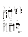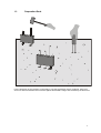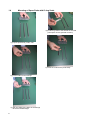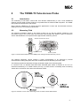
1
TRIME-FM
User Manual
Thank you for buying IMKO.
Should you have any queries please don’t hesitate to contact your local distributor or address directly
to:
IMKO Micromodultechnik GmbH
Im Stoeck 2
D-76275 Ettlingen
Germany
Phone:
+49-7246-5921-0
Fax:
+49-7246-90856
e-mail:
[email protected]
internet:
http://www.imko.de
th
as of April 15 , 2001
Table of contents
1
TRIME-FM2 /-FM3 Field Measurement Device (Version P2 or P3) _____________________ 3
1.1
Functional Description ______________________________________________________ 3
1.1.1
1.1.2
1.1.3
1.1.4
1.1.5
1.1.6
1.1.7
1.1.8
1.1.9
1.1.10
2
Manual Operation _________________________________________________________________________ 3
Probe Connection _________________________________________________________________________ 3
Basic Alignment___________________________________________________________________________ 3
Display Functions / Error Messages ___________________________________________________________ 3
Battery Operation _________________________________________________________________________ 4
Battery Charger ___________________________________________________________________________ 4
External Power Supply _____________________________________________________________________ 4
Data Logger Operation _____________________________________________________________________ 4
PC-Connection via RS232___________________________________________________________________ 4
Technical Data _________________________________________________________________________ 5
1.2
Probe Dimensions _________________________________________________________ 6
1.3
Preparation Rods __________________________________________________________ 7
1.4
Mounting of Spare Rods with O-ring Seals_______________________________________ 8
The TRIME-T3 Tube Access Probe ______________________________________________ 9
2.1
Introduction _______________________________________________________________ 9
2.2
Measuring Field ___________________________________________________________ 9
2.3
Measuring experiences_____________________________________________________ 10
2.4
Summary _______________________________________________________________ 11
3
Access Tubes and Augers ____________________________________________________ 12
4
Instructions for Access Tube Installation ________________________________________ 13
5
4.1
Fixing of the rubber bung ___________________________________________________ 13
4.2
Inserting T3 into the TECANAT tube __________________________________________ 14
Basic Alignment with the Calibration Set ________________________________________ 15
5.1
5.1.1
5.2
5.2.1
5.2.2
What is a basic alignment?__________________________________________________ 15
What are the benefits of the calibration set for the user? __________________________________________ 15
How to make the basic alignment?____________________________________________ 16
Preparation of the glass beads ______________________________________________________________ 16
Basic alignment procedure _________________________________________________________________ 16
6
EMV/EMI Precaution _________________________________________________________ 18
7
Instructions for Wiring _______________________________________________________ 19
7.1
8
2
Water tight connectors and cable confection for use with the environmental measurement
system ENVIS ___________________________________________________________ 20
Operating instructions ACS-series _____________________________________________ 21
1
TRIME-FM2 /-FM3 Field Measurement Device
(Version P2 or P3)
1.1
Functional Description
The TRIME-FM is a portable moisture measurement instrument, which has been developed for mobile
field use. It can additionally be supplied with an external power supply. It is connectable to a data
logger or a PC for automated data logging.
1.1.1
Manual Operation
The manual operation is very easy. Pressing the START-button switches on the TRIME-FM. Pressing
the button once again, starts the measurement. The message “Measuring...“ disappears after about 10
seconds and the measured values of the water content and the TDR level are displayed on the first two
lines. The TDR level can be used to assess the electrical conductivity of the soil or material. The
instrument switches off about three minutes after the last operation, in order to save battery power.
1.1.2
Probe Connection
There is a build-in non-volatile memory (EEPROM) inside the probe connector, where all calibration
data is stored, e. g. cable length, probe geometry, and calibration coefficients. Therefore several
probes can be used with the same TRIME-FM. It is possible to connect probes with different cable
lengths and different calibration data according to the device type P2 or P3. The device type P3 allows
only the usage of P3-probes and P2-probes can only be connected to P2-devices. Probes can only be
used at the TRIME-FM, which they were (basic) calibrated with. To prevent confusion, each probe has
a label with the serial number of the device, which it was calibrated with.
To screw the probe connector on is only necessary if the instrument is exposed to the weather. For
manual measurements with several probes, it is recommended not to screw on the coupling ring, in
order to be easy on the thread.
The insertion of the probes must be carried out very carefully in order to prevent air pockets around the
rods or the access tube, if the tube probe is used. Therefore the insertion of the rod probes with the
preparation rods is only recommended, if it is not possible to stick them in manually. Repeated
insertion in the same holes is not recommended, too. The access tubes should be inserted with our
auger equipment. Since the highest measuring sensitivity is directly around the rods or the access
tube, the TRIME-FM would measure too low values, if there was an air gap. In water saturated soils
the measured values would be too high.
The probe rods must be inserted in the soil completely, because the probe measures along the whole
length of the rods.
1.1.3
Basic Alignment
The basic alignment can be done without any connection to a PC and without the calibration program
SMCAL. The TRIME-FM is set to the calibration mode by plugging the calibration connector. Please
refer to the chapter “Basic alignment with the Calibration Set“.
A calibration for a specific material cannot be established by using the calibration connector.
1.1.4
Display Functions / Error Messages
The LC-display of the TRIME-FM has four lines with 20 characters each.
Almost all messages, which can be displayed, are changeable, that means they can be translated to
the desired language. The modification of the texts can be done by the program TRIMETXT.
Generally, the third line is used to display status and error messages. It indicates, whether measuring
is active or the battery is just being charged or discharged. Occurred errors are indicated with error
number and address.
Error numbers between 1 and 29 are internal errors, which are displayed without additional text.
3
Error No.
Error Text
Possible Cause of Error
30
TDR may be defective
TDR electronic or probe cable defective
31
TDR level not found
TDR level searching lasted too long, may occur with bad signal quality
due to conductive soil or material
32
Probe not connected
No probe connected or probe connector defective
33
Salinity too high
Electrical conductivity of soil/material too high
34
Invalid probe data
Data in probe connector not plausible or probe connector defective
35
Battery is empty
Supply voltage too low or battery empty
1.1.5
Battery Operation
The internal chargeable battery has a capacity of 600 mAh, which allows about 300 measurements.
This is only an approximate value and dependent on a lot of influences, like ambient temperature,
pauses between the measurements, measured material and age of the battery. The measuring
operation should be terminated, as soon as the error message “Battery is empty“ appears.
If the battery capacity is not sufficient or battery operation is not desired, at all, an external battery or
power supply may be connected via the RS232 connector.
Attention: Charging is only allowed with the supplied ACS charger!
1.1.6
Battery Charger
The micro controlled charging method of the ACS charger guarantees an optimised battery lifetime.
1. Regarding the battery lifetime the “discharging“ mode is most favourable. It is started by pressing
the yellow button. However, it is not harmful for the battery to use the “charging“ mode if the
charging shall be carried out fast, i. e. in up to 4 hours. The “discharging“ mode lasts between 6
and 7 hours.
The charger can remain connected as long as one likes. The battery can not be damaged by it.
Please refer to the charger operating instructions on page 21.
1.1.7
External Power Supply
An external power supply (9..15V/300mA) can be connected via the RS232-cable. In this case the
internal battery is disconnected and the instrument is supplied by the external power only. It doesn’t
switch off then, but remains on as along as the external voltage is connected. Therefore the data
logger operation requires an external power supply.
It is even possible to connect an external battery if the capacity of the internal battery is not sufficient.
1.1.8
Data Logger Operation
The TRIME-FM comes with an analogue output of 0..1V in order to make data logging with external
devices possible. For this data logger operation the TRIME-FM should measure automatically. The
cyclic measuring mode (mode C) can be set by the program TRIMESET, whereas the cycle time can
be chosen.
1.1.9
PC-Connection via RS232
The TRIME-FM can be connected to a PC via the RS232 connector and the appropriate cable, in order
to carry out data logging, changing the operating mode, or calibration. As long as the PC is connected
the power-off automatic is disabled to prevent switching off. It is to be considered that the internal
battery is discharged as long as the PC is connected.
4
1.1.10
Technical Data
Power supply:
Supply current:
7V..15V-DC, 600 mA/h battery capacity
8mA standby
200mA while 10..15sec. measuring time
0,1%
±0,3%
0-100%
-15°C...50°C, expanded temperature ranges on request!
max. ±0,5%
analogue output 0..1V or 0(4)..20mA, RS232/V24,
IMP232 MICRONET
calibrated for mineral soils,
but individually adaptable per software
weatherproof, robust aluminium die-cast (IP65)
Resolution:
Repeating accuracy:
Measurement range
Temperature range:
Temperature caused value drift:
Standard interface:
Calibration:
Case:
The measuring accuracy and -range as well as the tolerable range of bulk electrical conductivity
depends on the corresponding probe.
Connectable probes for TRIME-FM2
Coa x cable
Probe
P2G
Probe
P2Z
Probe
P2
Probe
P2D
Probe connector
Connector for
- analogue cable
- calibration plug
- battery charger
1:
2:
3:
4:
5:
6:
7:
Reserved
Reserved
Analog-Out 0..1V
Analog-Out-0V
SelfCal.
R/T (IMP-Bus)
COM (IMP-Bus)
4
5
6
Start
3
7
2
1
front view
Connectable probes for TRIME-FM3
3
4
Connector for
- external power supply
- RS232/V24
2
1
f ront vi ew
Probe
P3
Probe
P3Z
Probe
P3S
Tube Probe
T3
Pin 1: +U (9V..15V-DC)
max. 250mA
Pin 2: RxD
Pin 3: 0V
Pin 4: TxD
RS
232/V
24
Battery
charger
Power su
pp
ly
Pin
Pin
Pin
Pin
Pin
Pin
Pin
AC-banana plugs
external
battery
box
AC-Connector
5
Probe Dimensions
2-Rod
Probe
P2Z
2-Rod
Probe
P2G
63
2-Rod
Probe
P2
32
88
With screw
for optional
tube extension
20
50
80
100
80
30
65
15
Miniatur
Probe
P2D
40
1.2
160
14
Different length: 50, 80, 100mm
Rod diameter: 2,4mm
160
20
Rod diameter: 3,5mm
6
40
40
Rod diameter: 6mm
Rod diameter: 6mm
3-Rod
Probe P3
3-Rod
Probe
P3Z
63
3-Rod
Probe P3S
15
160
160
40
100
30
115
40
Triangular
arrangement
All pins can be replaced
6
20
20
Rod diameter: 3,5mm
8
35
35
for tube
extension
1.3
Preparation Rods
For the protection of the rod tips it is necessary to use the preparation rods for probe P2, P2Z, P2G
and P3. A defect and blank rod is sensitive against electrostatic charge and can destroy the electronic!
7
1.4
Mounting of Spare Rods with O-ring Seals
4) put silicon grease to the threads of the rods
(new spare rod are greased at works)
1) prepare probe body, seals, rods
5) screw the rods into the probe body
2) put the seals into the borings
3) push the seals to the basis of the borings
where the threads begin
8
2
The TRIME-T3 Tube Access Probe
2.1
Introduction
The measuring of soil water content with Time Domain Reflectometry is now a well established
method. However water content profiling is not possible with conventional TDR rod probes. The TRIME
tube probe was developed for this reason.
Since 1994 the TRIME-T3 has found numerous applications in earth and environmental sciences,
fulfilling even the most exacting requirements.
2.2
Measuring Field
The effective penetration depth of the probe is about 15 cm with the highest sensitivity in the
immediate vicinity of the access tube and decreases exponentially with distance. Figure 3 shows the
electric field distribution of the probe and the approximate measuring volume.
effective measurement volume
equipotential lines
aluminum plates
Figure 1: Electric field distribution of the TRIME probe and approximate measuring volume.
The elliptical measuring volume enables a higher representation to be achieved by several
measurements rotating the probe after each measurement and calculating the mean value.
The following experiment illustrates the high penetration depth of the measuring field:
In a bucket of 50 cm diameter filled with water saturated glass beads a moisture of 44 vol.-% is
measured. Measuring in a smaller bucket (see Fig. 3) would result in essentially lower measuring
values due to an amount of air within the measured volume.
Figure 2: Influence of a too small measuring volume on water content determination.
9
Note that the necessity of a close contact between access tube and material is vital for reliable
measurements and that the tubes should be installed by our recommended method.
• For example at an assumed water content of 15 vol. % an air gap of 1 mm around the whole length
of the tube would result in an underestimation of 1 - 2 vol. %.
• At a water content of 25 vol. % the error would be 5 vol.-%.
• At very high water contents (50 vol. %) errors may reach 10 vol. %.
• In the case of a water filled gap under conditions of saturation the gap error would be much smaller.
− Problems may arise, however, in very inhomogeneous soils and when drilling under very dry
conditions. For these soils other drilling methods are recommended (e. g. pre-boring with an
Edelman auger, washing mud into the cavity around the tube). Losses in accuracy must then be
accepted, and measurements immediately after installation are not recommended.
− Problems can also arise in swelling and shrinking soils, since cracks develop especially along the
access tubes.
2.3
Measuring experiences
The new TRIME technique was thoroughly tested in the field and compared both to neutron probe
measurements and thermo gravimetrically determined values.
Figure 3: Comparison of TRIME measurements and gravimetric water content determination for a clayey soil.
Figures 5 and 6 show a comparison of water content determinations for a loess and for a heavy clay,
made with a neutron probe (Wallingford), the TRIME-T3 probe, and the gravimetric method. In contrast
to the neutron probe, which is not suitable for measurements near the surface due to radiation losses
to the atmosphere, TRIME has no problem at all to measure directly at the soil surface.
10
Figure 4:
Figure 5 :
Comparison of neutron probe, TRIME-T3 and gravimetric method for water content
determinations in a loess soil.
Comparison of neutron probe and TRIME-T3 for water content determinations an illitic clay.
Some materials, especially very clayey soils and soils with high organic contents, can afford material
specific calibrations due to their different dielectric behaviour.
A limiting factor in TDR measuring is the bulk soil electrical conductivity. For the TRIME-T3 tube probe,
bulk soil electrical conductivity should not exceed 1 dS/m. Note that bulk soil electrical conductivity is a
combination of the pore water electrical conductivity and the surface conductivity of the soil matrix. Due
to the tortuous nature of the conductivity path in the soil (soil type dependent), the bulk soil conductivity
is much lower than the electrical conductivity of the pore water and it is dependent on water content.
2.4
Summary
The TRIME tube probe is a promising new tool for determining water content profiles with the TDR
method. Fast, routine and non destructive measurements of water content without the use of
hazardous radioactive materials are possible. A measuring accuracy of ± 2 vol.-% is possible, provided
that soil and access tube are in close contact and bulk soil electrical conductivity doesn’t exceed
1 dS/m.
11
3
Access Tubes and Augers
The penetration depth of the measurement field of the 44mm TRIME tube-access-probe is up to
150mm into the soil. The measurement sensitivity is the highest near the access tube and decreases
exponentially into the medium. Therefore the insertion method of the access tube is very important.
Ramming head
with clamp device
Auger
equipment for
the direct setting
of the access
tubes into
homogeneous
soils.
Screw
auger
with
handle
Small version
without soil
anchors for
access tubes
with 1m length
Pre-boring
with an
Edelmanauger
Fixing
of the
rubber
bung
TECANAT
access
tube
Support
pillar
with clamp
device
Soil
anchor
Internal
steel guide
and
protection
tube
Clamp
device
for
rubber
bung
Steel cutting shoe
of access tube
Pre-boring of bore holes with standard augers destroy the soil texture, because it is difficult to come to
a good and close contact of the access tube inside the soil. With the described auger equipment it is
possible to set the access tubes directly into homogenous soils without pre-boring. In very stony soils it
is not possible to use this method. Therefore it could be possible to use an Edelman-Auger for preboring and closing the air gaps with mud. Changes in soil structure, and a delay time (up to 4 weeks)
before it is possible to come to precise measurement values must then be accepted.
The IMKO auger equipment consists of: access tube support pillar with three soil anchors, ramming
head with clamp device, screw auger with handle, clamp device for the rubber bung, and an internal
steel guide/protection tube. Deliverable is a small version without soil anchors for setting of glass fibre
tubes with 1m length.
A steel cutting shoe is glued into the access tube. The screw auger, that moves easily within the guide
tube is used to drill out soil to about 0,1m below the cutting shoe. Depending on soil homogeneity, the
tube can be hammered 5..10cm into the soil. This cycle is repeated until the tube is fully installed. The
internal protection tube is then removed and the access tube can be sealed by a rubber bung.
12
4
Instructions for Access Tube Installation
The following instructions should be taken account of:
FixationScrew
The ramming head, the TECANAT
access tube and the internal steel guide
and protection tube are one unit.
Ramming Head
The internal protection tube has to lie on
with Clamp Device
the cutting shoe of the access tube,
before it can be fixed with a screw to the
ramming head. This fixation is
necessary to secure the shoe against
being squeezed out by the returning
force of the hammer-blow.
The access tube, however, is fixed to
Pull for best the ramming head by the clamp device.
position
Both fixation screw and clamp device
should be controlled during the
installation process and be re-adjusted
with the adjustable levers if necessary.
The screw auger, that moves easily
within the guide tube is used to drill out
soil to about 0,1m below the cutting
shoe. Depending on soil homogeneity,
the tube is then hammered 5-10 cm into
the soil with a plastic hammer (with open
support pillar clamps!). The guide tube is
not used for making the hole in the first
instance because this could result in soil
compaction around the hole, which
would lead to higher measurement
values.
The access tube support pillar with three
ground anchors avoids vibrations that
would cause air gaps. Then the clamp of
the support pillar must be closed and the
soil can be removed with the screw
auger. When the tube reach the support
pillar, it must be removed and the
access tube can be inserted to the final
depth without the support pillar.
4.1
Fixing of the rubber bung
The rubber bung can be pushed into the access tube with the screw- adapter and the handle (the
screw-adapter can be replaced instead of the screw auger) and can be fixed at the bottom of the
access tube with two turns of the handle. If pushing down the rubber bung turns out to be difficult, just
apply some talcum powder on the rubber bung sides and into the access tube.
A plastic collar should be mounted around the tube to prevent water from running down the tube wall
and a plastic cap to protect the tube against rain.
13
4.2
Inserting T3 into the TECANAT tube
When you are going to work with your TRIME-T3 tube access probe:
Press the spring mounted wave-guides to the probe body when you insert the T3 probe into the tube!
Thereby you avoid ripping off the spring mounted wave-guides.
art
Press
St
e
x ca bl
2
2
1
1
Press
C oa
TRIME-FM3 or TRIME-IPH
TECANAT plastic tube
Please note
Should you use new T3 probes (eight wave-guiding plates instead of two) in old GFK tubes, we advice
to carefully chamfer the inner top side of the GFK tube. Thereby you avoid ripping off the spring
mounted wave-guides.
Please note
With the T3 comes three aluminium rods, which can be screwed together. They can be used to
orientate the T3 probe in the borehole.
14
5
Basic Alignment with the Calibration Set
Coax ca ble
TRIME
Probe
Probe
connector
dry glass
beads
water
saturated
glass beads
Start
Calibration
Connector
5.1
What is a basic alignment?
The basic alignment serves to compensate the cable length and tolerances of the probe
mechanics (thickness of the rod coating, rod length, etc.). After two measurements, one in dry
and one in water saturated glass beads, the calibration data is calculated and stored in the
TRIME probe’s connector.
Every TRIME probe must be calibrated before it can supply proper measurement results. It is
very important that the probe is calibrated with the device it belongs to. This calibration is
regularly done by IMKO before the delivery of new probes.
Please note that probes can only be used with the TRIME device they were calibrated with!
5.1.1
What are the benefits of the calibration set for the user?
With the calibration set you can easily calibrate probes on your TRIME instrument by yourself.
The calibration set offers the following advantages to you:
1. If defective probe rods must be changed you are able to make the required basic
alignment by yourself.
2. You can calibrate probes purchased later with your TRIME-instrument by yourself.
3. If you have two or more instruments you can change the configuration of instruments
and probes anytime by a new calibration of the appropriate probes to the specific
instruments.
You would have to send instruments and probes to us in any of the above cases where basic
alignment is required if you have no calibration set. IMKO will charge calibration costs. Moreover
you will save the forwarding charges and you will not have to interrupt your measuring campaign,
if you calibrate by yourself.
However, the calibration set allows only to make a basic alignment of the TRIME probes. You
can not change the standard calibration for specific materials with it. For this purpose a
measurement data set must be created with this specific material. In order to calculate the
calibration data for this data set and to download it into the TRIME-probe you need the
calibration program SMCAL.
15
5.2
How to make the basic alignment?
5.2.1
Preparation of the glass beads
First, the glass beads, which are supplied with the calibration set, have to be prepared. The
preparation of the dry glass beads is uncritical: Fill up one of the containers until the rods of the
probe could completely be inserted. To achieve a constant density, knock the container several
times against the ground. After a long usage of the glass beads the density increases. Therefore
they should be poured out into another bucket and poured back to achieve the original density.
The preparation of the water saturated glass beads is more critical, because water dissolves
Na2O and K2O from glass. This causes a rising pH-value and an increased electrical
conductivity. This property is most intensive with new glass beads. Therefore the glass beads
should be washed intensively with tap water in a large container (e.g. 10 litre bucket). Fill a
bucket with water, stir the beads under water and then pour out the water. This procedure should
be done at least five times, each time with fresh water. If the glass beads have been in use for a
longer time, three times is enough.
Now the second calibration container has to be filled with water in order to be able to fill in the
glass beads without remaining air-bubbles. An additional precaution to remove air-bubbles is to
stir slightly while filling in the glass beads. The container must now be knocked against the
ground some times to achieve a constant density. The surplus water must be poured out until the
thickness of the water film above the glass beads is below 2mm.
The water saturated glass beads should be in a temperature range between 20°C and 25°.
Please note that the electrical conductivity of the water saturated glass beads medium
increases already after a few days storage. Therefore the glass beads must be washed again
before the next calibration.
5.2.2
Basic alignment procedure
The basic alignment can be done with both the calibration connector (only TRIME-FM) and the
calibration program SMCAL (please read the information about the basic alignment with SMCAL in the file
README.TXT in the subdirectory BASICCAL of the SMCAL-disk).
Only the procedure with the calibration connector is described in the following:
Before starting the essential calibration, connect the probe to the TRIME-FM and press the
START button to switch on the instrument. After this „dummy measurement“ is finished, you can
plug in the calibration connector at the side of the TRIME-FM. The display shows the first
reference value of dry glass beads for the appropriate probe (e.g. 2,8%). The probe cable must
now be unwound and spread out in a way that the cable doesn't touch itself. Moreover, it must
have a distance to metal objects (e.g. metal table-top) of at least 10cm. The probe must now be
stuck vertically into the dry glass beads. Both, container and TRIME instruments, shouldn't touch
metal objects, too! Now, knock laterally to the container to achieve that the glass beads fit
closely to the probe rods. Then start the first measurement by pressing the START button.
After the measurement is finished, the second reference value is displayed (e.g. 43,8%). The
probe has now to be stuck into the water-saturated glass beads. As described above please take
care that the cable is not in contact with metal objects and itself. The probe rods must be
completely and vertically inserted into the glass beads. The cable must not put force on the
probe. Knock slightly laterally to the container for a close fitting of the glass beads to the probe
rods. Now start the second measurement by pressing the START button.
After the measurement time has expired and the calibration is completed and the next probe can
be calibrated. If you want to terminate the calibration work, remove the calibration connector!
To check the calibration success, measure in dry and saturated glass beads and verify the
results with the reference values. The calibration would have to be repeated, if the deviations are
too great.
16
STEP LIST BASIC ALIGNMENT
1 Connect the probe (P3 etc.!) to the TRIME-FM.
2 Press START button for switching on the TRIME-FM. Display shows:
TRIME-System
Software Version 2.3
SN XXXX
(=serial number of the TRIME-FM)
3 Connect the calibration connector at the 7pin flange connector of the
TRIME-FM. Display shows:
BASIC CALIBRATION
1. dry glass beads
Reference 2.9Vol%
4 Put the P3 probe into your dry glass beads. (read “Preparation of the
glass beads”p.16)
5 Press START button for starting the measurement
Display shows 1st:
Display shows 2nd:
Display shows 3rd:
BASIC CALIBRATION
1. dry glass beads
Checking TDR Circuit
BASIC CALIBRATION
1. dry glass beads
Measuring.......
BASIC CALIBRATION
2. sat. glass beads
Reference 43.7Vol%
6 Put the P3 probe into your saturated glass beads (Read the description
of the TRIME-FM user manual too!)
7 Press START button for starting the measurement
Display shows 1st:
Display shows 2nd:
Display shows 3rd:
BASIC CALIBRATION
2. sat. glass beads
Checking TDR Circuit
BASIC CALIBRATION
2. sat. glass beads
Measuring.......
BASIC CALIBRATION
1. dry glass beads
Okay, next probe!
Reference 2.9Vol%
6 Probe is calibrated.
You can connect the next P3 probe for calibration (begin with step 1)
You finished calibration work? Then unplug the calibration connector!
17
6
EMV/EMI Precaution
EMV/EMI precaution by means of ferrite filters ensures better disturbance suppression. Ferrite filters
are clipped to both ends of the probe cable. They are important for an improved measurement
accuracy.
snap
here
EMV/EMIFerrit Filter
ZCAT-1518
TRIME-FM
Measuring
Start
EMV/EMIFerrit Filter
TRIME-FM
Analogcable
Vers ion P2
Gm b H
M I C RO M O D U LTE C HN I K
ZCAT-2035
RS232-cable
snap
here
snap
here
ZCAT-2035
rod probe
tube
probe
18
7
Instructions for Wiring
In diesem Bereich
einfetten !
Buchseneinsatz
female insert
Gewindering
coupling ring
In this area place
a thin coat of grease !
Hülse mit Feder
Shell with spring
Dichtring
gasket
Druckring
thrust coilar
Druckring
thrust coilar
Druckschraube
pressing screw
Dichtring
gasket
Dichtring
gasket
Druckschraube
pressing screw
An den schwarz markierten
Bereichen den Siliconkleber so
dick auftragen, daß Dichtring
und Kabel wasserdicht verklebt
sind.
Gewindering
coupling ring
O-Ring
At the black marked areas
apply silicon glue so thick
that the gasket and the
cable are sticked together
and are waterproofed.
19
7.1
Water tight connectors and cable confection for use with the
environmental measurement system ENVIS
Dear Customer,
water tightness of the sensor modules (IP65) and the connectors (IP67) can only be guaranteed by
observing the following:
Start
Gm bH
M ICR OM OD UL T E C HNIK
1. In case of carrying out the cabling of the distribution modules by yourself, please make sure
that the cable seals fit tightly. Only cables with a sheath diameter of 5 to 8mm should be used.
In case of smaller diameters water may enter the connector, the distribution box or the
measurement device and may alter measurements or even destroy the equipment. IMKO
supplies special seals.
2. All unused connectors have to be protected by blind covers. IMKO supplies all equipment
respectively all open connecting terminals protected by blind covers. Additional ones can be
obtained by IMKO.
3. When installing the connectors, special attention has to be paid to the connectors being
threaded with care. The threads have to be aligned correctly to ensure efficient tightness. In
addition, the connector should only be hand-screwed, i.e. without use of tools (e.g. pliers).
A thin coating of grease should be applied to the threads of the threaded ring and to the
connector socket in order to ensure easy removal even after long periods of use.
20
8
Operating instructions ACS-series
Use of the charger
Automatic charger / discharger for 4-10 cells nickel-cadmium and nickel-metalhydrid battery packs
(4,8-12,0 V) with a capacity of 500–5000 mAh (ACS 410p traveller 800-9.000 mAh).
Features
•
•
•
•
•
•
•
•
•
Micro controller controlled charging
Test phase at the beginning of the charging in order to recognize and indicate defect battery
packs
Short circuit detection and electronic protection against reversed battery
Battery condition at the beginning of the charging is of no importance for the battery packs
Supervision of the charging condition by a micro controller during the whole charging time
safety stages like voltage gradient supervision and -delta U switch off as well as a safety timer
are integrated
possibility of discharging of the battery packs before use by pressing the button; after that,
automatic switching over to the charging
automatic switching over to trickle charge
state indication through illuminated display
LEDs
Illuminated display red (1): the flashing of the red illuminated display can have different meanings:
1. it signs the perfect contact of the battery packs during the test phase (about 10 seconds).
2. it signs that the battery pack is not connected properly with regard to the pole
3. it signs the defect battery pack or unsuitable amount of cells
4. it signs the discharging after pressing the PRESS button
Permanent light signs the charging of the battery packs.
Illuminated display green (2): battery pack fully charged, trickle charge
Operating elements
Discharging button (3): the discharging is started by pressing the PRESS button (for about two
seconds).
Attention
Only charge rechargeable Ni-Cd / Ni-MH battery packs.
By using other batteries there is Danger of explosion!
Caution
Keep your charger in a dry place (indoor use only). The charger should be disconnected from the
mains when not in use. Do not plug in the charger in case of damaged cabinet or power plug
21
Operation
The charger starts charging automatically as soon as a battery pack is installed and the charger is
plugged in. Usually, the battery packs are brought into contact by the plugs which are enclosed the
supply. If the red LED after the test phase (about 10 seconds) still keeps flashing, check the polarity of
the battery pack. Please gather the changing of the polarity (+/-) of the battery pack out of illustration
No. 5. If the red LED is flashing again after the test phase and does not switch over to permanent light
for charging, either the battery pack is defect or the battery pack might also not have the right number
of cells (less than 4 cells (4,8V) or more than 10 cells (12,0 V)). The test phase is followed by the
charging procedure (red LED is permanent on). After the charging procedure, the charger switches
automatically over to trickle charge (green LED is flashing; red LED is off). The starting of the
discharging procedure occurs by pressing ( about 2 seconds) the button for discharging (3). However,
this discharging procedure should only take place after the test phase. After discharging, which can in
individual cases last for several hours, the charger automatically switches over to charging.
Use in motor vehicles and trucks ( only ACS 410 mobile)
The ACS 410 mobile can be plugged into a 12-32 V DC outlet. If you use it on DC you have to connect
the provided DC cable to the cigarette lighter.
Note!! In passenger cars (12-16 V DC) only 4 to 6 cells battery packs (4.8-7.2 V) can be charged. In
trucks (24-32 V DC) you can charge 4 to 10 cells battery packs (4.8-12 V).
Environmental reference
Rechargeable batteries are not to be disposed in domestic waste. Surrender used batteries to your
dealer or rather to the battery collecting point
22