1
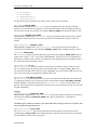
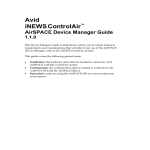
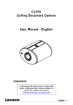
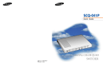
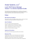
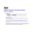
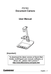
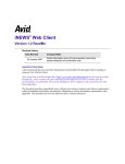
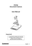
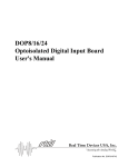
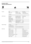
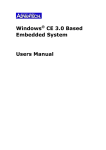
Avid Technology, Inc.
iNEWS ControlAir™
GVG Device Manager Guide
1.0.5
This Device Manager Guide is intended to advise you of certain technical requirements and
considerations that will affect your use of the GVG Device Manager with Avid’s iNEWS
ControlAir system.
It covers the following general areas:
•
Installation: the hardware and software needed to control a Grass Valley Group Profile PDR
or PVS series device with the ControlAir system
•
Configuration: the configuration options needed to control how the GVG Device Manager
and the Profile behave
•
Operations: notes on using the GVG Device Manager in a news production environment
2
GVG Device Manager Guide
Table of Contents
Installation .................................................................................................................................................... 3
Hardware.................................................................................................................................................. 3
GPI Remote Panel ................................................................................................................................ 3
Cabling ...................................................................................................................................................... 3
Tally Connection.................................................................................................................................. 4
Software Installation ............................................................................................................................... 4
Configuration ............................................................................................................................................... 8
Configuration File.................................................................................................................................... 8
[Configuration] ............................................................................................................................ 8
[Shows] ............................................................................................................................................. 11
[Channels] ...................................................................................................................................... 12
[GPIs]................................................................................................................................................ 14
[VideoServers]............................................................................................................................. 14
[WSStatusStrings] ..................................................................................................................... 14
Device Setup........................................................................................................................................... 16
Operations .................................................................................................................................................. 16
GPI Remote Panel for Playback ........................................................................................................... 16
Error Handling....................................................................................................................................... 18
Television Video Standards ..................................................................................................................... 22
Appendix .................................................................................................................................................... 23
Twelve Channels ................................................................................................................................... 23
Cabling ................................................................................................................................................ 23
[GPIs]................................................................................................................................................ 24
0130-05528-01
GVG Device Manager Guide
3
Installation
Hardware
In a typical setup, the GVG Device Manager (GVG DM) will run on the same computer as the
ControlAir Server program. It can also run on a separate computer if necessary. Therefore,
hardware requirements are identical to those used for the ControlAir Server. Refer to the iNEWS
ControlAir Installation and Operations Manual for further details.
The GVG DM connects to the Profile® via the network, unlike some other DMs that require serial
connections. Hence no additional cables to the Profile are needed for playout control.
One or more GPI Remote Panels can be used to control Profile playout as an alternative or an
addition to using the ControlAir Workstation. If you want to use remote panel control and you
installed GPI Remote Panel support when you installed ControlAir, then a digital I/O board is
also required.
Note: The GPI Remote Panels are designed for sequential playout of a list of clips. They do not support
taking clips out of order, as the Workstation does.
GPI Remote Panel
Avid Broadcast supports one or more GPI Remote Panels for the GVG DM. Each panel controls 2
channels on the DM. The GPI Remote Panels connect to a digital I/O board installed in the
computer that runs the GVG DM. The PCI-DIO24 board from Measurement Computing has been
qualified to work with ControlAir. The board ships with a CD containing drivers and an
installation program.
To install the board, perform the following steps.
1. Solder a 10-pin SIP 2.2 K pull-up resistor pack into the socket labeled Port A with the
common end in the spot marked HI on the board. The common end of the SIP is the end with
a “dot” or a “line” on it. This is usually on the left-hand side of the side with the writing.
2. Repeat Step 1 with Ports B and C.
3. Put the CD in the drive and install the installation program, called InstaCal.
4. Shut down the computer, install the card and reboot.
5. The “Add New Hardware” wizard will run and ask for a location; enter the drive letter of the
CD drive. The wizard will install the drivers.
6. Run the Instacal program and add the board as Board #1.
The cable that connects GPI Remote Panels to the digital I/O board is described in the “Cabling”
section.
Cabling
The cable layout between two GPI Remote Panels and the DIO24 card is shown below. For a full
12-channel setup using six 2-channel GPI Remote Panels, see the “Twelve Channels” section in
the appendix.
0130-05528-01
4
GVG Device Manager Guide
Panel 1
Channels A & B
DIO24 End
DB-37
Female Plug
A0
37
A1
36
A2
35
A3
34
G
19
GPI Panel End
DB-15
Female Plug
2
D0
7
D1
10
D2
14
D3
4
G
Panel 2
Channels C & D
DIO24 End
DB-37
Female Plug
A4
33
A5
32
A6
31
A7
30
G
17
GPI Panel End
DB-15
Female Plug
2
D0
7
D1
10
D2
14
D3
4
G
Tally Connection
Tally is connected through the DB-9 connector in the back of the GPI Remote Panel as follows:
Pin 1: 24V input for Channel A
Pin 2: 24V input for Channel B
Pin 5: Common (Ground)
Tally is active with +24V on Pin 1 or Pin 2, with respect to Pin 5. The Tally inputs on the DB-9
connector are opto-isolated and have no relation to the keyboard’s power or ground.
Pin1 and Pin2 inputs are connected to the anode of opto couples through 1500 ohm – 1/2 watt
resistors. A valid Tally event is a 24V signal (~10 mA) held on the opto coupler for at least 50ms,
and then OFF for 50ms. The Tally-controlled Auto-abort button “state” is checked before the
abort code is issued.
Software Installation
The Profile software is installed slightly differently for each of the Profile computers that Grass
Valley Group® produces. Refer to the table below for the list of versions on which the GVG DM
has been qualified.
Profile computer
PDR 200
PDR 400
PVS 1000
PVS 1100
GVG MAN
Qualified version
2.5.6.2
3.2.6.1
4.0.46.3
5.0.18.14
5.0.20.10
0130-05528-01
GVG Device Manager Guide
5
Before the GVG Device Manager can be installed, some of the Profile software must be installed.
Here are the steps for that installation.
1.
On the computer used for the GVG DM, install the Profile Software for computers that are not
Profiles. Refer to the Profile Software installation guide from Grass Valley Group for details.
2.
If you do not have EditStar installed on the Profiles to be controlled by the GVG DM, do the
following:
a.
On the Profiles to be controlled, install the GVG Profile or ProfileXP option of the
ControlAir Setup program, depending on the version of the Profile Software. Refer
to the ControlAir Installation and Operations Manual for details.
b. There are no more pre-installation steps. Proceed with the installation of the GVG
Device Manager.
3.
If you have EditStar 2.0 installed on the Profiles to be controlled by the GVG DM, you must
also install the EditStar Server Interface for ControlAir. Run the EditStar Server Setup
program.
The Welcome dialog box appears.
0130-05528-01
6
GVG Device Manager Guide
4.
Click Next. The IMPORTANT!!! dialog box appears. It contains hardware and software
requirements if you are installing the EditStar Server on a Profile.
5.
Since you are not installing the EditStar Server on a Profile, click Next. The Choose
Destination Location dialog box appears.
0130-05528-01
GVG Device Manager Guide
6.
Click Next to accept the default setting for the Destination Folder or click Browse to set
another drive and directory as the destination.
The Select EditStar Server Type dialog box appears.
7.
Select the EditStar Server Interface for ControlAir and click Next. The Select Components
dialog box appears.
0130-05528-01
7
8
8.
GVG Device Manager Guide
Click Next. The Setup Status dialog box appears, with a progress bar indicating the
percentage of the install completed. When the dialog box appears indicating the successful
completion of the install, click Finish.
Configuration
This section describes how to configure the GVG DM and the Grass Valley Group Profile.
Configuration File
All device manager configuration files are called Device Manager Profile (DMP) files, and have a
.dmp file extension. There are six sections to a GVG DM configuration file:
•
•
•
•
•
•
[Configuration]
[Shows]
[Channels]
[GPIs]
[VideoServers]
[WSStatusStrings]
Each section starts with its name in square brackets and contains lines of the form Keyword=Value.
The following sections describe each keyword available in each section, with a description
following it.
[Configuration]
The [Configuration] section contains general configuration for the GVG DM. There are four
required keywords:
0130-05528-01
GVG Device Manager Guide
9
• DeviceName
• SvrHostName
• NumberOfChannels
• LogFileDirectory
All other keywords are optional, with default values if they are not specified.
DeviceName=DEVICE_NAME
This keyword is required. The DeviceName keyword specifies the name that the GVG DM
reports to ControlAir Server. It appears in ControlAir Workstation and must match the name of
the video device used in production cues. Replace DEVICE_NAME with the iNEWS device name.
SvrHostName=SERVER_HOST_NAME
This keyword is required. The SvrHostName keyword specifies the host name of the computer
running the ControlAir Server. This is the server that the GVG DM will connect to when it is
started.
NumberOfChannels=CHANNEL_COUNT
This keyword is required. The NumberOfChannels keyword specifies the total number of
channels the GVG DM will control. Replace CHANNEL_COUNT with a number between 1 and 16.
FrameRate=FRAME_RATE
The FrameRate keyword specifies the frame rate of the Profile. Replace FRAME_RATE with one
of the words “NTSC,” “PAL,” and “NTSC_DROPFRAME.” If the keyword is not specified, the
DM will use a default value of NTSC. For details about the different television standards, refer to
the “Television Video Standards” section.
DisableAutoCue=Yes_No
The DisableAutoCue keyword specifies whether the GVG DM will auto-cue the next video
clip on a channel when the playing clip on that channel ends or is stopped. If Yes_No is set to
Yes, then the GVG DM will not auto-cue clips. If Yes_No is set to No, the GVG DM will auto-cue
clips. If the keyword is not specified, the default value is No.
AutoCueDelay=HOW_MANY_SECONDS
The AutoCueDelay keyword specifies how many seconds the GVG DM will wait after the end
of a playing clip before it auto-cues the next clip on that channel. Replace HOW_MANY_SECONDS
with the number of seconds it should wait. If DisableAutoCue is set to Yes, this keyword is
ignored. If the keyword is not specified, the default value is 0, which means that the next clip will
be cued immediately.
Logging
LogFileDirectory=DIRECTORY_NAME
This keyword is required. The LogFileDirectory keyword specifies the directory in which log
files are created. Replace DIRECTORY_NAME with a path to the directory. An example is
C:\GVGDMLogs.
CAUTION: If more than one instance of the GVG DM will be running on the same computer, they
must use different log file directories.
NumberOfLogFiles=FILE_COUNT
The NumberOfLogFiles keyword specifies the maximum number of log files that will be
created. Replace FILE_COUNT with a number between 1 and 999. If the keyword is not specified,
the GVG DM will create at most 10 log files.
0130-05528-01
10
GVG Device Manager Guide
StartLoggingOnProgramStart=Yes_No
The StartLoggingOnProgramStart keyword specifies whether the GVG DM should start
logging immediately upon starting up, or should wait until the user explicitly starts logging
using the Logging / Start Logging menu option. Replace Yes_No with Yes or No. The default is
to start logging immediately.
Diagnostic Messages
The following keywords determine which types of diagnostice messages the GVG DM reports,
and in which of two levels of specificity. The diagnostic message keywords come in pairs:
Reportmessagetype and ReportmessagetypeDetails, each taking a Yes or No. The first keyword
specifies that the GVG DM report general messages of the chosen type. The second keyword
specifies that the GVG DM report more detailed messages in addition to the general messages of
the chosen type. To specify Yes on a “details" keyword, you must also specify Yes on the
"general" keyword for that message type. If none of the keywords is specified, the defaults are:
ReportOnAirControl=Yes
ReportPlaylistManagement=Yes
ReportErrors=Yes
All others=No
ReportOnAirControl=Yes
ReportOnAirControlDetails=Yes
OnAirControl messages occur whenever a Play, Stop, Cue, Pause, or Channel Change command
is received from ControlAir Workstation.
ReportPlaylistManagement=Yes
ReportPlaylistManagementDetails=No
PlaylistManagement messages occur whenever an event or story is added to, deleted from, or
moved in the playlist.
ReportEventStatusChange=No
ReportEventStatusChangeDetails=No
EventStatusChange messages describe changes in the status of individual events.
ReportDeviceStatusChange=No
ReportDeviceStatusChangeDetails=No
DeviceStatusChange messages describe changes in the status of the Profile being controlled by the
device manager.
ReportErrors=Yes
ReportErrorDetails=No
Error messages describe situations where the device manager could not perform an action or a
status changed unpredictably.
Miscellaneous
CueReplacesPlayingEvent=Yes_No
The CueReplacesPlayingEvent keyword specifies whether the DM will stop any playing
event on a channel when the user makes a Cue request on that channel. If the keyword is set to
0130-05528-01
GVG Device Manager Guide
11
Yes, a Cue request will stop the currently playing event on that channel and cue the new event. If
the keyword is set to No, a Cue request will put the new event into Standby status until the
playing event ends, at which point the new event would be cued. If the keyword is not specified,
the default value is No.
ChannelPollInterval=HOW_MANY_SECONDS
The ChannelPollInterval keyword specifies how often the GVG DM checks to see if any
channels that are offline can be brought back online. If the keyword is not specified, the default is
10 seconds.
CanPlayTransferringMedia=Yes_No
The CanPlayTransferringMedia keyword specifies whether or not the DM should allow a
transferring clip to be played before the transfer completes. The default value is No, in which
case a transferring clip cannot be played until the clip is wholly available on the Profile. If you
specify Yes, the DM allows a transferring clip to be played after enough media has been
recorded. The amount depends on the video server, but is generally between 5 and 10 seconds.
SignalStartOfTransfer=Yes_No
SignalEndOfTransfer=Yes_No
SignalStartOfTransfer and SignalEndOfTransfer provide for signalling behavior only
if the CanPlayTransferringMedia key is set to Yes. SignalStartOfTransfer tells the DM
to send a message to ControlAir on detection of a clip that is transferring. This gives you
feedback that the clip is playable, but it may not be safe to do so.
SignalEndOfTransfer tells the DM to send a message to ControlAir on detection that a clip
transfer is finished. At this point, the clip is safe to play. The default value for both of these keys
is Yes; that is, messages will be sent to ControlAir at both the start and end of each transfer. The
messages will appear in the Error Log drop-down list in ControlAir Workstation and in the
Message bar in iNEWS Workstation.
DefaultDirectory= DEFAULT_VOLUME:DEFAULT_FOLDER
The DefaultDirectory keyword specifies the default directory from which Profile movies are
played.
• The DEFAULT_VOLUME is optional, and specifies the disk volume on the Profile
• The DEFAULT_FOLDER specifies the folder within a disk volume
The DEFAULT_VOLUME portion and the following colon are needed only when the Profile has
more than one disk volume.
Example:
DefaultDirectory=default
This would be the default directory on the first disk volume, such as “INT1:/default”.
EDLPrefix=EDL_PREFIX
The EDLPrefix keyword specifies the VideoID prefix for EditStar EDLs.
Example:
EDLPrefix=EDL=
This key word is required in order for the GVG DM to be able to play EditStar EDLs.
Note: You must also use the EditStar version of DVSObject.dll and the EditStar version of
Profile.exe or ProfileXP.exe.
[Shows]
The [Shows] section allows the system administrator to set up default directories on the Profile
for the clips in a particular show. Any show for which a default directory is desired is specified in
the [Shows] section with a line in the following format:
0130-05528-01
12
GVG Device Manager Guide
ShowINDEX=RUNDOWN_NAME:DEFAULT_VOLUME:DEFAULT_FOLDER
•
•
•
The RUNDOWN_NAME is the fully qualified path of the rundown queue in iNEWS
The DEFAULT_VOLUME is optional, and specifies the disk volume on the Profile
The DEFAULT_FOLDER specifies the folder within a disk volume
Note: The DEFAULT_VOLUME portion and the following colon are needed only when the Profile has more
than one disk volume.
Here are two examples and their effect on which clips are meant. Suppose that the [Shows]
section contains two lines:
Show1=SHOW.10PM.RUNDOWN:10p
Show2=SHOW.12PM.RUNDOWN:12n
Also suppose that the Profile contains one disk volume INT1 and four clips:
In the INT1:/10p directory, two clips named Fire and Barn
In the INT1:/12n directory, one clip named Fire
In the INT1:/9p directory, one clip named Fire
Then a user can refer to the various clips in the 10PM and 12PM shows as follows:
• The clips INT1:/10p/Fire and INT1:/10p/Barn can be entered as Fire and Barn,
respectively in the 10PM show
• The clip INT1:/12n/Fire can be entered as Fire in the 12PM show
• The clip INT1:/9p/Barn must be entered as 9p/Barn in either show
Additionally, the 10p clips can be entered as 10p/Fire and 10p/Barn into any show, and the GVG
DM will find them and play the right clip.
This section can also be left empty if the users always want to refer to clips by their full names.
The section must be present in the DMP file even if it is empty.
[Channels]
The [Channels] section maps each channel controlled by the GVG DM to a Profile channel. It
maps the channel index used by iNEWS to the channel and allows the user to specify a name that
is displayed in ControlAir Workstation.
A channel is specified by a line in the following format:
ChaniNEWS_Channel=Name:Video_Server:Channel_Name
•
•
iNEWS_Channel is a number (1, 2, 3...); this is the channel number used by iNEWS
Name is a string containing anything but a colon; this is the name of the channel
displayed in ControlAir Workstation
• Video_Server is the hostname of the Profile to be controlled
• Channel_Name is the name of the channel on that Profile that will be controlled
The setting of Channel_Name depends on both what Avid products are installed on the Profile
and what model of Profile is being controlled. There are three possibilities:
• The Profile is a PVS series computer and EditStar is not installed
• The Profile is a PDR series computer and EditStar is not installed
• The Profile is either a PDR or PVS series computer and EditStar is installed
EditStar is not currently qualified for the GVG MAN, so that is not a possible configuration. The
steps for each possibility appear below.
0130-05528-01
GVG Device Manager Guide
13
The Profile is a PVS series computer and EditStar is not installed
Channel_Name should be set to a number indicating the channel that is controlled by
ProfileXP.exe. To determine this number, look at the iNEWS Profile XP Server app running
on the Profile.
The channels that the GVG DM can control have names in the following format:
Video_Server.DVS.channelname
Set Channel_Name to be channelname.
The Profile is a PDR series computer and EditStar is not installed
Channel_Name should be set to a number indicating the channel that is controlled by
Profile.exe. To determine this number, look at the iNEWS Profile Server app running on the
Profile.
Note: The app appears virtually identical to the Profile XP Server app pictured above, with a different title.
The channels that the GVG DM can control are named
Video_Server.DVS.channelnumber
Set Channel_Name to be channelnumber.
The Profile is a PDR or PVS series computer and EditStar is installed
Channel_Name should be set to a number indicating the channel that is controlled by EditStar.
To determine this number, look at the EditStar Video Server app running on the Profile.
Note: The app appears virtually identical to the Profile XP Server app pictured above, with a different title.
The channels that the GVG DM can control have names in the following format:
Video_Server.DVS.channelnumber
Set Channel_Name to be channelnumber.
0130-05528-01
14
GVG Device Manager Guide
[GPIs]
For each channel, the [GPIs] section maps the buttons for that channel on a GPI Remote Panel
to the four actions (Play, Recue, Pause, Abort) available on that channel. For two GPI Remote
Panels, each channel and its associated action are specified by a line in the following format:
Button_Name=Button_Code:Button_Mask
•
•
•
Button_Name is made up of the action and the channel index; for instance, Play1 is the
Play action on Channel 1
Button_Code is the code for that particular button; all are specified in the Appendix
Button_Mask is the mask specifying which bits to inspect; all are specified in the
“Twelve Channels” section of the Appendix
The following is the setup for two GPI Remote Panels; see the “Twelve Channels” section for
configuration of up to six GPI Remote Panels.
Play1= 08:0F
Recue1= 04:0F
Freeze1=02:0F
Abort1= 01:0F
Play2= 07:0F
Recue2= 0B:0F
Freeze2=0D:0F
Abort2= 0E:0F
Play3= 80:F0
Recue3= 40:F0
Freeze3=20:F0
Abort3= 10:F0
Play4= 70:F0
Recue4= B0:F0
Freeze4=D0:F0
Abort4= E0:F0
[VideoServers]
The GVG DM can control multiple Profile simultaneously. The [VideoServers] section names
the Profile s being controlled and specifies which channels are on each Profile. Each Profile is
specified by a line in the following format:
ServerINDEX=NAME:ChanN1:ChanN2:...
•
•
•
INDEX is a number 1, 2, 3…
NAME is the name of the video server
N1, N2, ... are the numbers from the [Channels] section that indicate the channels on
that machine
Examples:
Server1=PDR001:Chan1:Chan2
Server2=PDR002:Chan3:Chan4
[WSStatusStrings]
Any or all of the event status strings displayed on the ControlAir Workstation can be changed in
this section. For any status not entered in this section, the default value will be displayed on the
0130-05528-01
GVG Device Manager Guide
15
ControlAir Workstation. This feature is provided to enable a site to customize the ControlAir
Workstation display. The new status text should be short enough to fit into the Status field on
the ControlAir Workstation.
Note: Changing the text of a status string does not change the meaning of the status.
The format for changing event status string text is:
Event-Status=status-description-string
Event-Status is one of the ControlAir status tokens defined below and status-description-string
is any text string. The statuses used by the GVG DM and their default values are:
The EVENT_UNKNOWN status is the initial state of every event. It indicates that the event
has not yet been processed by the GVG DM. The event cannot be cued or played in this
state. The default value is "Unknown".
The EVENT_UNAVAILABLE status indicates that the GVG DM could not find the event on
the selected video server channel. The event cannot be cued or played in this state. The
default value is "Unavailable".
The EVENT_INCOMPLETE status indicates that the event is being created on the video
server. The GVG DM can play the event before creation process is completed.
The EVENT_AVAILABLE status indicates that the event has been successfully processed
by the GVG DM. The event is ready to be cued or played. The default value is "” (an
empty string).
The EVENT_PENDINGCUE status indicates that the GVG DM is in the process of cueing
the event. The default value is "?Cued?".
The EVENT_CUED status indicates that the GVG DM has successfully cued the event and
it is ready for immediate play. The default value is ""Cued".
The EVENT_PENDINGPLAY status indicates that the GVG DM is in the process of taking
the event to air. This status is set by the ControlAir Workstation when the operator
presses the PLAY key. If an event remains in this state for more than a fraction of a
second, it indicates that the GVG DM was unable to air the event. The default value is
""?Play?".
The EVENT_PLAYING status indicates that the GVG DM has successfully taken the event
to the air channel. The default value is ""Play".
The EVENT_PAUSED status indicates the event was playing and the GVG DM
successfully paused the event on the air channel.
AccessDisplayGrouping=NUMBER PER GROUPING
This configuration option tells the ControlAir Workstation how to group the inventory blocks,
which appear in the Inventory column. For instance, if it is set to 2, the line in the configuration
file would appear as follows: AccessDisplayGrouping=2
0130-05528-01
16
GVG Device Manager Guide
If set to 2, there will be a space between successive pairs of inventory blocks at the ControlAir
Workstation, as shown below:
For more information on inventory blocks, see Chapter 4 of Avid’s iNEWS ControlAir User
Manual.
Device Setup
The Profile must be running either iNEWS Profile.exe or iNEWS ProfileXP.exe for the
GVG DM to connect to it. These programs are installed by the “GVG Profile or ProfileXP” option
of the ControlAir installer; see the “Installing ControlAir Software” section of the iNEWS
ControlAir 1.0.5 Installations/Operations Manual for details.
To set up the Profile to connect to the GVG DM, perform the action below that corresponds to the
Profile to be controlled.
• If the Profile is a PDR series computer, start Profile.exe.
• If the Profile is a PVS series computer, start ProfileXP.exe.
Operations
The GVG DM can be controlled from ControlAir Workstation in the same way that all other
device managers are controlled. Refer to the iNEWS ControlAir 1.0.5 User Manual for more details.
The GVG DM also supports sequential playback via GPI input. The following section describes
the two GPI Remote Panels and their behavior.
GPI Remote Panel for Playback
Figure 1 – A 2-channel GPI Remote Panel
0130-05528-01
GVG Device Manager Guide
17
The GPI Remote Panel has 10 buttons on the front. The first button on the left is an Enable for the
Tally-controlled Auto-abort feature for Channel A, and the last button on the right is the Tallycontrolled Auto-abort feature for Channel B. Auto-abort is enabled if the button is depressed. If a
second Control panel is used, Channels C and D would have the same setup as Channels A and
B, respectively.
Each set of four buttons controls a single channel. The left set controls Channel A and the right
set controls Channel B. The buttons perform the Play, Recue, Freeze, and Abort actions,
respectively. These are very similar to the Play, Cue, Pause and Stop keys available on the
ControlAir Workstation. However, they have slightly different behaviors.
•
The Play button starts playing the next clip known to the DM on the specified channel.
This is the next clip assigned to the channel after the last played clip. Because it is
designed for sequential play, it does not play the event under the cursor as the
Workstation Play key does.
•
The Recue button stops the current playing clip on the specified channel and recues it for
Play again. If there is no playing clip, this button does nothing. This is different from the
Workstation Cue key, which merely cues the clip under the cursor. The Recue button is
not affected by the CueReplacesPlayingEvent keyword, while the Workstation Cue key is
affected by it.
•
The Freeze button pauses the currently playing clip on the specified channel. If there is
no playing clip, this button does nothing. To start the clip rolling again from its paused
position, you must press the Play button. This is different from the Workstation Pause
key, which works as a toggle; pressing the Pause key again will start the clip rolling
again, as will the Play key.
•
The Abort button stops the currently playing clip on the specified channel. If there is no
playing clip, this button does nothing. This is different from the Workstation Stop key,
which can also uncue a manually cued clip to let the DM auto-cue a clip.
The typical workflow for GPI Remote Panel control is to press the Play button to start a clip, then
either let it run out or press the Abort key to stop it. If the operator wants to preview a clip, she
would press the Play button followed by the Recue button. If the operator wants to skip the
currently cued clip, she would press the Play button followed quickly by the Abort button to
advance to the next event.
The Play, Recue, Freeze, and Abort buttons are always lit. They are controlled by the panel’s
microprocessor. The two Tally-controlled Auto-abort buttons are mechanically latching switches,
and the LEDs for these keys are controlled by the microprocessor. If the Tally-controlled Autoabort button is out, the LED will be OFF, indicating auto-abort is not enabled. If the Tallycontrolled Auto-abort button is in, the LED will be ON, indicating auto-abort is enabled.
Note: An output code is not sent when simply toggling the Tally-controlled Auto-abort button. Only the
panel is aware of the button’s state, and the LED displays the correct status. A valid tally event (if enabled)
is reported exactly the same as a valid keypress. No output code is sent if a valid tally event is detected
when the Tally-controlled Auto-abort button is OFF.
When you press any Play, Recue, Freeze, or Abort key, the Tally-controlled Auto-abort LED
switches to its reverse state for 1/4 second to indicate a valid key-press. If the Tally-controlled
Auto-abort button’s LED does not toggle, a valid key-press was not detected and an output code
will not be sent. If you press a key and the enable light toggles for 1 second, an invalid key
0130-05528-01
18
GVG Device Manager Guide
combination was detected and code was not sent. Two keys pressed at the same time for a single
channel is invalid.
Error Handling
This section lists the GVG DM error messages in alphabetical order. Each error message is
followed by its location, a category, a description of the problem and, if appropriate, steps to take
to resolve it.
The possible categories are:
• Configuration errors - setting up the DMP file correctly
• Run-time errors
Words in italics in the error message descriptions below describe the use of the actual value that
appears in the actual error message. For example, a screen message “Cue of event ‘Fire’ failed on
channel ‘A’ ” matches the error description “Cue of event ‘eventname’ failed on channel
‘channelname’.”
Error: <<<Received Msg -- Message Type = value - NOT TRAPPED
Location: DM log file or screen
Category: Run-time
Action: The DM received a message from ControlAir Server that it cannot handle. It will ignore it
and continue processing. If this happens frequently, it is likely that there is data being lost
between the ControlAir Server and the DM.
Error: Can't establish connection to any channel. Good Bye!
Location: DM log file or screen
Category: Configuration
Action: The DM cannot connect to any specified channel. Check the DMP file and the Profile
configuration to ensure everything is correctly configured.
Error: Can't establish connection to the server. Good Bye!
Location: DM log file or screen
Category: Configuration
Action: The DM cannot connect to the ControlAir Server. Check that the correct host name is
specified in the DMP file and that the ControlAir Server is running. Then restart the DM.
Error: Can't Initialize GPI board: number for Control Panel
Location: DM log file or screen
Category: Configuration
Action: The DM cannot connect to the GPI board used for the GPI Remote Panels. Check that the
board is correctly installed and calibrated (using the Instacal program). Then restart the DM.
Error: Cue of event ‘eventname’ failed on channel ‘channelname’
Location: DM log file or screen
Category: Run-time
Action: A clip named eventname that the user tried to cue could not be cued. Check the Profile to
verify that it is in a state that allows cueing by a remote application.
0130-05528-01
GVG Device Manager Guide
19
Error: DEVICE: Channel name is back online
Location: DM log file or screen
Category: Run-time
Action: The channel named name was offline but has been brought back online. No further action
is required from the user.
Error: ERROR: At least one thread used for channel control failed to start
Location: DM log file or screen
Category: Run-time
Action: The DM could not start all the threads it needs to control the Profile. This is an
engineering issue; contact customer service.
Error: ERROR: Channel #channelname is not assigned to any video server in the [VideoServers]
section of the profile file.
Location: DM log file or screen
Category: Configuration
Action: Every channel must be assigned to some video server. Modify the DMP file to ensure that
each channel in the [Channels] section also appears in the [VideoServers] section.
Error: Error Connecting to Channel :channelname
Location: DM log file or screen
Category: Configuration
Action: The DM could not connect to the specified channel. Check the DMP file and the Profile to
ensure everything is correctly configured.
Error: Error getting duration from device
Location: DM log file or screen
Category: Run-time
Action: The DM could not determine a clip’s duration. Check the Profile to ensure that the DM is
connected and the Profile is in a correct state.
Error: Error getting position
Location: DM log file or screen
Category: Run-time
Action: The DM could not determine the amount of time remaining on a playing clip. Check the
Profile to ensure that the DM is connected and the Profile is in a correct state.
Error: ERROR: Invalid channel 'ChanX' specified on line '<line>' of the [VideoServers] section of
the profile file. There are only Y channels.
Location: DM log file or screen
Category: Configuration
Action: The channel number X must be between 1 and Y, inclusive. Modify the DMP file to
ensure that each channel in the [VideoServers] section appears in the [Channels] section.
Error: ERROR: Line 'line' in the [VideoServers] section of the profile file contains no video server
name.
Location: DM log file or screen
Category: Configuration
Action: Modify the DMP file to ensure that each line in the [VideoServers] section contains a
video servername.
0130-05528-01
20
GVG Device Manager Guide
Error: ERROR: Line 'line' in the [VideoServers] section of the profile file has a bad channel
specification: channelspec (should be of the form "ChanX").
Location: DM log file or screen
Category: Configuration
Action: A channel is specified by a string of the form "ChanX", where X is a number. Modify the
DMP file to ensure that each channel in the [VideoServers] section appears in the
[Channels] section.
Error: ERROR: Line 'line' in the [VideoServers] section of the profile file has no channels
specified.
Location: DM log file or screen
Category: Configuration
Action: Modify the DMP file to ensure that at least one channel is specified for each video server.
Error: Error reading Configuration section of profile file
Location: DM log file or screen
Category: Configuration
Action: The DM could not read the [Configuration] section of the DMP file. Modify the DMP
file to ensure that the syntax is correct.
Error: Error reading VideoServers section of profile file
Location: DM log file or screen
Category: Configuration
Action: The DM could not read the [VideoServers] section of the DMP file. Modify the DMP
file to ensure that the syntax is correct.
Error: ERROR: The profile file does not contain a [VideoServers] section.
Location: DM log file or screen
Category: Configuration
Action: Modify the DMP file to ensure that is contains a [VideoServers] section.
Error: Event failed to play.
Location: DM log file or screen
Category: Run-time
Action: The DM was unable to play an event the user tried to play. Check the Profile to verify
that it is in a state that allows playing by a remote application.
Error: EVT_STATUS: The clip 'clipname' on the video server 'servername' is now safe to play.
Location: DM log file or screen
Category: Run-time
Action: The DM has detected that a clip that was transferring to the video server has finished
transferring. The user need not take any action.
Error: EVT_STATUS: The clip 'clipname' on the video server 'servername' may not be safe to play.
Location: DM log file or screen
Category: Run-time
Action: The DM has detected that the clip is transferring to the video server and is not
completely present. Playing it may yield unpredictable results. The user need not take any
action.
0130-05528-01
GVG Device Manager Guide
21
Error: Invalid channel assignment.
Location: DM log file or screen
Category: Run-time
Action: The DM received a Play command for an event with a bad channel assignment. Correct
the channel assignment (either in ControlAir Workstation or in iNEWS) and try again.
Error: Missing channel configuration. Check profile...
Location: DM log file or screen
Category: Configuration
Action: The [Channels] section of the DMP file is missing. Modify the DMP file to ensure that
it contains a [Channels] section.
Error: Missing ControlAir host name. Check profile...
Location: DM log file or screen
Category: Configuration
Action: The [Configuration] section of the DMP file does not specify the computer running
the ControlAir Server software. Add the line “SvrHostName=hostname” to the
[Configuration] section of the DMP file, where hostname is the name of the computer
running the ControlAir Server software.
Error: Missing device name. Check profile...
Location: DM log file or screen
Category: Configuration
Action: The [Configuration] section of the DMP file does not specify the device name. Add
the line “DeviceName=devicename” to the [Configuration] section of the DMP file, where
devicename is the desired name for the DM.
Error: Missing number of channels. Check profile...
Location: DM log file or screen
Category: Configuration
Action: The DMP file does not specify how many channels the device has. Add the line
“NumberOfChannels=numberofchannels” to the [Configuration] section of the DMP file,
where numberofchannels is a number.
Error: The detail diagnostic keyword ‘ReportmessagetypeDetails’ cannot be set to Yes unless the
general diagnostic keyword ‘Reportmessagetype’ is also set to Yes.
Location: DM log file or screen
Category: Configuration
Action: In order to have details on a message type reported, the user must tell the program to
report the message type, as well as its details. Add the line “Reportmessagetype=Yes” to the DMP
file. If the line already exists, make the value after the equal sign equal to Yes.
Error: The profile file must specify a log file directory using the LogFileDirectory keyword.
Location: DM log file or screen
Category: Configuration
Action: Add the line “LogFileDirectory=directory” to the [Configuration] section of the DMP
file, where directory is a path where the log files will be stored.
0130-05528-01
22
GVG Device Manager Guide
Television Video Standards
The values available for the keyword FrameRate in the DMP file (see the FrameRate description
in the “Configuration File” section) are based on the television and video standards required for a
specific geographic location. The standards deal with frame refresh rates per second. Choices for
ControlAir are based on the following standards:
• NTSC
• PAL
NTSC is an abbreviation for the National Television Standards Committee. The NTSC committee
is responsible for setting television and video standards in the United States. The NTSC standard
for television defines a composite video signal with a refresh rate of 60 half-frames (interlaced)
per second. Each frame contains 525 lines and can contain 16 million different colors.
The NTSC standard is incompatible with most computer video standards, which generally use
RGB video signals. Special video adapters can be inserted into your computer that convert NTSC
signals into computer video signals and vice versa.
NTSC countries are: USA, Antigua, Bahamas, Barbados, Belize, Bermuda, Bolivia, Burma,
Canada, Chile, Colombia, Costa Rica, Cuba, Dominican Republic, Ecuador, El Salvador,
Greenland, Guam, Guatemala, Guyana, Honduras, Jamaica, Japan, South Korea, Mexico,
Netherlands Antilles, Nicaragua, Panama, Peru, Philippines, Puerto Rico, St. Vincent & the
Grenadines, St. Kitts, Saipan, Samoa, Surinam, Taiwan, Tobago, Trinidad, Venezuela, and the
Virgin Islands.
PAL is an abbreviation for Phase Alternating Line, the dominant television standard in Europe.
PAL delivers 625 lines at 50 half-frames per second. Many video adapters that enable computer
monitors to be used as television screens support both NTSC and PAL signals.
PAL countries include: Afghanistan, Algeria, Argentina (PAL-N), Australia, Austria, Bahrain,
Bangladesh, Belgium, Brunei, Cameroon, Canary Islands, China, Cyprus, Denmark, Finland,
Germany, Ghana, Gibralter, Greece (also SECAM), Hong Kong, Iceland, India, Indonesia, Ireland,
Israel, Italy, Jordan, Kenya, North Korea, Kuwait, Liberia, Luxembourg (also SECAM), Madeira,
New Zealand, Nigeria, Norway, Oman, Pakistan, Paraguay (PAL-N), Portugal, Qatar, Saudi
Arabia (also SECAM), Siera Leone, Singapore, South Africa, Spain, Sri Lanka, Sudan, Swaziland,
Tanzania, Thailand, Turkey, Uganda, United Arab Emirates, United Kingdom, Uruguay (PALN), Yeman (the former Yeman Arab Republic was PAL, and the former People's Democratic
Republic of Yeman was NTSC), Yugoslavia, Zambia, and Zimbabwe.
0130-05528-01
GVG Device Manager Guide
23
Appendix
Twelve Channels
This appendix describes the cabling requirement for controlling a GVG DM with up to 12
channels. For fewer channels, use fewer Panels. For example, to control six channels, you must
use three GPI Remote Panels.
Cabling
Panel 4
Channels
G&H
Panel 1
Channels
A&B
DIO24 End
DB-37
Female Plug
A0
37
Wire Color
GPI Panel
End
DB-15
Female Plug
2
D0
DIO24 End
DB-37
Female Plug
B4
6
Wire Color
GPI Panel
End
DB-15
Female Plug
2
D0
A1
36
Pink
Brown
7
D1
B5
5
7
D1
A2
35
Purple
10
D2
B6
4
10
D2
A3
34
Yellow
14
D3
B7
3
14
D3
G
19
Black
4
G
G
13
4
G
Panel 5
Channels
I&J
Panel 2
Channels
C&D
DIO24 End
DB-37
Female Plug
A4
33
Wire Color
Red
GPI Panel
End
DB-15
Female Plug
2
D0
A5
32
White
7
D1
A6
31
Blue
10
D2
A7
30
Orange
14
D3
G
17
Green
4
G
DIO24 End
DB-37
Female Plug
C0
29
C1
28
7
D1
C2
27
10
D2
C3
26
14
D3
G
11
4
G
Panel 6
Channels
K&L
Panel 3
Channels
E&F
DIO24 End
DB-37
Female Plug
B0
10
Wire Color
Wire Color
GPI Panel
End
DB-15
Female Plug
2
D0
GPI Panel
End
DB-15
Female Plug
2
D0
DIO24 End
DB-37
Female Plug
C4
25
Wire Color
GPI Panel
End
DB-15
Female Plug
2
D0
B1
9
7
D1
C5
24
7
D1
B2
8
10
D2
C6
23
10
D2
B3
7
14
D3
C7
22
14
D3
G
15
4
G
G
21
4
G
0130-05528-01
[GPIs]
Play1= 08:0F
Recue1= 04:0F
Freeze1=02:0F
Abort1= 01:0F
Play7= 8000:F000
Recue7= 4000:F000
Freeze7=2000:F000
Abort7= 1000:F000
Play2= 07:0F
Recue2= 0B:0F
Freeze2=0D:0F
Abort2= 0E:0F
Play8= 7000:F000
Recue8= B000:F000
Freeze8=D000:F000
Abort8= E000:F000
Play3= 80:F0
Recue3= 40:F0
Freeze3=20:F0
Abort3= 10:F0
Play9= 080000:0F0000
Recue9= 040000:0F0000
Freeze9=020000:0F0000
Abort9= 010000:0F0000
Play4= 70:F0
Recue4= B0:F0
Freeze4=D0:F0
Abort4= E0:F0
Play10= 070000:0F0000
Recue10= 0B0000:0F0000
Freeze10=0D0000:0F0000
Abort10= 0E0000:0F0000
Play5= 0800:0F00
Recue5= 0400:0F00
Freeze5=0200:0F00
Abort5= 0100:0F00
Play11= 800000:F00000
Recue11= 400000:F00000
Freeze11=200000:F00000
Abort11= 100000:F00000
Play6= 0700:0F00
Recue6= 0B00:0F00
Freeze6=0D00:0F00
Abort6= 0E00:0F00
Play12= 700000:F00000
Recue12= B00000:F00000
Freeze12=D00000:F00000
Abort12= E00000:F00000
GVG Device Manager Guide
25
Copyright and Disclaimer
This manual is copyright 2002, Avid Technology, Inc. All rights reserved. All Avid products are covered by U.S. and foreign patents, issued
and pending. Information in this publication supersedes that in all previously published material. Specifications and price change privileges
reserved.
The software described in this document is furnished under a license agreement and is protected under the copyright laws of the United
States and other countries.
U.S. GOVERNMENT USERS RESTRICTED RIGHTS: Use, duplication, or disclosure by the U.S. Government is subject to restriction as
set forth in subparagraph (b)(2) of the Technical Data and Computer Software-Commercial items clause at DFARS 252.211-7015, or in
subparagraph (c)(2) of the Commercial Computer Software-Restricted Rights clause at FAR 52.227-19, as applicable.
Avid is a registered trademark of Avid Technology, Inc. Media Browse, ControlAir, iNEWS ControlAir and iNEWS are trademarks of iNews,
LLC. Microsoft, the Microsoft logo, MS, MS-DOS, Win 32, Windows, Windows NT, Windows 2000, Windows NT Server, and the Windows
operating system logo are registered trademarks of Microsoft Corporation in the United States of America and other countries. UNIX is a
registered trademark of X/Open Company, Ltd. All other trademarks and registered trademarks used herein are the property of their
respective owners.
Avid
6400 Enterprise Lane
Madison, Wisconsin 53719 USA
Tel: +1-608-274-8686 Fax: +1-608-273-5876
Avid
Intec 1
Wade Road
Basingstoke Hants RG24 8NE UK
Tel: +44 1256 814300 Fax: +44 1256 814700
Avid
Unit 6
2 Eden Park Drive
North Ryde NSW 2113 AUSTRALIA
Tel: +61 2 8877 6880 Fax: +61 2 8877 6881
Avid
Tegel Forum
Breitenbachstraße 10
Berlin 13509 GERMANY
Tel: +49 30 5900993 0 Fax: +49 30 5900993 24
August 15, 2002
0130-05528-01
Printed in the United States of America
0130-05528-01