1
MaxIm DL
CCD Imaging Software
Version 4
Copyright © 1997-2004 Diffraction Limited
All rights reserved. This manual may not be copied, reproduced, translated, or converted to any machine-readable
form without the prior written approval of Diffraction Limited.
MaxIm DL User Manual
MaxIm DL™ LICENSE AGREEMENT
IMPORTANT: This agreement (the Agreement) is a legal agreement between you and Diffraction Limited
for this software product, including the software and associated media and printed documentation (the
Product). By installing, copying, or otherwise using the Product, you agree to be bound by the terms of this
Agreement. If you do not agree to be bound by the terms of this Agreement, immediately return the unused
Product to the vendor for a refund.
PRODUCT LICENSE
This Product is licensed, not sold. The Product is the property of Diffraction Limited or its licensers and is
protected by copyright law. This Agreement grants you the following rights:
1. You may install and use one copy of the Product on a single computer;
2. You may make one copy of the Product for archival purposes;
3. You may use the Product on a network provided that you have a licensed copy of the Product for each
computer that can access the Product over that network;
4. You may permanently transfer the Product and all of your rights under this license on a permanent basis
to another person or entity, provided that you retain no copies of the Product, that you transfer all of the
product including any components, updates, media, and manuals, that you provide Diffraction Limited with
the name, company, and address of the person to whom you are transferring the rights granted herein, and
the recipient agrees in writing to all terms of this Agreement. Please note that technical support and
upgrades are available only to the original customer.
You may not:
1. Sublicense, share, rent or lease all or any portion of the Product;
2. Reverse engineer, decompile, disassemble, modify, translate, or create derivative works from the
Product;
3. Use a previous version of the Product if you have received a replacement disk set or upgrade version as a
replacement for the previous version.
TERMINATION
If you fail to comply with the terms of this Agreement, Diffraction Limited may terminate the Agreement at
its discretion. Upon termination, you must return or destroy all copies of the Product including all of its
component parts. This does not restrict the rights of Diffraction Limited to other remedies.
JURISDICTION
This Agreement is governed by the laws of the Province of Ontario, Canada. Each of the parties hereto
irrevocably agrees to the jurisdiction of the courts of the Province of Ontario.
LIMITED WARRANTY
Diffraction Limited warranties that the media upon which the Product is distributed will be free of defects
for a period of thirty (30) days from the date the Product is delivered to you. In the event of a breach of this
warranty Diffraction Limited will, at the discretion of Diffraction Limited, either replace the defective
media or accept the return of the Product accompanied by proof of purchase for a refund. Diffraction
ii
License and Copyright
Limited does not warrant that the software in this Product will be defect-free or meet your requirements.
THIS WARRANTY IS EXCLUSIVE AND IN LIEU OF ALL OTHER WARRANTIES, WHETHER
EXPRESS OR IMPLIED, INCLUDING THE IMPLIED WARRANTIES OF MERCHANTABILITY,
FITNESS FOR A PARTICULAR USE, AND NON-INFRINGEMENT. This warranty gives you specific
rights. You may have other rights that vary from jurisdiction to jurisdiction.
DISCLAIMER
IN NO EVENT SHALL DIFFRACTION LIMITED BE LIABLE TO YOU FOR ANY SPECIAL,
CONSEQUENTIAL, INDIRECT, OR SIMILAR DAMAGES, INCLUDING ANY LOST PROFITS OR
LOST DATA ARISING OUT OF THE USE OR INABILITY TO USE THIS PRODUCT EVEN IF
DIFFRACTION LIMITED HAS BEEN ADVISED OF THE POSSIBILITY OF SUCH DAMAGES. SOME
JURISDICTIONS DO NOT ALLOW THE LIMITATION OR EXCLUSION OF LIABILITY FOR
INCIDENTAL OR CONSEQUENTIAL DAMAGES SO THE ABOVE LIMITATION MAY NOT APPLY
TO YOU. IN NO CASE SHALL DIFFRACTION LIMITED'S LIABILITY EXCEED THE PURCHASE
PRICE FOR THE PRODUCT.
MISCELLANEOUS
Should you wish to contact Diffraction Limited, you may do so at 100 Craig Henry Drive, Unit 106, Ottawa,
Ontario, K2G 5W3, Canada; telephone (613) 225-2732, fax (613) 225-9688. http://www.cyanogen.com
CREDITS AND COPYRIGHT
MaxIm DL and MaxIm DL/CCD are copyright © 1997-2004 Diffraction Limited. All rights reserved.
Developed by Doug George, Garland Sharratt, Eric Benson, Hilderic Browne, Chris Creery, Paul Boltwood,
Pat Browne, RoseAnne Mussar, and John Waring.
We would like to give a special thanks to Ray Gralak for contributing his Standard Deviation Masking and
Sigma Clipping code, to Magnus Nyborg for contributing his optimized MX color conversion code.
Maximum Entropy Deconvolution was written by Ajai Sehgal and L. Robert Morris and is copyright ©
1993 Sehgal Corp. FITS interface code was written by Paul Boltwood and is copyright © 1992 Boltwood
Systems Corporation. TIFF interface copyright © 1988-1996 Sam Leffler and copyright © 1991-1996
Silicon Graphics, Inc. This software is based in part on the work of the Independent JPEG Group. Portions
copyright © Blue Sky Software Corporation.
This program includes routines from Astronomical Algorithms Software, Copyright © 1991-2 by Jeffrey Sax
which is an option to the book Astronomical Algorithms by Jean Meeus, Copyright © 1991 by WillmannBell, Inc. ISBM 0-943396-35-2. Non-exclusive use has been specifically granted, in writing, by WillmannBell, Inc. for use in this program. Serial Number 0265923.
TRADEMARKS
MaxIm DL, MaxIm CCD, and MaxIm DL/CCD are trademarks of Diffraction Limited. Desktop Universe is
a registered trademark of Main-Sequence Software Inc. Windows 98, Windows ME, Windows NT,
Windows 2000, and Windows XP are registered trademarks of Microsoft Corporation. Other product names
mentioned in this publication may be trademarks of other companies.
Manual Version 040503
iii
MaxIm DL User Manual
iv
Table of Contents
CHAPTER 1.
INTRODUCTION......................................................................... 1-1
SYSTEM REQUIREMENTS ............................................................................................. 1-1
Alternative Operating Systems ................................................................. 1-1
INSTALLATION ............................................................................................................ 1-2
CD-ROM Installation............................................................................... 1-2
Internet Installation.................................................................................. 1-3
Upgrades ................................................................................................. 1-4
Installation Troubleshooting .................................................................... 1-4
BASIC OPERATION ...................................................................................................... 1-6
Accessing Images ..................................................................................... 1-7
High Bit Depth Images............................................................................. 1-7
Viewing Images ........................................................................................ 1-7
Saving Images .......................................................................................... 1-8
Preview Image.......................................................................................... 1-9
Simple Mouse Tricks ...............................................................................1-10
Keyboard Operations ..............................................................................1-12
Context (Right-click) Menu .....................................................................1-12
TECHNICAL SUPPORT .................................................................................................1-14
MANUAL CONVENTIONS.............................................................................................1-14
CHAPTER 2.
TUTORIALS................................................................................. 2-1
IMAGE PROCESSING TUTORIALS................................................................................... 2-1
Open a File .............................................................................................. 2-1
Adjust Brightness and Contrast ................................................................ 2-2
Filtering................................................................................................... 2-5
Stretching................................................................................................. 2-6
Histogram Specification ........................................................................... 2-8
Deconvolution.......................................................................................... 2-9
Saving the Image.....................................................................................2-11
CAMERA CONTROL TUTORIALS ..................................................................................2-12
Basic Setup .............................................................................................2-12
Focusing .................................................................................................2-14
Aiming the Telescope ..............................................................................2-16
Taking Exposures – Basic .......................................................................2-17
Taking Exposures – Advanced.................................................................2-18
Autoguiding ............................................................................................2-21
Shutdown Procedure ...............................................................................2-23
TELESCOPE CONTROL TUTORIALS ..............................................................................2-24
v
MaxIm DL User Manual
Basic Control ..........................................................................................2-24
Auto Center.............................................................................................2-26
AUTOFOCUS TUTORIAL ..............................................................................................2-27
CHAPTER 3.
GUIDE TO CCD IMAGING........................................................ 3-1
CCD SENSORS............................................................................................................ 3-1
HIGH-PERFORMANCE CCD CAMERAS .......................................................................... 3-1
USING CCD CAMERAS ................................................................................................ 3-3
Polar Alignment ....................................................................................... 3-3
Focusing .................................................................................................. 3-5
Aiming ..................................................................................................... 3-6
Autoguiding ............................................................................................. 3-7
Image Scale.............................................................................................3-12
Using Multiple Exposures .......................................................................3-14
Color Imaging.........................................................................................3-14
Infrared Sensitivity..................................................................................3-15
Signal to Noise Ratio...............................................................................3-16
Bit Depth.................................................................................................3-17
IMAGE PROCESSING BASICS ........................................................................................3-17
Stretching................................................................................................3-17
Spatial Filtering......................................................................................3-21
RAW DATA QUALITY .................................................................................................3-26
PRESERVING BIT DEPTH .............................................................................................3-26
RECOMMENDED PROCESSING SEQUENCE .....................................................................3-27
IMAGE CALIBRATION .................................................................................................3-28
Bias Frame Calibration...........................................................................3-28
Dark Frame Calibration..........................................................................3-29
Flat-Field Frame Calibration..................................................................3-30
Combining Frames..................................................................................3-32
Are All Three Necessary?........................................................................3-32
Sky Flats .................................................................................................3-33
STRETCHING ..............................................................................................................3-34
Monitor Setup .........................................................................................3-34
Gamma ...................................................................................................3-35
Curves.....................................................................................................3-36
Histogram Specification ..........................................................................3-37
BACKGROUND AND GRADIENT REMOVAL ....................................................................3-38
FILTERING .................................................................................................................3-38
Noise Reduction ......................................................................................3-39
Sharpening..............................................................................................3-39
Digital Development Processing .............................................................3-40
Special-Purpose Filters ...........................................................................3-40
vi
Table of Contents
COLOR PROCESSING ...................................................................................................3-41
Creating Color Images............................................................................3-41
Adding Luminance ..................................................................................3-41
Color Balance .........................................................................................3-42
Color Saturation .....................................................................................3-43
Smoothing Colors....................................................................................3-44
MOSAICS ...................................................................................................................3-44
EDITING ....................................................................................................................3-45
BLOOM REMOVAL ......................................................................................................3-45
DEINTERLACE ............................................................................................................3-46
BINNING AND RESIZING ..............................................................................................3-46
DECONVOLUTION.......................................................................................................3-46
Basics .....................................................................................................3-47
Point-Spread Functions...........................................................................3-47
Noise Models ..........................................................................................3-49
Convergence ...........................................................................................3-50
Stopping Criteria ....................................................................................3-50
General Recommendations......................................................................3-50
ASTROMETRY ............................................................................................................3-51
Telescope Control Benefits......................................................................3-52
PHOTOMETRY ............................................................................................................3-52
EXPORTING IMAGES ...................................................................................................3-53
TIPS FOR PUBLIC PRESENTATION ................................................................................3-53
CHAPTER 4.
EQUIPMENT SETUP .................................................................. 4-1
DRIVER INSTALLATION AND SETUP .............................................................................. 4-1
Telescopes, Focusers, and Domes ............................................................ 4-1
CCD Cameras and Autoguiders ............................................................... 4-1
Filter Wheels............................................................................................ 4-4
PLUG-IN CAMERA AND FILTER WHEEL DRIVERS........................................................... 4-6
ASCOM HUBS ........................................................................................................... 4-6
CCD CAMERA/AUTOGUIDER SETUP ............................................................................ 4-8
Same as Main Camera ............................................................................. 4-9
Plug-In Camera........................................................................................ 4-9
Apogee AP / KX / SPH / AM Series .........................................................4-10
Apogee Alta ............................................................................................4-11
Audine / Genesis .....................................................................................4-14
Cookbook CB245 ....................................................................................4-14
Finger Lakes Instruments ........................................................................4-15
Finger Lakes First Generation ................................................................4-16
HiSIS-22 .................................................................................................4-17
HiSIS-44 .................................................................................................4-17
vii
MaxIm DL User Manual
Meade Pictor 208XT ...............................................................................4-18
Meade Pictor 216XT ...............................................................................4-18
Meade Pictor 416XT / 1616 XT Serial Mode ...........................................4-19
Meade Pictor 416XT / 1616XT SCSI Mode..............................................4-20
Roper (Princeton/Photometrics) ..............................................................4-21
SBIG Universal .......................................................................................4-22
SBIG Camera with AO-7 .........................................................................4-23
SBIG ST-4 ...............................................................................................4-24
SBIG ST-5 (Serial) ..................................................................................4-25
SBIG ST-6 ...............................................................................................4-25
SBIG STV................................................................................................4-26
Simulator ................................................................................................4-28
Starlight Xpress HX5...............................................................................4-29
Starlight Xpress HX5 USB.......................................................................4-30
Starlight Xpress HX9 USB.......................................................................4-30
Starlight Xpress MX5 ..............................................................................4-31
Starlight Xpress MX5 USB ......................................................................4-32
Starlight Xpress MX5 USB STAR2000.....................................................4-32
Starlight Xpress MX7 / MX7C / MX9.......................................................4-33
Starlight Xpress MX7 / MX9 USB............................................................4-34
Starlight Xpress MX7 / MX9 USB STAR2000 ..........................................4-34
Starlight Xpress MX7C USB....................................................................4-35
Starlight Xpress MX7C USB STAR2000 ..................................................4-35
Starlight Xpress SXV-H9 .........................................................................4-36
Video DirectShow....................................................................................4-37
FILTER WHEEL SETUP ................................................................................................4-38
Plug-In Filter Wheel................................................................................4-38
Filter Wheel Simulator ............................................................................4-39
ACE SmartFilter .....................................................................................4-40
Apogee ....................................................................................................4-41
Apogee Alta ............................................................................................4-42
CRI Micro*Color ....................................................................................4-42
CVI AB-301.............................................................................................4-43
DFM Engineering FW-82........................................................................4-43
Finger Lakes Instrumentation..................................................................4-45
Finger Lakes First Generation ................................................................4-45
Manual Filter Wheel ...............................................................................4-46
Meade 216XT With 616...........................................................................4-47
Meade 416XT/1616XT With 616..............................................................4-47
Meade SCSI With 616 .............................................................................4-48
Optec IFW...............................................................................................4-48
True Technology Custom Wheel ..............................................................4-49
viii
Table of Contents
SBIG-Compatible Filter Wheels ..............................................................4-50
TELESCOPE SETUP......................................................................................................4-57
Telescope Setup.......................................................................................4-57
ASCOM ACP Telescope ..........................................................................4-58
Desktop Universe ....................................................................................4-58
MaxPoint Telescope Hub ........................................................................4-58
Telescope Simulator ................................................................................4-59
TheSky Controlled Telescope ..................................................................4-59
FOCUSER SETUP .........................................................................................................4-60
Focus Simulator ......................................................................................4-61
CHAPTER 5.
WORKING WITH OTHER SOFTWARE.................................. 5-1
FITS FILE HEADER DEFINITIONS ................................................................................. 5-1
PLANETARIUM SOFTWARE ........................................................................................... 5-4
ACP OBSERVATORY CONTROL SOFTWARE .................................................................. 5-5
ASCOM DOME CONTROL PANEL ................................................................................ 5-5
FOCUSMAX ................................................................................................................ 5-6
IMAGE PROCESSING PLUG-INS ..................................................................................... 5-6
MAXPOINT ................................................................................................................. 5-7
PINPOINT FULL VERSION ............................................................................................ 5-7
CHAPTER 6.
COMMAND REFERENCE ......................................................... 6-1
FILE MENU ................................................................................................................. 6-1
New.......................................................................................................... 6-1
Open ........................................................................................................ 6-1
Combine Files .......................................................................................... 6-3
Close........................................................................................................ 6-9
Save ......................................................................................................... 6-9
Save As ...................................................................................................6-10
Save All...................................................................................................6-11
Batch Save and Convert ..........................................................................6-11
Revert .....................................................................................................6-13
Page Setup ..............................................................................................6-13
Print........................................................................................................6-14
Settings ...................................................................................................6-14
Run Script ...............................................................................................6-21
Most Recently Used File List...................................................................6-22
Exit .........................................................................................................6-22
EDIT MENU ...............................................................................................................6-22
Undo .......................................................................................................6-22
Redo........................................................................................................6-22
Copy .......................................................................................................6-23
ix
MaxIm DL User Manual
Paste .......................................................................................................6-23
Crop........................................................................................................6-23
Mosaic ....................................................................................................6-23
Duplicate ................................................................................................6-26
Annotate..................................................................................................6-26
Flip .........................................................................................................6-29
Mirror.....................................................................................................6-29
Rotate Left ..............................................................................................6-29
Rotate Right ............................................................................................6-29
Rotate 180° .............................................................................................6-29
Rotate .....................................................................................................6-29
Edit Pixels...............................................................................................6-30
Clone Tool ..............................................................................................6-30
Bin 2x2....................................................................................................6-32
Bin 3x3....................................................................................................6-32
Deinterlace .............................................................................................6-32
VIEW MENU ..............................................................................................................6-33
Zoom command .......................................................................................6-33
Full Screen..............................................................................................6-34
CCD Control Window .............................................................................6-34
Telescope Control Window......................................................................6-34
Screen Stretch Window............................................................................6-34
Information Window................................................................................6-39
Zoom Window..........................................................................................6-44
FITS Header ...........................................................................................6-44
Command Sequence ................................................................................6-46
Line Profile .............................................................................................6-49
Night Vision ............................................................................................6-52
Toolbars..................................................................................................6-52
Status Bar ...............................................................................................6-62
Animate...................................................................................................6-62
Equalize Screen Stretch...........................................................................6-64
ANALYZE MENU ........................................................................................................6-65
PinPoint Astrometry ................................................................................6-65
Photometry..............................................................................................6-69
Open Photometry File .............................................................................6-74
PROCESS MENU .........................................................................................................6-75
Calibrate.................................................................................................6-75
Calibrate All ...........................................................................................6-75
Set Calibration........................................................................................6-75
Calibration Wizard..................................................................................6-80
Create Master Frames.............................................................................6-80
x
Table of Contents
Align .......................................................................................................6-80
Combine..................................................................................................6-86
Remove Bad Pixels..................................................................................6-92
Add Noise................................................................................................6-93
Remove Bloom ........................................................................................6-94
Resize......................................................................................................6-96
Double Size .............................................................................................6-97
Half Size .................................................................................................6-97
Make Pixels Square.................................................................................6-97
Stretch.....................................................................................................6-98
Curves.....................................................................................................6-99
Histogram Specification ........................................................................6-100
Threshold ..............................................................................................6-101
Pixel Math ............................................................................................6-102
FILTER MENU ..........................................................................................................6-103
Kernel Filters........................................................................................6-103
FFT Filters............................................................................................6-106
Unsharp Mask .......................................................................................6-107
Digital Development .............................................................................6-109
Rank Filter............................................................................................6-110
Local Adaptive Filter ............................................................................6-111
Rotational Gradient ..............................................................................6-111
Deconvolve ...........................................................................................6-112
Photons Wizard .....................................................................................6-119
Flatten Background...............................................................................6-119
Auto Flatten Background ......................................................................6-121
Auto Remove Gradient ..........................................................................6-121
COLOR MENU ..........................................................................................................6-122
Combine Color......................................................................................6-122
Color Stack ...........................................................................................6-125
Split Tricolor.........................................................................................6-126
Convert to Mono ...................................................................................6-126
Pseudo Color ........................................................................................6-126
Realign Planes ......................................................................................6-127
Color Balance .......................................................................................6-128
White Balance .......................................................................................6-129
Adjust Saturation ..................................................................................6-130
Color Smoothing ...................................................................................6-130
Color Adjust..........................................................................................6-131
Convert MX...........................................................................................6-132
Convert RGB.........................................................................................6-134
PLUG-IN MENU ........................................................................................................6-135
xi
MaxIm DL User Manual
Add/Remove Plug-in..............................................................................6-135
Supernova Search Tool .........................................................................6-136
WINDOW MENU .......................................................................................................6-138
New Window..........................................................................................6-138
Fit To Image .........................................................................................6-138
Cascade ................................................................................................6-138
Tile Horizontally ...................................................................................6-138
Tile Vertically .......................................................................................6-138
Arrange Icons .......................................................................................6-138
HELP MENU .............................................................................................................6-138
Help Topics...........................................................................................6-138
Check For Updates ...............................................................................6-139
Enter License ........................................................................................6-139
Register Online .....................................................................................6-140
About MaxIm DL...................................................................................6-140
CAMERA CONTROL WINDOW....................................................................................6-140
Expose Tab ...........................................................................................6-140
Settings Tab ..........................................................................................6-142
Sequence Tab ........................................................................................6-147
Focus Tab .............................................................................................6-157
Inspect Tab ...........................................................................................6-158
Guide Tab .............................................................................................6-160
Setup Tab ..............................................................................................6-174
TELESCOPE CONTROL WINDOW................................................................................6-177
Telescope Tab .......................................................................................6-177
Catalog Tab ..........................................................................................6-179
Center Tab ............................................................................................6-180
Focuser Tab ..........................................................................................6-182
Autofocus Tab .......................................................................................6-182
Setup Tab ..............................................................................................6-185
SBIG AO-7 CONTROL WINDOW ..............................................................................6-188
Overview of AO-7 Operation.................................................................6-190
AO-7 Locate Tab...................................................................................6-191
AO-7 Track Tab ....................................................................................6-193
AO-7 Drive Tab.....................................................................................6-195
AO-7 Setup Tab.....................................................................................6-196
CHAPTER 7.
SCRIPTING .................................................................................. 7-1
SCRIPTING LANGUAGES............................................................................................... 7-1
SAMPLE SCRIPTS ......................................................................................................... 7-1
MAXIM DL/CCD OBJECTS.......................................................................................... 7-2
IMAGE PROCESSING PLUG-IN MODULES ....................................................................... 7-3
xii
Table of Contents
Installing Plug-Ins.................................................................................... 7-3
Writing Plug-Ins....................................................................................... 7-3
CHAPTER 8.
GLOSSARY .................................................................................. 8-1
CHAPTER 9.
TROUBLESHOOTING ............................................................... 9-1
CAMERA-SPECIFIC ERROR CODES ................................................................................ 9-1
MISSING TELESCOPE AND FOCUSER DRIVERS ............................................................... 9-2
CAMERA FAILS AFTER OPERATING SYSTEM UPGRADE .................................................. 9-3
POOR IMAGE DISPLAY ................................................................................................. 9-3
INCORRECT UT DATE/TIME IN FITS HEADER .............................................................. 9-4
APOGEE CAMERAS ...................................................................................................... 9-4
MEADE CAMERAS ....................................................................................................... 9-5
SBIG AND CELESTRON CAMERAS ................................................................................ 9-6
STARLIGHT XPRESS CAMERAS ..................................................................................... 9-6
AUTOGUIDER TROUBLESHOOTING ............................................................................... 9-7
FILTER WHEEL TROUBLESHOOTING ............................................................................9-10
TELESCOPE TROUBLESHOOTING .................................................................................9-10
FOCUSER TROUBLESHOOTING.....................................................................................9-11
AUTOFOCUS TROUBLESHOOTING ................................................................................9-11
CHAPTER 10.
INDEX......................................................................................10-12
xiii
MaxIm DL User Manual
xiv
Chapter 1. Introduction
MaxIm DL is a program specifically designed for imaging with scientific-grade CCD
cameras. In addition to a host of functions suitable for any high sensitivity, high bit
depth application, it includes functions specifically designed for astronomical
applications.
MaxIm DL is available in two versions. The basic version includes only the image
processing and analysis functions. The full MaxIm DL/CCD version includes image
processing plus full instrumentation control, including support for a large variety of
CCD cameras, filter wheels, focusers, autoguiders, and telescopes.
System Requirements
MaxIm DL requires Windows 98™, Windows 98 SE™, Windows ME™, Windows
NT™ 4.0, Windows 2000™, or Windows XP™ (or higher).
The following hardware is required:
•
Processor –Pentium™ or equivalent, or higher
•
Memory – minimum 16 MB (Win 98/ME), 24 MB (Win NT/2000/XP); more
for larger images. Preferred memory size is 32 to 64 MB for small to medium
format CCD sensors. Processing large images will require larger memory.
•
Disk Space – 20 MB for program, 100 MB swap file recommended.
•
Video Display – 800x600, 16-bit color or higher (monochrome images only
can be displayed on 8-bit color video cards). 1024x768 or higher is
recommended.
•
Mouse
•
Internet Explorer (required for Help system)
Note that MaxIm DL benefits greatly from increased memory size, particularly if large
images are to be processed. Also Windows NT does not support USB devices.
Alternative Operating Systems
The following configurations have been demonstrated to work with MaxIm DL, but
these configurations have not been tested by our staff and are not supported:
•
Windows 95™
•
Apple Macintosh with SoftWindows™
1-1
MaxIm DL User Manual
•
Apple Macintosh with VirtualPC™
Only serial and USB interface devices will work on Macintosh systems. Windows 95
and Windows NT does not support USB devices.
Linux/UNIX is not supported.
Installation
MaxIm DL is available either on CD-ROM or via Internet download. Please follow the
appropriate instructions.
CD-ROM Installation
If you purchased MaxIm DL with a CD-ROM, insert it into your drive. The Launcher
should automatically start; if not, then open Windows Explorer, browse to the CD-ROM
drive, and double-click the file Launcher.exe.
The Launcher has various buttons for installing programs and drivers.
1.
Click the Install MaxIm DL button. InstallShield will start and take you
through the process of installing MaxIm DL. The default settings will install
the full software package and all options. You may be asked to reboot the PC if
certain files in use by Windows need to be updated.
2.
If you purchased the full MaxIm DL/CCD version and are planning to use
Telescope or Focuser control, click the Install ASCOM button. This will take
you through the procedure of installing the ASCOM Platform, which contains
various drivers and utility programs. You can also optionally install source code
for most of the included software.
3.
Some CCD cameras require the manufacturer’s drivers to be installed in order
for MaxIm DL/CCD to communicate with them. Please see Driver Installation
and Setup for more information.
4.
If you use an SBIG CCD camera, click Install SBIG Driver to load the drivers
for operating these cameras.
5.
A 30-day trial version of MaxPoint is available. Click the Install MaxPoint
button and follow the instructions.
The CD-ROM also contains a copy of the Guide Star Catalog, which is useful for
performing astrometric analysis and telescope pointing updates using the included
PinPoint LE astrometric engine.
Once you have installed the software, run it by double-clicking the MaxIm DL icon. At
1-2
Introduction
this point you will be prompted to enter your license. The license is included with the
CD-ROM in the back of the manual. Enter the license exactly as printed, and please pay
attention to upper and lower case.
If you purchased through a dealer, you will have a temporary license that works for 30
days after installation. To get your permanent license, click Help menu Register Online
or go to http://www.cyanogen.com/support/register_main.htm. You can also call
Diffraction Limited at (613) 225-2732 during regular business hours. Note that you
cannot return the product after the permanent license is issued.
Internet Installation
For Version 4 minor upgrades via download, please see Upgrades.
Go to the demo download page http://www.cyanogen.com/downloads/maxim_main.htm.
Fill in the form, including full name and e-mail address. You will then be allowed to
download the installer. Save this in a temporary folder on your hard drive.
You will be automatically sent via e-mail a 30-day MaxIm DL/CCD demo license. The
license will be required the first time you run the software.
Install the software by double-clicking on the downloaded file. Follow the instructions to
install; if you choose the default settings, all program features will be installed.
Start MaxIm DL by clicking on the program icon. The first time you run it, you will be
presented with the User Registration dialog box. Enter the demo license you received
via e-mail (use your permanent license if you have already purchased the software).
Note: all text must be entered exactly as shown on the license. You can enter the serial
number more easily if you select it in your e-mail using the mouse and copy it to the
clipboard (CTRL-C). You can then paste it into the User Registration dialog box
(CTRL-V).
When you have successfully entered your license, the OK button will enable. Click OK
to launch MaxIm DL. The demo license will expire on the date shown.
Each time you start the software using a Demo license, you will be advised of the
1-3
MaxIm DL User Manual
number of days remaining, and given the opportunity to enter a new license. You can
also enter a new license using the Help menu Enter License command.
Once a permanent license has been entered, MaxIm DL will continue to work
indefinitely. However, after the expiration date shown (one year after purchase), it will
no longer be possible to upgrade the software. At that time you may wish to purchase an
additional year of upgrades. See http://www.cyanogen.com for details.
Upgrades
To check for new software upgrades, click the Help menu Check For Updates
command. This will launch Internet Explorer and take you to a web page which will
automatically check for any necessary software updates.
Privacy Notice: The only information transmitted to our web site is the current version
number you are running. This is required so that the web server can determine if an
upgrade is available. This information is only used to find the correct download file, if
any, and is not stored on our server.
You can also download from http://www.cyanogen.com/download/maxim_v4.htm. Be
sure to check the release notes before you download.
Note: Owners are entitled to one year of free upgrades after date of purchase. After that
time, the installer will inform you that your free upgrades have expired. Do not continue
to install the software, or the program will not function. At that time you may wish to
purchase an additional year of upgrades. See http://www.cyanogen.com for details.
Installation Troubleshooting
If you are unable to enter the software license, please try logging in as Administrator, or
see the instructions under User-Level Accounts.
If you are experiencing poor quality image display with color images, you need to set
your computer's video mode to at least 16-bit color. Please see the instructions under
Poor Image Display.
1-4
Introduction
If you experience glitches in the video display, you need to upgrade your video drivers.
Problems with defective video drivers are very common. Please see Video and Printer
Display Problems for more information.
User-Level Accounts
Normally software installed on Windows NT/2000/XP from Administrator-level
accounts will work on User-level accounts. In rare cases, however, users who do not
have Administrator privileges will not be able to access the license information and the
software will not run.
The default Windows Registry security settings will allow user-level accounts to access
the serial number that was entered by the installation software. However, it is possible to
set up the default Registry permissions in such a way as to disable user-level access. This
occasionally occurs in large institutions that have central administration of their
computer systems. To fix this, do the following:
1.
Log in as Administrator.
2.
Go to the Start menu and click Run...
3.
Enter regedt32 and click OK.
4.
Open HKEY_LOCAL_MACHINE
5.
Open SOFTWARE
6.
Open Diffraction Limited
7.
Open MaxIm DL
8.
Select 4.0
9.
Using the Security menu Permissions, click Add... and include the class of
users you want to have access to this key. Make sure they have at least read
access. Write access is required to install the software and enter the license.
10. Click OK.
Poor Image Display
If color images do not display properly, but monochrome images do, you are in the 256color video mode, which is not fully supported by MaxIm DL. It is strongly
recommended that High Color (16-bit) or a higher video mode be used.
To change video modes:
1.
Click on the Start button, select Settings, and choose Control Panel.
1-5
MaxIm DL User Manual
2.
Double-click on the Display icon.
3.
Under Color Palette, change the setting to High Color (16-bit).
4.
Click OK.
Depending on your video card, you may have to restart your computer.
We recommend that you shut down MaxIm DL and restart it after changing modes.
If High Color mode is not available, you need to select the correct video driver
(Advanced Properties). Please contact your computer or video card vendor for more
information.
Video and Printer Driver Problems
Many problems encountered with Windows-based PC’s can be traced to problems in the
video or printer drivers. Driver bugs can often result in stability problems with Windows
itself or cause odd behavior in applications software. Some printer drivers can actually
cause problems completely unrelated to the printer operation. Often these bugs will
affect some applications and not others, depending on what driver features the particular
application uses.
The following problems have been traced to defective video or printer drivers:
•
Video screen corruption at certain zoom levels (video driver)
•
Failure to draw certain user interface details (printer driver)
•
Math coprocessor corruption, potentially resulting in software crash
(printer driver)
•
Excessive consumption of system resources (video driver)
•
Unrepeatable random crashes (video or printer driver)
If any of the above situations occur, we recommend obtaining new drivers for both your
printer and video card from the manufacturer. It is usually possible to download updated
drivers from the manufacturer’s web site.
Basic Operation
In the following discussion, it is assumed that the reader is generally familiar with
programs that run under the Windows operating system.
We strongly recommend that the user read through the tutorials. They provide a basic
introduction to MaxIm DL operations, including things that may not be entirely obvious
to a new user at first glance.
1-6
Introduction
Accessing Images
You can quickly switch between images using the tabs running across the top of the
main window.
For most image processing commands, you can still access the image while the
command is open. You can pan and zoom it, or use tools such as Screen Stretch and
Quick Stretch, shown on toolbars or in the context menu displayed when you rightclick on the image. In many cases statistical analysis and image inspection tools such
as the Information and Line Profile windows can be used while an image processing
command is open.
Usually just the window you are working on is active; but for some commands that
operate on multiple images, all open image windows are available.
Note that the small preview window on the dialog box can be adjusted for Screen
Stretch, as well as the main image window.
High Bit Depth Images
Most point-and-shoot digital cameras produce 8-bit data. Scientific-grade CCD cameras
typically produce 16-bit data. Moreover, if you attempt to stack 16-bit data, you end up
with more than 16 bits.
For this reason, MaxIm DL works with images in 32-bit floating-point format. This
requires more memory than a standard “paint” program, but it means you have almost
unlimited data range available.
This has two major effects on how you work with the package:
•
When you view images, you have to “Screen Stretch” the image – that is,
adjust its brightness and contrast so you can see it
•
When you save images, you have to make sure the file format can
accommodate the bit range
Viewing Images
Let’s assume we have a 16-bit image. The brightest pixel in such an image has a value
of at most 65535. For an astronomical image, we might have a few stars this bright, but
much of the information – especially nebulosity – will be much fainter.
Unfortunately your computer screen can only display 8-bit images, or a data range of 0
through 255 (in reality it is not even this good; you cannot distinguish 256 different
brightness levels on a computer monitor). How do we bridge this gap?
Simple – by scaling the data so the interesting parts are in the correct range. In MaxIm
1-7
MaxIm DL User Manual
DL, we have the Screen Stretch window. You set values for the Minimum and
Maximum levels. When an image is displayed, any pixel value below the minimum is
set to 0 (black), and any pixel above the maximum is set to 255 (white). The values
between minimum and maximum appear as shades of gray. This means adjusting the
sliders or numbers in the screen stretch window will change how the image looks on the
screen, but will not actually modify the image.
MaxIm DL will try to automatically figure out the best values for you. When you load a
new image, it typically defaults to the Medium Auto Stretch mode. (Files saved in FITS
format may contain a recommended initial Screen Stretch, while 8 bit images
automatically display the entire range.) You can change to different auto-stretch modes
using the Screen Stretch window. These automatic modes have to be a compromise;
they will produce decent results for almost any image, but not necessarily the “best”.
You can easily adjust any image manually. The fastest and easiest way is to use Quick
Stretch. Simply point the mouse at the image. Hold down the Shift key and then press
and hold the left mouse button and drag it on the image. Up/Down will adjust the
brightness of the image up/down. Right/Left will increase/decrease the contrast of the
image. The image adjusts continuously as you move the mouse.
When using Quick Stretch, it is best to use short motions, lifting the mouse button inbetween. This gives you the best control. Practice a bit on the sample images to get the
hang of it – you will be using it a lot. If you get lost, just flip it back to Medium in the
Screen Stretch window.
Saving Images
Suppose you take a 16-bit image with your CCD camera, and want to save it as an 8-bit
JPEG that you can post on your web site. How can you make sure the image appears
correctly?
Often the data in a 16-bit image will never go as low as 255; if you simply save the
image in JPEG, it will come out as all white!
To fix this, the File menu Save As command has an option called Auto Stretch. What
this does is apply the Screen Stretch setting to the file before it saves it to the disk. If you
then load up the picture in your web browser, it will now look exactly the same as it did
in MaxIm DL.
You can also do these adjustments manually, if you so desire, using the Process menu
Stretch command. That said, it is usually easiest just to set the Screen Stretch and save
using Auto Stretch.
1-8
Introduction
Preview Image
MaxIm DL allows you to quickly evaluate the effects of image processing steps using
Previews.
Some image processing functions take a substantial amount of time to process a large
image. In this case, it is handy to use the small Preview Image, built into the processing
command's dialog box. Other functions occur quite quickly, and it is more helpful to see
the effect on the entire image.
The Preview Image is a small image window that appears in many of MaxIm DL's
processing dialogs. It is small, typically 128 by 128 pixels, and acts as a scrollable
peephole into the parent document on which you invoked the processing function. By
zooming the Preview Image in on an area of interest, you can very quickly evaluate the
effects of any given image processing function, even those which take a substantial
amount of time on large images.
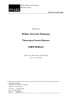
This is a typical dialog containing a Preview Image, which shows a portion of the main
image window. The preview image can be panned using the scroll bars or by dragging
with the left mouse button while holding down the CTRL key. The Zoom buttons
allow you to zoom in ( ) or out ( ).
When the Preview button is off, the image is stretched in the same manner as the main
buffer. When Preview is on, the processed version of the image has independent stretch
settings which are reflected in the Screen Stretch window. (You can click on the title
bar of the original image window to direct the attention of the Screen Stretch window
back to that image, if you need to change its stretch settings. Clicking on the command
dialog reconnects the Screen Stretch window to the Preview image again.)
Quick Stretch is also available for the Preview Image; simply point the cursor at the
preview image, hold down the Shift key, and drag the mouse up/down for brightness
1-9
MaxIm DL User Manual
and left/right for contrast.
Whenever dialog settings are changed, the image changes back to the original, and the
Preview button pops out. However, if the upper Auto button (to the left of the Preview
button) is on, the processing function is automatically applied to the preview image
whenever the dialog settings are changed. Note: if you type in a number directly, instead
of using the up/down "spin" controls, you have to hit the Enter key to get the automatic
preview. This prevents the processing from starting while you are still typing. Although
the Preview button greys out when Auto mode is on, when text is entered it is
reactivated and you can click it instead of hitting Enter.
The Full Screen preview works exactly the same way, except that the whole image is
updated. Note that you can pan, zoom, and stretch (adjust brightness and contrast) the
image. The Auto Full Screen button works exactly the same way as that for the Preview
Image. Note that processing large images may take quite a while for some functions,
such as FFT Filters; for those functions using the small Preview Image is often better.
Histogram Specification, on the other hand, is fast and it is very helpful to use the Auto
Full Screen mode with that command. Experience will tell you which method to use
with which command.
Note that the two Auto modes are mutually exclusive; you cannot use both at once.
Note: in some cases, performing a Full Screen preview causes the "undo buffer"
associated with the image to be discarded. If so, you can still Cancel the current
command and see the unmodified image, but you will not be able to Undo the previous
operation applied to this image.
Simple Mouse Tricks
MaxIm DL has a number of handy features that are accessible with the mouse, as
follows:
1-10
Introduction
To
Use
Pan
CTRL-click on the image and
hold while dragging the image.
Zoom and re-center
Right-click on the image and
select Zoom In or Zoom Out.
The image will zoom and pan so
that the spot you clicked on is
now the center.
Quick Stretch
SHIFT-click on the image and
hold while dragging up / down /
left / right.
Select a region of the image
Click and drag the mouse on
the image to select a rectangle.
The rectangle can be adjusted
by gripping and edge (move) or
a corner (resize).
Turn on Crosshairs
Right-click on the image and
select Crosshairs.
Adjust Information window
aperture
Right-click on the image to
select the aperture, gap, or
background annulus size.
Center the telescope on an
object in an image you just
exposed
Right-click on the point you
want centered, and click Point
telescope here. (Note: Autocenter must be calibrated using
the Telescope Control window.)
Lock the Information window
cursor
Double-click on the image
window. You can move the
locked cursor around using the
arrow keys. (Information
window must be open.)
Get Help on any control
Click
in the upper-right
corner of the dialog box, and
then click on any control.
1-11
MaxIm DL User Manual
Keyboard Operations
This table lists the most commonly used shortcut keys.
To
Press
Activate Help
F1
Activate Context-Sensitive Help
Shift-F1
Zoom in (limit 1600%)
PgUp
Zoom Out (limit 25%)
PgDn
Switch windows forward
F6
Switch windows backward
Shift-F6
Undo an operation
CTRL-Z
Redo an operation
CTRL-Y
Close an image
CTRL-F4
Close MaxIm DL
ALT-F4
Open a file
CTRL-O
Save a file
CTRL-S
Create a new file
CTRL-N
Access a menu
ALT-menu character
(underlined letter in menu item).
Context (Right-click) Menu
Clicking the right mouse button anywhere in an image window causes a pop up menu
(also called a context menu) to appear . The entries in this menu can vary depending on
which MaxIm DL/CCD command is currently being executed, if any, and in some cases
on exactly where in the image you clicked. The menu contains commands to manipulate
the circular cursor described in Mouse and Keyboard Operations, configure the way in
which the image is displayed, and fine-tune the pointing of an attached telescope. Other
functions appropriate to the current activity may also be included; context menu entries
of this kind are described along with the MaxIm DL/CCD command that places them
there.
The most common variety of context menu looks like this:
1-12
Introduction
The first three groups of menu items are used to control the size of the circles in the
circular cursor. To adjust the inner circle, use Increase Aperture, Decrease Aperture,
or the Set Aperture Radius sub-menu. To adjust the gap width between the aperture
and the outer background measurement annulus, use Increase Gap Width, Decrease
Gap Width, or the Set Gap Width sub-menu. Finally, to adjust the outer background
measurement annulus, use Increase Annulus, Decrease Annulus, or the Set Annulus
Thickness sub-menu.
Crosshairs simply superimposes blue vertical and horizontal lines across the centre of
the image window. These can be useful when composing a CCD image. They are never
stored as part of the image and do not affect the data, intensity measurements, etc.
The Screen Stretch sub-menu provides convenient access to the seven
presets of the Screen Stretch Window. Selecting one of these is completely
equivalent to changing the stretch mode drop-down combo box in the Screen
Stretch Window. You can use this sub-menu without having the Screen
Stretch Window open, even when working with commands that disable the
toolbar button.
Zoom In and Zoom Out are similar to the and buttons: they increase or decrease
the image 'magnification' to the next step larger or smaller. But unlike the toolbar
buttons, these scroll the image window so that the point that you had clicked the right
mouse button on is centered, as far as that is possible. Think of them as "zoom here" and
"unzoom here".
Point telescope here is enabled only when the image is the most recent image captured
from the CCD camera, a telescope is connected, and telescope centering calibration has
been performed. It slews the telescope by the necessary amount so that the next image is
centered on the point where you clicked the right mouse button. This function is more
fully explained in the description of the Center Tab of the Telescope Control Window.
Any additional context menu entries specific to the command currently being performed
1-13
MaxIm DL User Manual
normally appear at the top of the context menu.
Technical Support
Before requesting technical support, please review this manual for troubleshooting
instructions.
When requesting technical support, you must include the following information:
•
Your name as it appears on the license
•
Telephone number
•
E-mail address
•
Version of Windows
•
Any error message displayed
•
Describe step-by-step how the problem occurred. We must be able to
replicate the actions that caused the problem. If we cannot duplicate your
problem it will be very difficult to resolve it.
To submit your message, please go to: www.cyanogen.com/support.
If you do not have web access, then you can submit by fax at (613) 225-9688.
Upgrades are available free of charge from our web site for a period of one year from the
date of purchase.
Manual Conventions
In the text, Menus, commands, keys, and controls will be highlighted in bold.
“Click the mouse" always means left-click unless otherwise stated.
SHIFT-click means press and hold the Shift key while clicking the mouse. CTRL-click
means press and hold the CTRL key while clicking the mouse.
"Drag the mouse" means click the mouse and move it while holding the button
depressed. Release the mouse button when the desired effect has been achieved
(brightness adjustment, rectangle drawing, etc.).
When describing keyboard operations, CTRL-key always means press and hold the
CTRL key while pressing the designated key.
1-14
Chapter 2. Tutorials
We strongly recommend that the user read through the tutorials. They provide a basic
introduction to MaxIm DL operations, including things that may not be entirely obvious
to a new user at first glance.
The sample images used are available in C:\Program Files\Diffraction Limited\MaxIm
DL V4\Samples (assuming default installation folder).
Image Processing Tutorials
These tutorials provide a basic introduction to image processing, including opening an
image file, adjusting brightness and contrast, filtering, stretching, histogram
specification, and saving.
The Adjust Brightness and Contrast tutorial is particularly important. Since MaxIm DL
handles high bit depth images that your computer screen is incapable of displaying fully,
knowing how to adjust the image appearance is critical to using the software effectively.
Open a File
The first and most basic step is to open and display an image file.
Click on the Open button on the Toolbar to bring up the Open dialog.
2-1
MaxIm DL User Manual
Set File Filter to All Files (*.*) and turn Interpolate Pixels to Square off.
Use the Look In control to select the Samples folder under the MaxIm DL program
directory. If you used the default installation directory, this directory will be located at:
C:\Program Files\Diffraction Limited\MaxIm DL V4\Samples
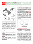
Click once on the file named “DG_HaleBopp.fits.” This is a CCD image of Comet
Hale-Bopp taken while it was still far from the sun.
The File Details box should now display information on the file size, pixel width and
height, and file format.
Click Open to open the file.
If the image does not fit within the screen area, click the Zoom Out button on the
Toolbar.
The image will appear as follows:
Adjust Brightness and Contrast
If you have not already done so, open the DG_HaleBopp.fits file in the Samples
directory. (For help on opening files see the Open a File Tutorial.)
Make sure the Screen Stretch window is visible. If it is not, click the Toggle Screen
Stretch button on the Toolbar.
2-2
Tutorials
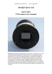
The Screen Stretch window should look something like this:
The large histogram graph at upper left shows the relative number of pixels (vertical
scale) at each intensity level (horizontal scale) in the image. The graph shows that most
of the pixels are grouped on the left (dark) side of the histogram, and that the number of
pixels drops off rapidly at brighter levels (right side).
The red caret (pointer) indicates the brightness level that is displayed as black on the
screen. The brightness level of the red caret is indicated in Minimum. Similarly, the
green caret indicates the brightness level that is displayed as white on the screen; this
brightness level is indicated in Maximum.
Click on the drop-down list with the mouse and select Low. The image should change
as follows:
The Low Stretch setting makes the image darker, allowing details in the brighter part
of the comet to be visible. Try selecting the High Stretch setting and see what happens.
Each of the three views reveals different parts of the comet. Note that selecting the
stretch mode has no effect on how the image is stored; it only changes how it is
displayed.
Quick Stretch
The fastest way to adjust the image brightness and contrast is to use the Quick Stretch
control. This method gives instant updates as the mouse is dragged, and is particularly
2-3
MaxIm DL User Manual
fast for monochrome images. The Quick Stretch control is the shaded box at the upper
right of the Screen Stretch dialog box.
Point the mouse at the Quick Stretch box and press and hold the left mouse button
down. The mouse cursor changes to a “four arrows” shape. You can now adjust the
image contrast and brightness as follows:
•
Move the mouse upwards to increase brightness
•
Move the mouse downwards to decrease brightness
•
Move the mouse right to increase contrast
•
Move the mouse left to decrease contrast
This function is also available without using the Screen Stretch window. Simply point
the mouse at any image window. Hold down the shift key, then press and hold the left
mouse button down. You can now make the same adjustments described above.
Manual Controls
Adjustments can also be made by adjusting the position of the pointers along the bottom
of the histogram. Click and drag the Green caret (pointer) under the histogram image.
This controls the brightness level that corresponds to full white on the screen; i.e. the
maximum output level. Drag it right or left; when it is dropped, the image will update
with the new settings. The Maximum field also updates to show you the corresponding
brightness level in the image.
The Red caret controls the black or background level. Try adjusting it and see what the
effect is. The Minimum field updates as you adjust the setting.
Placing the Red and Green carets close together produces a high contrast; conversely
2-4
Tutorials
placing them far apart produces a low contrast. Reversing the positions of the two carets
(Red to the right of Green) will produce a negative image.
When moving the carets with the mouse, experiment with holding down either the
SHIFT or CTRL keys. The SHIFT key makes the carets move together, keeping the
contrast constant but changing the brightness. The CTRL key makes the carets move in
opposite directions.
You can also modify the Maximum and Minimum fields directly by typing in a new
number and then pressing Enter. Note: if you type in the numeric entry fields, you must
press Enter or click Update for the new value to take effect.
When adjusting monochrome images by moving the carets with the mouse, the screen
updates as you drag the caret. When adjusting color images, the screen does not update
until you release the mouse button. Since updating color images is slower, this allows
you to make large changes without having to wait for the updates.
Notes
Remember, these functions only affect the image display. They have no effect on the
image buffer itself. This allows you to conveniently change the stretch at any time
without affecting any later image processing operations.
Tip: The Screen Stretch window is normally left turned on, and can be accessed at
almost any time – even while a dialog box is active. When a dialog box is active, you
can adjust the stretch of the Preview Image using the Screen Stretch window. In most
cases, if the Preview button is depressed, the Preview Image has separate stretch
settings. You can stretch it by clicking on the dialog box, then adjusting the Screen
Stretch window settings.
If the Preview button is not depressed, the Preview Image and main image window
share the same stretch settings.
Filtering
Filtering allows you to smooth or sharpen an image. There are several types of filters,
including FFT, Kernel, Unsharp Mask, and Digital Development. The latter two
commands are particularly useful for enhancing astronomical images.
We will demonstrate the Kernel Filters command.
If you have not already done so, open the DG_HaleBopp.fits file in the Samples
directory. (For help on opening files see the Open a File Tutorial.)
Click on the Kernel Filters button on the Toolbar. This will activate the Kernel
Filters dialog.
2-5
MaxIm DL User Manual
Using the left mouse button and holding down the CTRL key, click and drag the
Preview Image until the brightest part of the comet is visible, holding the button down
while dragging. Then turn on the Auto Preview control, and select High Pass More. A
high-pass filter sharpens the image; in this case, the image is fairly sharp already and
the filter just increases the noise, making the image "grainy".
Now select Low Pass More. The Preview Image will appear smoother. Click on
Average. The image will be smoothed slightly more. In this mode, the Kernel Size
function is available. Select 7 x 7, the strongest filter, and the preview image will
become much blurrier.
Switch back to High Pass More and click OK. After a few seconds, the entire image
will update.
If you don’t like this result, you can undo this change by pressing the Undo button on
the Toolbar.
Be sure to try the various other filters mentioned above.
Stretching
Although the Screen Stretch window allows you to adjust the brightness and contrast of
the image on the screen, sometimes you want to change the data in the image buffer. For
example, you might want to adjust an image so it will fit in the 8-bit range of a JPEG
file. You might also want to try a "non-linear stretch" to compress the dynamic range of
the image. These operations are performed with the Stretch command.
If you have not already done so, open the DG_HaleBopp.fits file in the Samples
directory. (For help on opening files see the Open a File Tutorial.)
2-6
Tutorials
Press the Stretch button on the Toolbar to bring up the Stretch dialog.
Set Permanent Stretch Type to Log, Input Range to Max Pixel, and Output Range to
16 bit (0-64K). Turn on Auto Preview. As you can see in the Preview Image, these
settings will dramatically compress the dynamic range of the image so that the brightest
and faintest parts of the comet are both visible at once.
Perhaps this setting is a bit harsh. We can better control the amount of dynamic range
compression by changing the Permanent Stretch Type to Gamma. Set Gamma Value
to 0.2 and click OK.
Now set the screen stretch to Low using the Screen Stretch window. You can toggle
back and forth between the processed and original version of the image using the Undo
and Redo buttons on the Toolbar. Notice how the faint outer details in the comet are
enhanced, but the brighter details are still visible.
Various effects can be achieved with the Stretch command; the following are some
suggestions you can try:
•
To prepare a file for export to a JPEG, BMP, PNG, or 8-bit TIFF format, set
Permanent Stretch Type to Linear Only, Input Range to Screen Stretch, and
Output Range to 8 bit. In this mode, you can adjust the Screen Stretch of the
image window to change the Input Range settings; the Min and Max fields will
update as you adjust the stretch.
•
To greatly compress the dynamic range of an image, set Permanent Stretch Type
to Log, Input Range to Max Pixel, and Output Range to Unlimited.
•
To emphasize faint features, set Permanent Stretch Type to Gamma, Input
2-7
MaxIm DL User Manual
Range to Max Pixel, and Output Range to Unlimited. Reduce the Gamma Value
to below 1.0 and adjust until you are happy with the effect in the Preview Image.
At this point, some additional explanation of the Preview Image is in order. You will
notice that the Screen Stretch window is still available; if it is not on, you can turn it on
using the button on the Toolbar. Which image the Screen Stretch window affects is
determined by the state of the Auto (Preview) push button and by where the focus is,
that is, on which window you last clicked. If Auto is off, both the image buffer and the
Preview Image always adjust together. If Auto is on, the Preview Image actually
becomes a different image and is separately adjustable. When you start a command
dialog, or after clicking on it, the Preview Image has the focus and is therefore
adjusted. If you click on the main image window or its title bar, it gets the focus and the
Screen Stretch window will now adjust it instead. To adjust the Preview Image again,
click anywhere on the dialog box.
You can also preview the result of the processing on the Full Screen. Refer to the
documentation of the Preview Image in the Command Reference for details of Full
Screen previewing.
Histogram Specification
Histogram Specification is similar to Log or Gamma stretching, but allows more direct
control by allowing you to specify the exact shape of the desired histogram.
If you have not already done so, open the DG_HaleBopp.fits file in the Samples
directory. (For help on opening files see the Open a File Tutorial.)
Click the Undo button on the toolbar to remove the stretch from the previous
tutorial.
Select the Histogram Specification command on the Process menu. Select the
Gaussian option and click OK. Since this command can significantly change the
2-8
Tutorials
dynamic range (min and max values) of the image, you may want to adjust the Screen
Stretch window settings after processing completes. In this case, setting the mode to
Low gives pleasing results.
This processing highlighted the outer tail of the comet, but did not saturate the inner
core. Histogram specification is useful for making details visible simultaneously at
greatly differing brightness levels.
Try experimenting with different settings, including manually-drawn histogram shapes.
When drawing manually, it is often easier to start from the Straight-Line or Uniform
options and then modify the graph: click on the graph shape to add a point, or move an
existing point by dragging. (If you drag a point left or right past its neighbor, the
neighbor will be removed automatically.)
Deconvolution
We will now sharpen an image of galaxy NGC4565 using Deconvolution. The image
was taken with a PC-Lynxx CCD camera and a 16-inch telescope that was out of
alignment (collimation) resulting in a distortion called coma, which makes the stars
look like “V” shapes. We will remove the effects of the collimation error and reduce the
effect of atmospheric seeing.
In this tutorial, it is assumed that MaxIm DL has just been started. (To start MaxIm DL,
click on the program icon under the Start button’s Programs sub-menu.) It is also
assumed that the toolbars are visible. If not, use the View menu Toolbar command to
switch it on.
Open the N4565.CCD image in the Samples directory. (For help on opening files see
the Open a File Tutorial.)
Click the Zoom In button on the Toolbar once. Notice how the star images are
distorted by the collimation error.
Go to the Filter menu and select Deconvolve. A tabbed dialog box will appear, with
Noise Model, PSF Model, and Deconvolve tabs.
First we need to set up the noise model. This helps the deconvolution algorithm account
for noise in the image. Enter 36.6 e-/ADU, the photoelectrons per ADU or Gain of the
CCD camera. This is necessary in order for the noise model to match the actual statistics
in the image. The value entered here is for the PC-Lynxx camera; for images from your
CCD camera you can use the Photons Wizard to determine the correct value.
Next turn on Use Poisson distribution in Maximum Entropy.
To determine the correct background level, click Auto Extract under Noise Extraction
2-9
MaxIm DL User Manual
Tools.
Next, we will choose a Point-Spread Function (PSF) model. This model tells MaxIm DL
how the image was blurred, so that it can try to remove the blur from the image. Click
the PSF Model tab. Select From Image for Function Type, turn off Clean Up, and
click Select From Image.
Adjust the circular cursor to a radius of 8 pixels (as shown in the Information
window) by right-clicking and selecting the appropriate radius. Click on the bright star
in the lower center of the image (if necessary, you can move the dialog out of the way by
dragging the title bar).
2-10
Tutorials
Click the Deconvolve tab. Set Image to Actual, and Number of Iterations to 15.
Choose either Maximum Entropy or Lucy-Richardson deconvolution. Click Go.
Watch the iterations proceed on the image. When the processing is complete, alternately
hit Undo and Redo to see what the effect is on the image.
Saving the Image
If you have not already done so, open the DG_HaleBopp.fits file in the Samples
directory. (For help on opening files see the Open a File Tutorial.)
On the File menu, choose the Save As… command. Set File Format to JPEG. Turn off
the Auto Stretch check box.
The File Details box will now show: "Warning: Selected file format cannot
2-11
MaxIm DL User Manual
accommodate largest pixel value in image. Please enable Auto Stretch or use Stretch...
button to scale image."
Now turn on the Auto Stretch check box. The message will change to, "NOTE:
Maximum pixel value exceeded. Auto Stretch will rescale image buffer."
When Auto Stretch is on, any image that will not fit into the range of the file format is
automatically adjusted based upon the current Screen Stretch settings. This means that
any data outside the range displayed on the screen will be lost, so make sure this is what
you really want to do.
(If you want to adjust the stretch manually, click the Stretch button. The Stretch dialog
will appear. If you set Permanent Stretch Type to Linear Only, Input Range to
Screen Stretch, and Output Range to 8 bit, you will get the exact same result as Auto
Stretch.)
Now click Save to save the file.
Camera Control Tutorials
The MaxIm CCD camera control window is a powerful utility with many options and
modes of operation. It is highly recommended that new users follow this tutorial to learn
the basic concepts of operating the camera.
The tutorial uses a CCD camera simulator. The simulator behaves like a CCD camera
but requires no actual hardware. It generates an image of five “stars”, and includes the
ability to add random noise to the image. It can simulate the behavior of an autoguider,
including simulating periodic error, random drift, and guiding corrections. It also
simulates the operation of a color filter wheel.
The CCD camera simulator emulates a dual-chip camera, similar to the SBIG ST-7
series. The operation is identical if you are using separate CCD cameras for the main
imager and autoguider.
You can also configure the same single-chip CCD camera to be both the autoguider and
main camera; however only one of the functions (expose or autoguide) is available at a
time. This can be handy when focusing the autoguider.
Basic Setup
1.
2-12
Start MaxIm DL and open the camera control window by clicking on the
button.
toolbar
Tutorials
2.
Move the MaxIm CCD camera control window to a convenient location on the
screen. To do this, point the mouse at the title bar, click and hold the left mouse
button, and drag.
3.
The Setup tab should appear first; if it is not displayed click on the Setup tab near
the upper right corner of the window.
4.
Select Simulator for the Main CCD camera by clicking on the associated Setup
button, and picking Simulator for the Camera Model. Also, set Noise to Off,
Guide Errors to Both, FWHM to Default (5), and Guide Angle to 45 degrees.
Click OK.
5.
Control returns to the Setup tab. Now set up the Autoguider. Click the associated
Setup button, and set the Camera Model to Same as main camera. The simulator
works like two separate cameras; one as the main camera, the other as the guider.
2-13
MaxIm DL User Manual
6.
Next set up the filter wheel. Click the Setup button, and select Filter or
Controlling Camera Model to Simulator. Type in Red for Filter 1, Green for
Filter 2, and Blue for Filter 3. Click OK.
7.
Now we are ready to connect to the equipment. Click Connect.
8.
The Simulator’s main camera has a programmable temperature. Click Cooler On
to activate it, and then click the associated Cooler button to set the temperature. Set
the temperature setpoint to –20 degrees C and click OK. Note: At the end of an
imaging session, you should click the Warm Up button and wait for the
temperature to return to ambient before turning off the cooler or disconnecting from
the camera.
9.
Once all of these settings are made they will be remembered. The next time you
want to start MaxIm CCD, just click the Connect button and then Cooler On.
Focusing
After setting up the camera and initializing the cooler, the first step in using a CCD
camera is to focus.
Tip: when using two cameras, set up the autoguider initially as the main camera and use
the built-in main camera focusing tools. Then switch it over to be the autoguider, and set
up the main camera.
1.
2-14
Select the Focus tab by clicking on it with the mouse. The Focus tab includes many
of the controls from the Expose and Settings tabs, but condensed into one compact
Tutorials
form
The Focus tab settings are completely independent of the Expose and Settings tabs.
This means that you can have two completely different sets of exposure settings and
flip back and forth quickly between the two.
2.
The simulated camera doesn’t have any dark current, so turn off the Dark control to
save time. Usually this is turned on to provide a lower-noise display, but can be
disabled to speed things up slightly.
3.
Turn Continuous mode off for now. Continuous mode takes a series of images that
can be stopped by clicking Stop. This mode is useful when you want fast updates
while you adjust the focuser.
4.
Set an exposure of 1 second using the Seconds field. You can use the up/down
"spin" control (arrow) buttons to rapidly dial from 0.001 second (0.01 seconds for
some cameras) to thousands of seconds.
5.
Set the Delay to 0 seconds. If a delay is set, there will be a brief pause between
exposures. For some cameras the controls are locked out during download to
prevent pattern noise; in this case, a slight delay may make it easier to operate the
controls, particularly in Continuous mode.
6.
Click Start Focus to take an exposure. After a few seconds, a simulated CCD image
2-15
MaxIm DL User Manual
appears.
7.
Most cameras are too slow for easy full-frame focusing. To speed up the focus
download, select a subframe. To do this, point the mouse just to the top-left of a
star, hold down the left mouse button and drag to create a rectangle around the
star as shown above. The subframe settings will be automatically entered. (You can
also automatically select a small subframe by clicking the Auto button. To restore
full-frame imaging, click Reset.)
8.
Click Start Focus. Only the selected part of the image will be downloaded. Most
cameras will operate much faster if a subframe is selected.
9.
Click on the Inspect tab.
10. The Inspect tab will show a three-dimensional representation of the star image. The
narrower the star the sharper the focus. The X, Y position of the selected star is also
shown, along with the Full-Width Half Maximum (FWHM) horizontally and
vertically, and the maximum pixel value (Max).
11. If we were connected to a real camera and telescope, we could now adjust the focus.
The Start Focus and Stop buttons duplicate those on the Focus tab; other focusing
options, including Continuous mode, must be set on that tab. Adjust focus until the
graph shows a narrow peak, the FWHM values are as small as possible, and Max is
as large as possible. Note that the Max value will usually bounce up and down due
to seeing; when very close to focus you should take the best of several readings.
Aiming the Telescope
Aiming a telescope cannot be illustrated easily in this simulation, but a few pointers are
in order.
Once the telescope is in focus, the biggest challenge can be finding your the target. CCD
cameras do not have a viewfinder, and it can be very frustrating to aim if the images
take more than about 20 seconds to appear. It can also slow things down if you have to
keep changing exposure settings. All this can be solved using the focus mode, as
follows:
2-16
Tutorials
1.
Use the Focus tab for aiming instead of the Expose tab. This way you don’t have to
keep changing the settings – the two tabs have completely separate settings.
2.
Use a high binning factor for aiming. Binning combines multiple pixels into one
"super-pixel" with greater sensitivity.
3.
Take a short exposure. With a binning factor of 2 or 3, most cameras will show a
faint but usable image with an exposure of only 10 seconds.
4.
Use the telescope hand paddle (or a software control panel) to move the image. If
you insert the camera so that North is at the top, you can orient the paddle to match.
Calibrate yourself by seeing how far a count of five will move the image. You can
then position the object just by holding down a button and counting. Note that RA
and Dec will generally have different rates.
5.
Once you’re aimed, switch over to the Expose tab and take pictures.
Note that some cameras have an optional "high-speed" mode which takes less time to
download but produces a lower quality image. Depending on the camera, this can be
enabled in the camera’s Setup dialog box. If enabled, fast readout will occur
automatically in Focus mode but not in Expose mode.
You will also want to look at the Telescope Control window. If you have a “Go To”
telescope mount, this control can make centering objects quick and painless.
Taking Exposures – Basic
Now that we have the target object focused and in our camera's field of view, it is time to
take some images. CCD cameras can collect a usable image in only 30 or 60 seconds,
but the best results are always obtained by taking longer exposures.
1.
First check your settings. Bring up the Settings tab.
2.
Click the Reset button to make sure the entire CCD chip is selected. When this tab
is visible, you can set subframe settings by dragging the mouse on the image (same
as Focus mode).
3.
Most cameras support binning, which allows you to combine pixels for higher
2-17
MaxIm DL User Manual
sensitivity at the cost of resolution. For the highest resolution, set the Binning
controls to 1. (Some cameras, including the simulator, do not support different
binning in the X and Y directions; in this case, the Y field is disabled.)
4.
Options allows you to flip or mirror the image on download, as well as lock the
MaxIm CCD window on top.
5.
Auto Calibration can be set to automatically calibrate each image as it is taken.
The Simple Auto-dark mode will automatically take a new dark frame whenever
the exposure settings are changed. For better performance, use the Full Calibration
option. This applies all the calibration capabilities of MaxIm DL’s Set Calibration
command. This is highly recommended if you want maximum performance from
your camera. For now, leave Auto Calibration off – the simulator is "perfect" and
doesn’t need any calibration.
6.
Next, switch to the Expose tab. Set Type to Light (normal image frame), dial in an
exposure of a few seconds using the Minutes and Seconds fields, set Delay to zero,
and the filter selection to Red.
7.
Click Expose and the test pattern will appear.
Taking Exposures – Advanced
We can now proceed to more advanced camera control operations.
2-18
1.
Click on the Sequence tab.
2.
This tab allows you to set up a set of monochrome, tricolor, or multi-filter
Tutorials
exposures.
3.
Enter a base file name such as “Test Image” in the Autosave Filename field. The
filenames for Individual exposures taken by the sequence will be composed of this, a
sequence number, and a filter-specific suffix.
4.
Click the Options button, select Set Destination Path from the resulting menu, and
browse to a convenient location on your hard drive to save the images. Click Open
when you have found the correct folder.
5.
Select the Setup Sequence command to configure the exposures.
6.
As shown in the diagram, enable the first three slots, and disable the rest by
clicking on the appropriate Enable check boxes. Use the scroll bar at the right-hand
side to view slots 7–16 and make sure they are also disabled.
7.
Set the exposure Type for slots 1, 2, and 3 to Light. Set their Filter selections to
Red, Green, and Blue respectively and enter R, G, and B in the corresponding
Suffix fields. When the images are taken, the suffix will be added to the end of the
file name to designate the particular slot (exposure type, filter identification, etc.).
8.
Set the Exposure time for each slot. For the purposes of this tutorial, you can set
them to 1 second so the images will appear more quickly.
9.
Set the Binning factor to 1 so the images will download in full resolution. The
range of this field is automatically limited depending on what model of camera you
2-19
MaxIm DL User Manual
are using.
10. Select Same Repeat Count for All from the Options menu at the bottom of this
dialog, then set the Repeat count of the first slot to the number of exposures to be
taken. Use 3 for the purposes of this demonstration.
11. If the Script entry for any enabled slot is non-blank, make sure Same Script Name
for All is checked in the Options menu. Then click one of the buttons and click
on None.
12. Set Delay First and Delay Between to zero. These can be set to provide delays
before the first image in the sequence, and/or between individual images in the
sequence. Delays are measured in seconds.
13. Set the desired exposure ordering. If Group by Slot (in the Options menu) is
checked, all red images will be taken consecutively, followed by all green, followed
by all blue. If Group by Slot is not checked, MaxIm CCD will take one exposure of
each color and then repeat the cycle.
14. Click OK to return to the Sequence tab.
15. Make sure none of Dither Images via Guider, Dither Images via Mount, Capture
Mosaic, Continue Mosaic or Astrometric Resynchronization is checked in the
Options menu. These are advanced features described in the reference section for
the Sequence Tab.
16. Turn on Overwrite Files in the Options menu. This makes sure that your exposure
sequence doesn’t stop if you hit a pre-existing file. Note: when operating in the
field, turn this off if you want to make sure you don’t overwrite anything; turn it on
if you want to be sure your exposure sequence never stalls.
17. Warning: Incorrect use of the Overwrite Files setting could result in lost data.
18. Select Full Frame in the Options menu. (If you wanted to use the subframe defined
on the Settings tab, you would select Subframe from Settings tab instead.)
19. Enter 1 in the Start at field. The images will be saved as Test Image001R.fit,
Test Image001G.fit, Test Image001B.fit, Test Image002R.fit, etc.
20. Now click the Start button. The camera will start taking exposures. You can
monitor the progress on either the Sequence or Expose tab. When the image
sequence is complete, check that all the files you expected to see were actually
created.
Tip: You can use the Sequence Wizard command in the Options menu to create
several different types of sequences including the tricolor RGB sequence of this
example. The Sequence Wizard performs the equivalent of steps 2–10 of the above
2-20
Tutorials
procedure.
Autoguiding
Autoguiding appears at first to be a rather complex task. However, the autoguider
controls in MaxIm CCD are actually quite easy to operate.
This tutorial demonstrates the operation with the simulator, which behaves like a dualchip CCD camera/autoguider. The operation is the same when using two separate
cameras for these functions. It is also possible to configure the same single-chip CCD
camera to operate as both the main camera and autoguider; in that case, only one
function (expose or guide) is available at a time.
Tip: When using separate imaging and autoguiding cameras, first start the guider
running. Once it is operating, switch to the Expose tab and start the camera. The guider
keeps running until you stop it, even if you are using a camera with a built-in autoguider
such as the SBIG ST-7, ST-8, ST-9, or ST-10. You can take as many exposures as you
want – you can even run a tricolor exposure sequence.
1.
Switch to the Guide tab.
2.
First, we should set up a few things. Click on the Options button and make sure
that Watch Star and Auto Dark are checked. This will cause MaxIm CCD to
display autoguider exposures during tracking so we can monitor the star. Set an
exposure of, say, 0.5 second. Select the Expose guider mode radio button and set the
Declination to zero. Select the Guider Settings command from the Options menu.
3.
Click the Defaults button and click Yes to confirm that you want to set all fields to
their recommended initial values. (The Manual Calibration and Exposure
Settings controls are excluded.) Among these are:
4.
The Cal Time controls specify how long MaxIm CCD will "hold the button down"
(i.e., actuate the telescope guiding motors) during guider calibration, before
measuring how far the star has moved. Calibration is an essential step to determine
how fast the guiding motors move the telescope and thus how much correction to
apply for a particular measured position error. (Note: if there is a speed control, it
2-21
MaxIm DL User Manual
should be set to 0.5X or 1X for guiding purposes.) Cal Time is measured in seconds
and can be specified independently for each axis.
5.
The six check boxes in the Guider Enables group are all turned on, enabling
guiding in each axis, and enabling guiding motor operation in each direction.
6.
Control Via is set to Camera Relays. This setting informs MaxIm CCD how the
guiding motors (or in this case simulator) are controlled.
7.
Display Mode is set to Pixels, with Delta should be on. This causes measured guide
star positions to be converted to errors from nominal and displayed in units of
camera pixels.
8.
Make sure Binning is set to 1 and click the Reset button to reset the subframe
settings.
9.
Select the Advanced tab of the Guider Settings dialog, click its Defaults button
and confirm that you want to set all fields to their recommended initial values. If a
filename appears in File Path, click Clear.
10. Click OK to return to the Guide tab. These settings only need to be made once;
they are remembered the next time you start the software.
11. Now click the Start button. After a few seconds the simulated Autoguider Image
will be displayed. The brightest star will automatically be selected as the guide star.
With a real autoguider, if you wanted to select a different star, you would click on
the star. Do not draw a box around it!
12. Now switch the guider mode to Calibrate, and click the Start button again. The
camera will take a series of pictures; each time moving the simulated "telescope
mount" by sending a command to the simulated "autoguider relays." The stars will
move to the right, back to center, downwards, and back to center again (with real
2-22
Tutorials
autoguiders the actual direction depends on the orientation of the camera). As it
does so, red lines are added to the Autoguider Image indicating where the guide
star has been. Each motion must be long enough (20 pixels or so) to ensure a good
calibration, but not so far as to move off the CCD chip. That is the reason for the
Cal Time setting.
13. We’re now ready to guide. Switch the guider mode to Track and click Start. The
Autoguider Image is reduced to the small 32x32 pixel image used during tracking.
You can zoom in on it using the button on the toolbar . The simulator imitates
some large guider errors, so you’ll be able to see the star moving off-center and then
being pulled back again.
14. You can now switch to the Expose tab and start an exposure. Note that a minimum
five second delay is forced for exposures on the main CCD. This is to allow time for
the autoguider to settle between exposures. If needed, this delay can be increased by
setting Delay (s) to a higher value.
A few final notes. The calibration settings change if you move the telescope in
declination. To avoid having to recalibrate for every image, you can use declination
compensation. Set the Declination field to the declination of your calibration star before
you calibrate. Then reset the Declination value whenever you change guide stars. If this
is done, you should never need to recalibrate; in fact, if you always insert the autoguider
into the telescope in the same orientation, you won’t even have to bother recalibrating
each night. If you have a "GOTO" telescope, you can configure the MaxIm DL to update
the Declination value automatically by setting Use Scope Dec in the Options menu; see
the Telescope Control Tutorial for details on connecting to your telescope.
If you have a large amount of backlash in your mount, you might want to adjust the
Backlash settings. Be careful not to set them too high, or it will make things worse
instead of better.
Shutdown Procedure
It is a good idea to properly warm up the CCD cooler before closing MaxIm DL/CCD,
unless you plan to restart the software.
2-23
MaxIm DL User Manual
To avoid thermal shock, many camera controllers have a means to gradually ramp up
the CCD chip to the ambient temperature. This can be done using the Warm Up button
on the Setup tab. The period of time required for the warm-up depends on the particular
camera model; some cameras switch off quickly, while others gently raise the
temperature over an extended period of time.
Most camera models allow you to force the cooler to switch off rapidly by clicking
Cooler Off.
Telescope Control Tutorials
Basic Control
2-24
1.
The first step is to set up a telescope. For this tutorial we will use the Telescope
Simulator. Activate the Telescope Control window using the toolbar button or
Telescope Control Window from the View menu.
2.
On the Setup tab, select Telescope Simulator from the Telescope drop list. Click
Connect.
3.
The Scope Simulator display may appear. Move this to a convenient place on the
screen.
4.
Click the Options button in the Telescope frame and click on the Slew Limits
command. Ensure that neither Minimum Altitude nor Maximum Declination are
checked.
5.
Switch to the Telescope tab.
Tutorials
6.
Click a Nudge button to move the telescope in one of the eight available directions.
You will see the telescope position change. You can set the distance moved with
each nudge.
7.
After a nudge or move, if the Take image check box is on, the MaxIm CCD
camera control window will also be activated to take a picture of the region of the
sky. (If the camera simulator is selected, you will get the test pattern). You can set
up exposure settings for these images using the Exposure button. Usually this is just
set to a quick binned exposure so you can tell whether the telescope is on target.
8.
You can enter a position in the RA and Dec fields. You can enter a Right
Ascension as hours, hours and minutes, or hours, minutes and seconds; similarly a
Declination can be expressed as one, two, or three numbers. The last number
entered can have decimal places; e.g. 12 34.5 is the same as 12 34 30. Click Go To
to start the telescope moving. Abort will stop the telescope motion.
9.
You can define the observing location by clicking the Site button. This is required
when determining the locations of the planets or if you want the telescope's azimuth
and elevation displayed in the status area. It is also recorded in the FITS header of
any images taken.
10. Now switch to the Catalog tab.
11. Set Object type to Deep sky, and click the drop-down list arrow. Pick Messier,
and type the number of a Messier object (e.g., 32). You can use the mouse and the
displayed “keypad” (convenient when working in the dark), or the computer
keyboard. Click Go To to slew to the object.
2-25
MaxIm DL User Manual
12. Click the Nearby button. This brings up the Nearby Objects dialog box.
13. In Included catalogs, turn on the Messier and NGC check boxes, and turn off the
others. Set Brighter than mag to magnitude 10, and the Max slew distance to 10
degrees. Turn off Include objects with unspecified magnitude. Click List objects.
Click on an object (e.g., NGC185) and its RA and Dec are displayed. Click on Go
To, or double-click on the object name, and the telescope will slew to the object.
14. When working with a real telescope, you can also synchronize or "align" the
telescope position. Slew to an object, say a bright star on the Named Stars list, and
center it using the Nudge controls on the Telescope tab (or see below for Auto
Center). Then click the Sync button to update the telescope controller's coordinates
to that of the object. Alternatively, use the PinPoint Astrometry function on the
Analyze menu to calculate the exact center of the image, and click Sync to align on
the measured position.
Auto Center
Auto Center permits extremely rapid object centering. This tutorial will require a real
telescope and camera operating under the night sky. We will assume that the Telescope
Control is already linked to a telescope, and the MaxIm CCD camera control window
is linked to a camera.
1.
2-26
Make sure the Telescope is synchronized on the sky so that the Right Ascension and
Declination matches the telescope position. Also make sure the CCD camera is
focused and ready to go.
Tutorials
2.
Select the Center tab. Select the Calibration Type to Auto. Set the Auto Slew
Distance to 8 arc minutes (note: if your camera has a smaller field than this, reduce
the number; it should be set to about ¼ of the field size).
3.
Locate a reasonably bright, isolated star and roughly center it in the camera. This
can be done using the Catalog tab to find the star, and the Telescope tab Nudge
controls. Set the Exposure settings to reasonable values.
4.
Click Calibrate. The software will take an image and measure the current star
position. It will then slew east and take a second image. The difference in position
between these two images will be used to calibrate the Image Scale and
Orientation. The telescope will be returned to the original position and a third
image will be taken to confirm this.
5.
Once the function is calibrated, you do not need to repeat the operation unless you
rotate the camera or change equipment. Removing and replacing the camera will
very likely change the angle, so you should recalibrate.
6.
Now you can center any object on the image. Simply right-click on it and select
Point Telescope Here from the right-click menu. The telescope will slew a short
distance. If Acquire new image after centering is checked (recommended), a
quick exposure will be taken after each centering movement.
Autofocus Tutorial
Autofocus requires a compatible digital focuser (see Telescope Control Reference). This
tutorial assumes you have the camera already linked and attached to a working
telescope.
1.
The first step is to set up the focuser. Activate the Telescope Control window using
the toolbar button or Telescope Control Window from the View menu.
2.
Select your focuser model using the Focuser drop list on the Setup tab. Click the
Focuser Options button and select the Setup command from the displayed menu to
configure the communications port if required. Click the Focuser Connect button to
2-27
MaxIm DL User Manual
establish the link with the focuser.
2-28
3.
If you have a computer-controllable telescope you can set it up and connect it as
well. This is convenient for adjusting the telescope pointing but not required.
4.
Switch to the Focuser tab.
5.
Check that you can adjust the position of the focuser. Change the Absolute position
value and click Move To. The focuser should move to the new position. You can
also adjust incrementally; set the Incremental step size to 50 and click Move In or
Move Out. Take an image with the camera to verify that the focuser is actually
moving and the focus is changing.
6.
Now switch to the Autofocus tab.
7.
Before starting autofocus, click the Settings button. There are several parameters
that must be set up correctly for autofocus to work.
Tutorials
8.
The Telescope Focal Ratio is essential. It determines the depth of focus, and
therefore the step size that is used when hunting for best focus. The focal ratio is
often found in the telescope manual; it can also be calculated by dividing the focal
length by the aperture.
9.
Also essential is the Focuser Step Size. Some digital focusers know what this is
inherently; you can click the Auto button to fill in the information. Other digital
focusers do not have this information; they are just motors hooked up to focusers
from other manufacturers. In this case, take out a ruler! Move the focuser 1000
steps, measure the distance it moves, and divide that by 1000. Enter that into the
Focuser Step Size (be sure to set Microinches or Microns as appropriate). (Tip: if
you cannot see the focuser move, as for a Schmidt-Cassegrain telescope, focus the
telescope with an eyepiece, move the focus out 1000 steps, and then pull the
eyepiece out of the focuser until the image is sharp. Measure the distance the
eyepiece is moved.)
10. You also need to set the Target ½ Flux Dia. The Half Flux Diameter is a measure
of how large the star images are, in pixels; obviously we want them to be as small as
possible. The target needs to be set somewhat higher than the optimum; typically by
2 pixels. This is required because the measurements are made on either side of
focus, not right at focus. Typical values are 5 to 7, but it depends on how small your
star images are at best focus.
11. You should also set up the exposure for the camera. In the Find mode (coarse
focus), the images are usually binned to speed up readout; usually Bin 2x2 will do.
The Subframe Width and Height are used during fine focus; smaller values speed
2-29
MaxIm DL User Manual
up the process, but if they are too small the star may shift out of the box and the
focus procedure might fail.
12. Once the settings are made, click OK to close the dialog box. Usually you only need
to set these once. After this, focusing requires but a single click!
13. Now click the Start button. Focusing takes a minute or two as MaxIm CCD first
performs coarse focusing, then switches to fine focus mode and determines the
change in star image size on both sides of the region of best focus, and finally
computes and moves to the optimum focus position. As long as there is a reasonably
bright star visible which is not ridiculously out of focus (Half Flux Diameter less
than about 70), autofocus will bring it into accurate focus.
2-30
Chapter 3. Guide to CCD Imaging
This section introduces the essential concepts required for capturing, analyzing, and
processing images using MaxIm DL.
For a basic introduction to using MaxIm DL, we strongly recommend reading the
tutorials in the previous section.
CCD Sensors
Imaging is the process of detecting light from a scene and creating a digital
representation of it. There are several types of imaging detectors in use today, but the
most common for high-performance applications is the Charge-Coupled Device or CCD.
When a photon (an individual “particle” of light) strikes an atom of silicon in the CCD
sensor, it excites an electron into a higher energy state. Because silicon is a
semiconductor; electrons are only free to move when they are in this higher energy
condition, called the conduction band. Once enough excited electrons (photoelectrons)
have accumulated, they can be read out and digitized.
In order to make a detector capable of forming images, you need more than one detector.
A CCD contains thousands or millions of light-sensitive “pixels” in an array. In a CCD
array, the pixels are defined by insulating strips in one direction, and by a set of
electrodes in the other direction. The charge in each pixel can be slid down the array
simply by changing the voltage on these electrodes. The electrons (electrical charge) that
accumulate in each pixel are shifted (coupled) from one pixel to the next until they reach
a readout register along one edge. It shifts the charge one pixel at a time into a readout
amplifier in one corner of the device. This process gives the sensor its name, the
Charge-Coupled Device.
Many modern devices use CCD detectors, such as video cameras and point-and-shoot
digital cameras. Low-light and scientific-grade imaging cameras use special techniques
to minimize noise and maximize sensitivity.
High-Performance CCD Cameras
The biggest limitation to the performance of low-light cameras is “dark current.” It
turns out that light is not the only thing that can excite electrons in the detector. Heat –
which is simply the vibration of individual atoms – can occasionally bump an electron
up into the conduction band. The warmer the array is, the more likely this is to happen;
dark current typically doubles with every 5 to 8 degrees Celsius increase in temperature.
3-1
MaxIm DL User Manual
This causes two problems. First of all, if the dark current production rate is high
enough, it will swamp the detector. Each pixel has only a limited capacity to store
electrons (the “well capacity”). For most sensors, dark current can fill the well in a
matter of seconds at room temperature.
A second problem arises because of the randomness of the dark current. Although it
accumulates at a steady average rate, the dark current is quite random. The more dark
current that accumulates, the more random noise it contributes to the image. Noise
makes it difficult or impossible to detect the signal – photoelectrons produced by
photons; in order to detect an object reliably, you need at least three times as much
signal as noise. For low-light levels and long exposures, some means of reducing dark
current is essential.
Since dark current increases with temperature, the obvious solution is to cool the sensor
down. Scientific-grade cameras typically operate at freezing temperatures – typically
anywhere from 0º C to -70º C. Some CCD sensors are specially designed to minimize
dark current and can operate near the upper part of the range; others require more
cooling. The cooling may be provided by liquid nitrogen, or by more a convenient but
less powerful thermoelectric cooler (TEC).
Large well depth is also important for good performance. For highly accurate
measurements, very good signal-to-noise ratio (SNR) is required, meaning that more
photoelectrons must be detected. A larger well allows more electrons can be collected,
resulting in more accurate measurements. Large well depth also results in greater
dynamic range; that is, the range of brightness over which the sensor will operate. At
the bottom end is the noise floor, below which the SNR is inadequate for detection. At
the top end is “saturation”, where the well fills up and may even start to bloom (bleed
into adjacent pixels). A high dynamic range is extremely important for imaging
astronomical targets, which have extreme differences in brightness levels.
Low well depth cameras limit the number of digital light levels that can be extracted
from the pixels. There is no point in recording too much below the noise floor, nor too
much above the saturation level. Smaller pixels make for lower well depths; point-andshoot digital cameras often cannot produce even 256 different discernable levels (8-bit
images). High performance CCD cameras can often produce 65536 levels (16-bit),
although quite a few cameras are marketed as being 16-bit when they cannot produce
nearly that many distinct brightness levels.
The images produced by CCD cameras are not perfect. Each pixel in each camera tends
to produce a particular voltage offset, rate of dark current production, and sensitivity to
light. These flaws can be very accurately corrected using calibration frames, one each for
offset (the bias frame), dark current (the dark frame), and sensitivity variations (the flatfield frame). Calibration makes a huge difference to the accuracy and sensitivity of the
camera; therefore calibration is also one of the most important functions of MaxIm DL.
3-2
Guide to CCD Imaging
Using CCD Cameras
CCD cameras can be difficult to use at first, particularly in astronomical applications.
This section describes some useful techniques for the efficient use of CCD cameras.
Polar Alignment
Good telescope polar alignment is important for long-exposure CCD imaging. When
acquiring targets using the small field-of-view typical of many CCD imaging systems,
accurate positioning requires good polar alignment. Inaccurate alignment also leads to
drift, which limits the amount of time an exposure can be taken before the stars begin to
blur. Even if you are autoguiding, larger drift makes for more corrections and potentially
lower guiding accuracy. Finally, with large CCD frames and high declinations, field
rotation becomes a significant factor.
Polar Alignment Scope
Many telescopes include a “polar alignment scope.” These can work reasonably well if
they are aligned properly with the mount. Unfortunately they rarely come from the
factory aligned with the polar axis, and some of these devices change alignment if the
focus is adjusted! Even if they are well adjusted, the accuracy of the polar alignment is
limited to the resolution of the alignment telescope.
Telescope mount modeling software, such as MaxPoint, builds up a model of
mechanical errors in the mounting by looking at the difference between the commanded
position and the actual telescope position. This naturally includes the polar alignment
error, which can simply be read off as a pair of numbers. Achieving accurate results
requires measuring the pointing error at a number of points spread around the sky, and
the process has to be repeated from scratch every time an adjustment is made to the
system. Although this procedure can be a little time-consuming, it does work very well if
a sufficient number of measurement points are used.
Drift Alignment
A technique known as Drift Alignment has been used for many years, and can achieve
an extremely accurate polar alignment. Unfortunately it is very time consuming, since
the drift of a star over time must be observed. This can be greatly speeded up using a
CCD camera, since sub-pixel centroid measurements can easily be made. Here is a
suggested procedure:
1.
Mount your CCD camera with north at the top.
2.
Connect MaxIm DL/CCD to the camera, configured as an autoguider.
3.
If you have an autoguider connection to the mount, remove or disable it. This
3-3
MaxIm DL User Manual
can be done by disconnecting the cable, or by going to the Guide tab Settings
and turning off Enable X and Enable Y.
4.
Point to a star at the meridian, near the equator.
5.
Start the guider in Track mode, and watch the error reading in Declination
only. It is okay to enable guiding in Right Ascension, if needed (for instance if
the star drifts rapidly out of the field of view). Due to the sub-pixel
measurement capability of the autoguider function, you will be able to see any
error quite quickly. Note which way it is moving and how quickly. (For
extremely high precision alignment for a permanent mount, you may wish to
wait several minutes to see the drift.)
6.
Now stop guiding and switch to Focus mode. Set up a very short exposure,
binned for speed, and continuous exposures. Adjust the mount in azimuth,
watching the star move. This way you can tell exactly how far you are moving
the mount (see below for calculating image scale).
7.
If the star drifts North, adjust the azimuth to the East. If the star drifts South,
adjust the azimuth to the West.
8.
Re-center the star using the telescope slow motion controls and repeat steps 4
through 6 until the drift is small.
9.
Point to a star near the East horizon, close to the equator. Make sure the star is
at least 20 degrees above the horizon, to avoid excessive refraction.
10. Start the guider in Track mode, and watch the north/south drift as before. Note
which way the star is moving, and how quickly.
11. Stop guiding and switch to Focus mode; again, use continuous, short binned
exposures. Adjust the mount in elevation, watching the star motion to see how
much you are moving it.
12. If the star drifts North, move the polar axis down. If the star drifts South, move
the polar axis up.
13. Recenter the star using the telescope slow motion controls, and repeat step 10
through 12 until the drift is small.
14. Go back to step 4 and start again, until the drift is small in both positions.
Remember to reconnect or re-enable your autoguider when you are done.
Polar Imaging
Paul Boltwood has pioneered a very simple and effective technique for polar alignment.
Using a planetarium program, create a chart of the area around the pole (north or
3-4
Guide to CCD Imaging
south). Make sure that the proper pole location is labeled on the chart.
Next, do a rough polar alignment, and then take a 60-second CCD image of the pole.
Halfway through the exposure, rotate the telescope about the RA axis as far as it will go.
Move it just fast enough to complete the arc in 30 seconds. You will create an image
with the stars clearly visible, plus a set of near-circular arcs centered on the position of
the telescope’s pole. You can now easily see the difference in position between the
telescope’s polar axis and the correct pole location. In fact, you can measure this
distance in X and Y using the Information window, and get a very accurate number.
Now adjust the mount by that distance (tip: set a rapid binned exposure mode and watch
the stars move as you adjust). After one or two iterations you have an extremely accurate
polar alignment.
PolarAlignMax
This is a new method from Larry Weber and Steve Brady, the inventors of the Half-Flux
Diameter focus measurement technique and the free FocusMax utility. It uses several
images taken across a region of the sky. The rotation of the fields is measured using the
PinPoint astrometric engine. From there, calculations are performed to determine the
location of the telescope’s axis compared to the proper pole location. Their easy-to-use
PolarAlignMax utility will work with the included PinPoint LE astrometric engine. This
utility can be obtained from http://focusmax.org.
Focusing
Focusing can be difficult because you cannot “look through” a CCD camera. Instead,
you must view the image on a computer screen. Although some CCD cameras are
capable of updating the screen multiple times a second, this is the exception rather than
the rule. At low light levels, the exposure time required is often too long. Even where a
bright target is available, the digitization circuits are often deliberately slow to give the
best low-noise performance; in other cases, simply transferring a large volume of data to
the computer takes some time.
When the screen updates only a few times a minute, it becomes extremely difficult to tell
which way to adjust the focus. Two techniques can be used to speed up the update rate.
The first – binning – combines together four or more pixels into one “super-pixel”,
producing a smaller, brighter image that can be downloaded faster. This is great for
coarse focus, but the loss of resolution makes fine focus difficult. The second method –
subframing – requires you to pick a small area of the array and only read out that region.
This also speeds up the download rate, but reduces the area available. Despite their
disadvantages, these techniques are essential for efficient focusing.
MaxIm DL/CCD provides some tools for focusing. The Focus tab provides a separate set
of exposure controls, which allows you to switch rapidly back and forth between
3-5
MaxIm DL User Manual
focusing and normal imaging. The Inspect tab allows you to view the quality of focus
both graphically and numerically. Of particular interest is the Half-Flux Diameter and
Full-Width Half Maximum measurements, which tell you the diameter of a star image.
The focus is simply adjusted for the minimum star size.
To speed up the focusing process, it is helpful if the focus is approximately correct
before you start. A useful technique is to “parfocalize” an eyepiece with the CCD
camera. First carefully focus the camera using the standard techniques. Next, without
changing the focus settings on the telescope, remove the camera and replace it with an
eyepiece. Depending on the eyepiece, it may be necessary to use an extension tube.
Without adjusting the focus setting, slide the eyepiece in and out until focus is achieved.
Now mark the point of best focus on the eyepiece barrel. The best way is to make a small
metal ring with setscrews that can be locked in place. The next time you need to focus,
use this special eyepiece first, and visually adjust the focus to the approximately correct
position. Now only a small refinement is necessary.
In the past, manual focusing was the most tedious and time-consuming part of CCD
imaging sessions. However, this has changed with the advent of reliable autofocus
techniques. The SharpStar autofocus capability of MaxIm DL/CCD can reliably focus
as well as or better than manual focusing. It does require a digitally controlled focuser.
Some less-expensive motorized focusers can also be used for autofocus, by using the
FocusMax add-on. This free program is highly recommended, and can be downloaded
from http://FocusMax.org.
Aiming
Aiming a CCD camera can be difficult, since there is no facility to “look through” the
camera. The Focus tab can be a very useful tool for aiming. Once the camera is focused,
set up the Focus tab to take a very short duration, binned image. You can then switch
quickly back and forth between the Focus tab and the Expose tab, which is usually set up
to take a long, high-resolution exposure. Although the focus frame will be a very short
exposure, the use of binning will boost the signal-to-noise ratio and make it possible to
see faint objects. This will allow you to easily take a quick snapshot to help with aiming.
If you have a GOTO telescope, several helpful features are available.
You can use PinPoint Astrometry as a digital finderscope. If you slew to an object but it
does not appear on the chip, perform a PinPoint reduction using the Spiral Search
option. Once PinPoint has found the solution, switch to the Telescope Control window
and press Sync. You will be asked if you want to sync to the PinPoint solution. Click OK
to align the telescope’s controller to the accurate PinPoint measurement, and then click
the GOTO button again.
If your object appears on-chip but not centered, you can use the Auto Center feature of
3-6
Guide to CCD Imaging
the Telescope Control. Once Auto Center is calibrated (Center tab), you can right-click
the object on the image and select Point telescope here. The telescope will be slewed to
move the point you clicked on to the center of the image. (If there is significant backlash
in the mount, you may need to do this a second time.)
You should also consider using MaxPoint, which is available at extra cost
(www.cyanogen.com). MaxPoint models the errors in a telescope mount and corrects for
them. Even on inexpensive GOTO telescopes, you can easily achieve pointing accuracies
of 1-2 arc-minutes, which is sufficient to put objects near the center of your CCD sensor
over the entire sky.
Autoguiding
When taking long exposures on astronomical telescopes, tracking is required to
compensate for the Earth’s rotation. Typical astronomical telescope mounts are not
accurate enough for long exposure imaging without some form of guiding.
Tracking errors are usually sufficiently small on short duration images (15 to 90 seconds
depending on the mount) that guiding is not required. Therefore a series of short
exposure images can be taken and combined together later using the Combine Files
command. However, in many cases a single long exposure is superior due to the
elimination of extra readout noise and the residual blurring caused in realigning the
images.
Although telescopes can be guided manually, many observers are now using CCD
autoguiders. In some cases these are stand-alone units that are interfaced directly to the
telescope. However, some units can or must be controlled from software. MaxIm CCD
provides support for several different CCD autoguiders, and can run them in parallel
with the main camera.
Instructions for installation of the autoguider are included with the unit. Generally
speaking, the autoguider connects electrically to the telescope’s guide controller using a
standard RJ-11 jack. In some cases, special connections are required. Many GOTO
mounts can be controlled using the Telescope Control window. Optically, the autoguider
is connected either to a guide telescope attached mechanically to the main telescope, or
to an off-axis guider. The off-axis guider includes a pick-off mirror that diverts light
from the telescope into the autoguider. Normally the pick-off mirror is positioned
outside of the main camera’s field of view.
Some cameras include two autoguider sensors, either in the same package or not, with
both operating through the same interface. Most SBIG camera models work this way, as
do some Starlight Xpress cameras. If both sensors are looking through the same
instrument, this ensures that mechanical flexure is not an issue, although limited fieldof-view and losses due to filters can be a problem.
3-7
MaxIm DL User Manual
Focusing
Focusing is not as critical for autoguiding as for imaging; however, poor focus can result
in a loss of sensitivity.
For dual-chip SBIG cameras and STAR2000 equipped Starlight Xpress cameras, the
tracking CCD is automatically in focus once the main camera is focused.
For all other cameras, you can use the Focus and Inspect tabs to help with focusing the
guider. The Inspect tab provides a variety of tools for determining best focus.
Autoguider Calibration
In order to properly control the mount, MaxIm CCD must calibrate the system. The
exact orientation of the autoguider, the focal length of the guide telescope optics, and the
speed of the motor drive all affect the calibration.
For best results, place a bright star in the field of view of the autoguider imager, near the
center of the field. Take an exposure using the Guide tab’s Expose mode; the guide star
will be picked automatically, or you can click on one using the mouse. Now start the
calibration function by selecting the Calibrate mode and clicking Start. MaxIm CCD
will take a series of five full-frame exposures, moving the mount between each exposure.
This will allow it to determine how fast the mount moves in each direction. The motion
between successive exposures are in the +X, -X, +Y, and then -Y direction.
The star must move at least five pixels between each exposure for an accurate
measurement, and preferably more. If the star does not move at least five pixels, an error
message will be displayed at the end of the calibration cycle. The algorithm can be
confused if another star appears in the frame; to minimize this risk, it always uses the
star with the brightness most similar to that measured in the first image.
If the star does not move far enough, or moves too far (i.e. the star leaves the field), the
duration of the calibration move commands can be adjusted by clicking the Settings
command and changing the Cal. Time fields (measured in seconds). A longer
calibration time will increase the motion of the star; a shorter time will decrease the
motion. Typical values range from five to ten seconds, depending on the correction
speed, focal length, and pixel size.
Using the Guide tab’s Settings dialog, you can also set a Backlash setting to run out
any backlash caused by changing the direction of motion (also entered in seconds). See
below for more information.
The Aggressiveness control on the Guide tab allows you to adjust how vigorously star
motions are tracked out. An Aggressiveness setting of 10 means that the autoguider
attempts to track out 100% of the motion, whereas a setting of 1 means that the
autoguider only tracks out 10% of the motion. Usually a setting of around 8 or 9
3-8
Guide to CCD Imaging
provides the best tracking, since it reduces overshoot and helps ignore random motions
due to atmospheric seeing and wind loads. You may have to reduce it further if for some
reason your calibration is inaccurate (this could be caused by significant backlash). You
should experiment to determine the best setting for your particular telescope.
The calibration may also be adjusted manually using the Settings command. The X
Speed and Y Speed parameters allow you to enter the apparent speed of motion of the
star during guide corrections in pixels per second. For example, if the star moves three
pixels in one second, the speed is 3 pixels per second. The number can be negative if a
positive correction causes a negative motion. If the autoguider sensor is not aligned with
the telescope axes, the rotation angle is entered in Angle (deg).
Backlash and Stiction
Backlash can occur when the direction of motion on an axis is reversed. The telescope
may not immediately start moving in the reverse direction, even though the motor is
turning. The usual cause is loose meshing of the gears in the drive train. In the case of
worm gears this can often be largely adjusted out; unfortunately in some cases, attempts
to adjust the gears can result in too much friction resulting in motor stalls. If the
backlash is inside a gearbox it generally cannot be fixed without redesigning the drive
system.
Generally backlash is only an issue on the Declination axis, because the Right Ascension
axis is always moving forwards due to sidereal tracking.
Backlash can be compensated for – to a degree – in software. If the drive takes 1.2
seconds to turn around, the software could automatically add 1 second of drive time
whenever the direction changes. A suitable backlash time can be entered into the Guide
tab Settings dialog box for each axis. This number is used for both calibration and for
guiding. You should always set this to less than the estimated backlash time; if it is too
high, it will result in chronic overcorrection. If in doubt, set it to zero.
Note that some mount drive systems include built-in backlash compensation. It is
recommended that this be turned off during autoguiding.
The term “stiction” comes from “static friction.” Static friction occurs when two objects
in contact are at rest or moving very slowly relative to each other. Dynamic friction
occurs when the two objects are in motion. Static friction is always larger than dynamic
friction, so when an object starts moving, the amount of friction present can change very
rapidly. An example of this happens when you brake your car. Just before the car stops,
you have to let up on the brake pedal; otherwise the car jolts to a stop (if you’ve been
driving for years, you may not even be aware you are doing it).
Stiction occurs between the teeth in a gear system. Of particular interest here is the
effect on worm drives, which are typically used in astronomical telescopes. When the
3-9
MaxIm DL User Manual
drive is stationary, the gears “stick together.” When the worm starts rotating, it pulls on
the teeth of the worm wheel. In this situation, the wheel can bend, or the mounting or
bearings can flex, at right angles to the normal rotation. The resulting motion is usually
backwards – you try to move the mount North, and it goes South! This only happens for
a brief period of time after reversing directions; eventually the worm turns enough that
the gear is forced to move in the correct direction.
Stiction problems can be complex mechanically; it can often be hard to determine what
the root cause is. Many telescope mounts – even high-end models – suffer from this
problem, and it may vary between different samples of the same model. The problem has
a terrible effect on guiding because it forces overcorrection, and it cannot be effectively
solved in software.
If you experience bad guiding in declination and cannot resolve it through adjusting the
calibration or aggressiveness, you may have a stiction problem. One solution that works
is to note the average drift in declination, and disable corrections in that direction. The
guider should only be able to push against the average drift, not with it. This works
surprisingly well. Some users deliberately adjust their polar alignment slightly off to
ensure that the drift is in a consistent direction. You should avoid large offsets that may
cause field rotation.
You can disable one guide direction by clearing the appropriate Output checkbox in the
Guider Settings section of the Guide tab Settings dialog. These check boxes only
affect tracking corrections, not calibration, so you do not have to re-enable the direction
in order to calibrate the guider.
Declination Compensation
When the telescope is pointed near the pole, the apparent motion of the stars slow down.
This can be easily seen by noting that Polaris is almost stationary. Unfortunately, this
variation in speed affects the calibration of the autoguider. If you calibrate at the equator
and then move to a polar region, the autoguider will compensate too slowly in RA. If
you calibrate near the pole and then move to the equator, the autoguider will badly
overcompensate. Either situation can lead to poor guiding.
The obvious way to overcome this is to recalibrate prior to each exposure. This is timeconsuming and largely unnecessary. The recommended procedure is to calibrate once
and use the Declination field to adjust for the position of the telescope.
When you first calibrate, you should do so on a star near to the equator. Enter the
declination of the calibration star in the Declination field. When you move to a different
position on the sky, reset the Declination field to match the new telescope position.
MaxIm CCD will now automatically adjust its calibration to compensate for the change
in telescope position. Whenever you reposition the telescope, adjusting this field to
3-10
Guide to CCD Imaging
match the declination of the telescope will eliminate the need to recalibrate.
If you have an active link to a telescope in the Telescope Control window, the
Declination field will be automatically filled in for you.
When using German Equatorial mounts, it is necessary to rotate the telescope 180
degrees to switch between East and West. This affects the calibration of the guider since
it reverses the apparent direction of motion on the RA axis. The Pier Flip control can be
used to compensate for this if the X axis outputs are connected to the RA axis of the
telescope (the usual convention). Simply toggle this control when you flip the telescope
over the mount.
Troubleshooting
Autoguiding is a deceptively complex operation, since it is a two-axis closed loop servo
system with troublesome mechanical problems like backlash and stiction.
A detailed step-by-step guide to diagnosing autoguiding problems is included in the
main Troubleshooting chapter.
Here are some quick things to check:
•
Use the Graphical Track Log to monitor guiding performance. See if
problems are happening in Right Ascension or Declination, or both, and
whether there is any pattern to it. Periodic behavior suggests incorrect
calibration or too high aggressiveness. Sudden jumps suggest a mechanical
problem such as backlash, stiction, or mount balance.
•
For most mounts, set the Aggressiveness between 5 and 8. You can adjust
the Aggressiveness during tracking to see what effect it has.
•
If the mount has built-in backlash compensation, turn it off. If you are not
sure how to set the MaxIm CCD backlash controls, set them to zero.
•
Make sure the guide rate on the mount is between 0.1X and 1X.
•
During calibration make sure the guide star moves in an “L” pattern and
moves at least 10 pixels – preferably 20 or more – on each leg.
•
Make sure that your mount is balanced so it is slightly heavier on the East
side. This may require rebalancing when you flip a German Equatorial
mount over the pier.
•
Some mounts have significant stiction on the Declination axis. Stiction
causes the mount to continue to move forwards briefly when you reverse
directions. A common solution is to disable declination corrections in one
direction only. You should disable the direction that pushes in the same
3-11
MaxIm DL User Manual
direction as the average drift. You can disable one direction using the
Guide Tab, Settings, More. Some observers even deliberately offset their
polar alignment slightly to ensure a very slow drift.
•
You can adjust the mount response in RA and Dec separately by tweaking
the manual calibration parameters. The number displayed is the rate of star
movement during tracking in pixels per second. If the axis is
overcorrecting, increase the number; if it is undercorrecting, decrease the
number.
•
Try adjusting the rate at which updates are sent to the mount. Some
mounts work best with multiple updates per second, while others work
better with a slower update rate. For example, LX200 mounts generally
work best with a 3 second update rate. In most cases you can simply
increase the guider exposure time to slow down the updates; however, a
delay-after-correction function is available if needed.
Image Scale
To obtain the best images, it is very important to match your CCD camera to your
optical system. While wide-field panoramas are certainly possible with a CCD camera,
the high sensitivity makes them particularly well-suited to high resolution imaging.
Resolution depends on both the focal length of the telescope, and the size of the pixels in
the CCD array. Long focal lengths and small pixels result in higher resolution. Too
much resolution and the images will be fuzzy. Too low resolution and you will not be
achieving the full potential of the instrument – you may even end up with small squarelooking stars.
Often the matching can be adjusting by using auxiliary optics (reducers and barlows) or
binning. The key to good performance is achieving proper Nyquist sampling.
Nyquist Sampling
The Nyquist Sampling Theorem sets the fundamental limits on any system that digitizes
signals, whether it be a CD player, a telecommunications system, or a CCD camera. The
theorem tells you how fine sampling is required to produce a “perfect” representation
with no loss in quality.
The American physicist and electrical engineer Harry Nyquist proved that if the
sampling is at least twice the highest spatial frequency component in the image, no
distortion will occur and you can reconstruct an exact replica of the original image. The
theorem really requires the image to be filtered (smoothed) to remove any higher
frequency components; but in practice, the limitations of the optics and seeing take care
of this for you.
3-12
Guide to CCD Imaging
For that reason, for optimum performance, you need to have at least two pixels across
the core of a star image. By “core” we mean the Full-Width Half Maximum (FWHM);
i.e. the diameter at which the star intensity falls to one-half its peak value. For practical
purposes, the sampling really needs to be 2.5 to 3 pixels across the FWHM. For high
performance applications, such as profile-fitting photometry, even higher sampling is
required to represent the exact shape of the star image.
There is a second part to the Nyquist Sampling Theorem – the image you capture isn’t a
perfect representation of the original image; it just contains all the information
necessary to reconstruct it. To properly view the image, you need to pass it through a
reconstruction filter. In a digital system, this can be done only by resampling the image
to a higher resolution and then low-pass filtering it. MaxIm DL can do this with the
Double Size command.
Matching Small Optics
For small optics (microscopes, telescopes under 10 cm or 4 inches), the focal ratio is the
important factor. The pixel size needs to match the spot size, which for a perfect optical
system is the diameter of the Airy disk, the image created by a perfect point source such
as a star. The spot size can be calculated with the following formula (assuming a
wavelength of 550 nm):
spot size (microns) = 1.38 * f/ratio
If you adjust the focal ratio so that the spot size is at least twice the pixel size, you will
have adequate sampling.
Matching Large Optics
The effects of seeing, the random star motion caused by atmospheric turbulence,
increases the practical spot size for larger instruments. In this case, the seeing disk in
arc-seconds and the focal length are the important parameters. You can calculate the
size of a pixel in arc-seconds using the following formula:
pixel size (arc seconds) = 206 * pixel size (microns) / focal length (mm)
(The result can be quickly estimated by rounding off the constant in the equation to 200.
For example, suppose a camera with a Kodak KAF0401 sensor, which has a pixel size
of 9 microns, is attached to a telescope with a focal length of 2000 mm. The pixel size is
9 * 200 / 2000 = 0.9 arc seconds.)
For long-exposure astronomical imaging at most sites, the seeing disk is often up to 3-4
arc seconds across. Typically an image scale of 1-2 arc-seconds per pixel is optimal. At
superior sites you can use 0.5 arc-seconds per pixel; however, imaging at this level
requires excellent optical quality and a very stable mounting or a high-speed tip/tilt
3-13
MaxIm DL User Manual
guider such as the SBIG AO-7.
Planetary Imaging
The short exposures used during planetary imaging can “freeze” the seeing and allow
full-resolution imaging even with very large instruments (assuming good optics). For
planetary imaging with short exposures, start with an image scale of 0.25 arc seconds
per pixel; use trial-and-error to determine the best image scale for your equipment,
conditions, and the planet being imaged. Since seeing is highly variable, it is
recommended to take many exposures and keep only the best.
Using Multiple Exposures
The simplest way to take a long exposure is to simply open the shutter for the desired
duration. Taking a single exposure certainly minimizes the contribution of camera
readout noise in the image.
However, for astronomical imaging two difficulties are often encountered. First of all,
the telescope must remain aligned with the sky to a fraction of an arc-second throughout
the exposure. This is extremely difficult (expensive) to achieve mechanically, so in most
cases some form of guiding is required. Secondly, bright stars within the frame will
rapidly saturate and bloom. This affects not just the saturated pixels but also adjacent
ones as the excess electrons become trapped and spread along the column during
readout.
Both these problems can be greatly reduced by taking a series of shorter exposures, then
combining them together afterwards. MaxIm DL provides support for this in the form of
the Combine command. This command allows you to combine a number of images into
one equivalent long exposure. The image alignment feature allows you to remove the
effect of telescope drift, and the floating-point representation used means that saturation
can be avoided.
Many telescope worm gears have positions where there is some relatively rapid drift. If
some of the shorter images are unsuitable due to trailing, they can be examined and
removed from the sequence using the Combine command. All of the images should be
calibrated before combining them.
Color Imaging
A few cameras on the market are single-shot color cameras. Each image from the
camera is encoded with color information. This is achieved by placing microscopic
filters over the individual pixels on the chip. The Convert RGB and Convert MX
commands can be used to transform these encoded images into color.
The conventional way to take color images with a CCD camera is to use a set of Red,
3-14
Guide to CCD Imaging
Green, and Blue filters. Individual images are taken through these filters and combined
in software. MaxIm DL/CCD has extensive features to support RGB color imaging.
LRGB Imaging
In LRGB imaging, a Luminance (L) frame is added to the standard RGB mix. The
Luminance fully or partially replaces the luminance information from the filtered
images. Often the Luminance image is taken with a longer exposure. The RGB images
are sometimes binned to allow shorter exposures. Since the human eye has lower
resolution in color than in luminance, the difference between binned and non-binned
RGB components is generally not discernable. (Note: binning is often counterproductive on moderate to long exposures due to photon shot noise from the sky
background. Experimentation is recommended to determine the best approach for your
observing site and equipment.)
MaxIm DL fully supports automated LRGB imaging via the Sequence tab. You can
configure different exposure and binning settings for the various filters. When
combining the L frame with the RGB frames using Combine Color, MaxIm DL can
automatically rescale the binned color frames to match the luminance frame.
CMY Imaging
An alternative technique that has been promoted in recent years is the use of Cyan,
Yellow, and Magenta filters. The advantages quoted include wider bandwidth resulting
in more light and therefore higher signal-to-noise ratio. CMY imaging is fully supported
in MaxIm DL.
Unfortunately there are several problems with CMY filters. To build a usable RGB
image from the CMY set, the images have to be added and subtracted from each other.
Since the noise in the three channels is uncorrelated, the resulting noise in each R, G,
and B channel is larger than that in the CMY channels. As a result, the improvement in
SNR is extremely tiny, and is not worth the extra effort required.
CMY filters have additional complications. Attaining an accurate color balance with a
subtractive system in the presence of the varying sensitivity of the camera across the
band is a difficult proposition. Also atmospheric dispersion effects will be worse with
the wider filters. As a result, although MaxIm DL supports CMY imaging, it is not
recommended in practice.
Infrared Sensitivity
CCD cameras are very sensitive to near-infrared light. This can lead to an unexpected
problem with reflections inside the optical instrument. Generally optical systems have
flat black inside surfaces and baffles to absorb stray reflections. Usually metal parts are
3-15
MaxIm DL User Manual
anodized black; unfortunately most types of anodizing are highly reflective in the
infrared. The result is that the camera can see the reflections, but the human eye cannot.
This type of reflection can be most troublesome when trying to perform flat-field
calibration, generating a “hot spot” in the center of the image.
The simple solution to this problem is to paint the anodized surfaces flat black. This is
particularly important for tubular structures just in front of the camera. A baffle can also
be added just in front of the camera to block stray light, but care must be taken to avoid
vignetting.
When taking tricolor images using a CCD camera, it is important to note that most blue
filters strongly leak infrared light. Therefore an infrared blocking filter is essential.
Some modern filters include a built-in infrared blocking layer.
Signal to Noise Ratio
A CCD camera is essentially a photon counting device. Signal to noise ratio (SNR) can
be calculated by summing over all the pixels within an aperture as follows:
SNR =
S T
S+
∑ (B + D + R
2
t)
where:
S = signal in photoelectrons
B = sky background in photoelectrons
D = dark current in electrons
R = readout noise in electrons
T = total integration time in seconds
t = integration time per image in seconds
A signal-to-noise ratio of three is usually considered the minimum for detection. A
higher SNR is required for photometric measurements.
This has several implications for CCD imaging:
3-16
1.
Best SNR performance is achieved by keeping the star size small, subject to the
Nyquist criterion (at least 2.5 pixels across FWHM).
2.
On very short exposures, or sequences of short exposures, the readout noise
performance may be the limiting factor.
3.
In most cases, for long exposures the sky background is the limiting factor for
performance, even at dark sky sites.
4.
If properly calibrated, dark current noise is usually only important for narrowband
Guide to CCD Imaging
imaging (spectroscopy, narrowband interference filters, etc.).
To improve performance in the read-noise limited case, consider increasing the exposure
(particularly if summing a sequence of exposures).
In all cases, increasing telescope size, camera quantum efficiency, or exposure time will
improve your limiting magnitude (faintest detectable objects).
Bit Depth
Most CCD cameras produce 16-bit images, with pixel values ranging from 0 through
65535. Subsequent processing can increase the bit depth beyond this point.
By default, images taken with the CCD camera are saved in FITS 16-bit format. If you
perform processing that increases the bit depth, you should save in FITS IEEE Float
format.
Novice users often have trouble saving images in formats like JPEG, which can only
handle 8-bit data. The File menu Save As command warns you in a text box when the
data in the image exceeds the capabilities of the file. If this happens, make sure the
Screen Stretch is set appropriately, and turn on the Auto Stretch check box. The image
will automatically be scaled so the saved image will look just like the image on-screen.
Note that when this is done, data precision is permanently lost. It is strongly
recommended to first save your images in a high bit depth format like FITS or 16-bit
TIFF, so that you do not lose data.
Image Processing Basics
Most image processing functions either adjust the range of all pixels together
(stretching) or modify pixels based on the value of their neighbors (filtering). This
section introduces the basic concepts and explains some of the variations available for
each technique.
For information on using these functions to best effect, please see Advanced Image
Processing.
Stretching
The single most important image processing function is known as stretching. In its
simplest form, stretching is the same as adjusting the brightness and contrast of your
television. Your television has these controls because it cannot display the world as it
really is. Unlike your eyes, which can work on a sunny day or a moonless night, a
television can handle only a very limited range of brightness. The huge dynamic range
of the eye has never been duplicated by video display technology.
3-17
MaxIm DL User Manual
While video displays and printers still suffer from this severe limitation, the cameras do
not. Modern high-performance CCD cameras can record up to 65,536 different
brightness levels, yet most computer monitors can only display about 64 brightness
levels (even if more levels are available, they usually cannot be distinguished on the
monitor). This huge gap can be bridged using stretching techniques.
Basic Stretching
In its simplest form, stretching works as follows. A typical CCD image represents each
pixel as a number from 0 to 65,535. This has to be mapped into the video monitor’s
range of 0 to 255. A simple formula is applied to each pixel:
New Value = Old Value X Scale + Offset
If the resulting new value is greater than 255, it is set to 255. If it is less than zero, it is
set to zero. The Scale and Offset numbers control how the image appears on the screen.
Where do these two "magic" numbers come from? The user provides them by trial-anderror. Although MaxIm DL can try to determine the settings for you automatically, the
best results are obtained by tweaking the numbers until the most pleasing display
appears.
Whirlpool Galaxy – Two Different Stretches
In MaxIm DL, the numbers are entered a bit differently. The two values entered are
Minimum and Maximum. A pixel that is at the minimum value is set to zero, and a
pixel at the maximum value is set to 255. This method is more convenient because it
leads to a simple way to display the stretch numbers graphically using a slider bar. In
MaxIm DL, this slider bar appears in the Screen Stretch window (histograms are
described below).
Instead of entering numbers, it is faster to use the Quick Stretch facility. This allows
you to modify the image appearance with small up/down and left/right movements of the
mouse. To do this, hold down the Shift key, then click and drag the mouse on the
3-18
Guide to CCD Imaging
image.
The problem with stretching is determining exactly how to stretch the image for best
effect. Often there are several different possibilities for the same image. For example,
two different views of the same image of the Whirlpool Galaxy (M51) are shown above.
The first image reveals all the detail in the spiral arms, but the core of the galaxy is
burnt out. In the second image the spiral arms are all but gone, but now we can see the
supernova adjacent to the core of the galaxy.
Histograms
To better understand the more complex stretching techniques, it is helpful to understand
histograms. A histogram is a simple bar graph that shows the range of brightness in an
image. Each bar in the graph represents a range of brightness; the first bar represents
the dimmest pixels, and the last bar is for the brightest pixels. The height of the bar is
the total number of pixels in that brightness range in the image. Every image has a
different histogram depending on how much of the image is bright or dark.
Typical Histogram
A typical histogram will have a peak that shows the most common brightness in the
image. For astronomical images this is often the sky background. A part of the
histogram where there is a dip reveals that few pixels have brightness in that range.
When stretching, we do not want to emphasize those areas because they contain little
information.
Any stretching operation can be viewed as reshaping the histogram. Some functions do
this in a fixed manner; others actually force the histogram to have a particular shape.
Both types of techniques will be described below.
Nonlinear Stretching
When we do a stretch we can do much fancier things than just subtracting and
multiplying numbers. A popular method is called "log rescale". All pixels in the image
are put through a logarithm function. This may seem like an arbitrary choice, but there
are reasons for choosing it. The astronomical magnitude scale is logarithmic so that it
3-19
MaxIm DL User Manual
can encompass a wide range of brightness. The human eye itself responds to light in a
fashion that is close to logarithmic.
Before and After Gamma
What the log rescale function does is stretch different parts of the images differently.
This allows you to see the bright details – at lower contrast – while still seeing the faint
details. The logarithm function actually changes the shape of the histogram itself.
On many images log rescale is a bit aggressive – the image will look washed out. In
some cases we might even want to do the opposite, highlighting bright objects at the
expense of faint details. Gamma correction is a more general technique. It is related to
log rescale in that it also uses logarithmic functions, but it is a bit more complicated. A
number, called Gamma, controls the exact shape of the curve.
Histogram Specification
All stretching operations can be visualized by looking at the effect on the histogram. We
can modify the shape of the histogram to improve the view of the object. By using a
process called histogram specification we can make the histogram flat, sloped, or any
curve we want.
The process is similar to how some teachers "bell curve" marks. The students are listed
by order of grade on the exam. The top student on the list gets 100%, the next 99%, and
so on. If the teacher wants most of the class to get a mark near 75%, she can assign
more students grades in the 70-80% range. With this technique, the student's final grade
depends on his rank in the class, not on the actual mark. The teacher can generate any
distribution at will.
When the same process is applied to images, it allows us to force any shape onto the
image histogram. This technique is particularly useful for compressing out regions of
the histogram that have very few pixels.
3-20
Guide to CCD Imaging
Spatial Filtering
Spatial filtering is widely used for extracting detail and controlling noise. Filtering is
not like stretching, which works on each individual pixel in isolation. When filtering an
image, each pixel is affected by its neighbors. This actually moves information around
the image.
Low-Pass Filtering
The most basic of filtering operations is called "low-pass". A low-pass filter, also called
a "blurring" or "smoothing" filter, averages out rapid changes in intensity. The simplest
low-pass filter just calculates the average of a pixel and all of its eight immediate
neighbors. The result replaces the original value of the pixel. The process is repeated for
every pixel in the image.
Before and After Low-Pass Filter
This low-pass filtered image looks a lot blurrier. But why would you want a blurrier
image? Often images can be noisy – no matter how good the camera is, it always adds
an amount of “snow” into the image. The statistical nature of light itself also contributes
noise into the image.
Noise always changes rapidly from pixel to pixel because each pixel generates its own
independent noise. The image from the telescope isn't "uncorrelated" in this fashion
because real images are spread over many pixels. So the low-pass filter affects the noise
more than it does the image. By suppressing the noise, gradual changes can be seen that
were invisible before. Therefore a low-pass filter can sometimes be used to bring out
faint details that were smothered by noise.
MaxIm DL allows you to selectively apply a low-pass filter to a certain brightness range
in the image. This allows you to selectively smooth the image background, while leaving
the bright areas untouched. This is an excellent compromise because the fainter objects
in the background are the noisiest, and it does not degrade the sharpness of bright
foreground objects.
3-21
MaxIm DL User Manual
Filtering can be visualized by drawing a “convolution kernel”. A kernel is a small grid
showing how a pixel's filtered value depends on its neighbors. To perform a low-pass
filter by simply averaging adjacent pixels, the follow kernel is used:
+1/9
+1/9
+1/9
+1/9
+1/9
+1/9
+1/9
+1/9
+1/9
When this kernel is applied, each pixel and its eight neighbors are multiplied by 1/9 and
added together. The pixel in the middle is replaced by the sum. This is repeated for each
pixel in the image.
If we didn't want to filter so harshly, we could change the kernel to reduce the
averaging, for example:
0
+1/8
0
+1/8
+1/2
+1/8
0
+1/8
0
The center pixel contributes half of its value to the result, and each of the four pixels
above, below, left, and right of the center contribute 1/8 each. This will have a more
subtle effect. By choosing different low-pass filters, we can pick the one that has enough
noise smoothing, without blurring the image too much.
We could also make the kernel larger. The examples above were 3x3 pixels for a total of
nine. We could use 5x5 just as easily, or even more. The only problem with using larger
kernels is the number of calculations required becomes very large.
A variation on this technique is a Gaussian Blur, which simply allows you to define a
particular shape of blur kernel with just a single number – the radius of a Gaussian
(“normal”) distribution.
High-Pass Filtering
A high-pass filter can be used to make an image appear sharper. These filters emphasize
fine details in the image – exactly the opposite of the low-pass filter. High-pass filtering
works in exactly the same way as low-pass filtering; it just uses a different convolution
kernel. In the example below, notice the minus signs for the adjacent pixels. If there is
no change in intensity, nothing happens. But if one pixel is brighter than its immediate
3-22
Guide to CCD Imaging
neighbors, it gets boosted.
0
-1/4
0
-1/4
+2
-1/4
0
-1/4
0
Unfortunately, while low-pass filtering smoothes out noise, high-pass filtering does just
the opposite: it amplifies noise. You can get away with this if the original image is not
too noisy; otherwise the noise will overwhelm the image. High-pass filtering can also
cause small, faint details to be greatly exaggerated. An over-processed image will look
grainy and unnatural, and point sources will have dark donuts around them. So while
high-pass filtering can often improve an image by sharpening detail, overdoing it can
actually degrade the image quality significantly.
Low-pass and high-pass filters are both available from MaxIm DL's Kernel Filter
command, together with some related variants.
Unsharp Mask
An unsharp mask is simply another type of high-pass filter. First, a mask is formed by
low-pass filtering an image. This mask is then subtracted from the original image. This
has the effect of sharpening the image.
Usually the mask is scaled before it is subtracted; this allows the user a great deal of
control in the amount of sharpening that is applied. The strength of the low-pass filter
used can also be adjusted. A very strongly blurred mask can be used to remove largescale brightness differences, while a slightly blurred mask will sharpen fine detail.
A variation of this technique uses a geometric mean mask. In this method, a
logarithmic function is applied to the image before the mask is calculated. This
technique is very useful for sharpening images that have faint details superimposed on
large brightness variations. Among other things, this technique is very useful for
revealing dust jets coming from the nucleus of a comet.
Another variation is called Digital Development Processing. This technique was
invented by Dr. Kunihiko Okano. He noticed that standard film processing chemistry
applied a hyperbolic stretch (gamma with an “S” curve) and compensated for the
flattened appearance by adding an edge enhancement effect (created by developer
depletion in bright areas). He devised a simple and highly effective method to emulate
this effect digitally, using a hyperbolic stretch and unsharp mask.
3-23
MaxIm DL User Manual
FFT Filtering
Filtering with large convolution kernels can be extremely time consuming. Fortunately,
there is a better way to do filtering. The method uses something called a Fast Fourier
Transform, or FFT. After an FFT is performed, the result doesn't look anything like the
original image. If there are large but slow brightness variations in the original image,
the FFT image looks brighter in the corners and around the edges. If there are very
large, rapid brightness variations, the center of the image will look brighter. Usually the
image looks like something out of a kaleidoscope.
This may not sound very useful, but FFTs can be reversed to get the original image back.
And you can make changes to the FFT'ed image before you reverse it. If the right
changes are made, the result will be a filtered image. Because the FFT rearranges the
image so that rapidly changing features are in one place, and slowly changing features
are in another, just about any filter can be easily applied.
Usually the filter shape is generated first – either by taking an FFT of a convolution
kernel, or by directly generating a shape called a “transfer function.” Then an FFT is
taken of the image. Each pixel in the FFT'ed image is multiplied by the corresponding
pixel in the filter array. The FFT is reversed and voila, you have a filtered image.
Mathematically, the process is identical to kernel filtering; but the processing occurs
much more quickly.
The big advantage of FFTs is their speed. Any filter, no matter how complicated, takes
exactly the same amount of time. A second advantage is that the exact shape of the filter
can be very carefully controlled to finely adjust the amount of blurring or sharpening.
Often the filter shape is calculated using a "Butterworth" equation, but there are other
ways to get the shape.
Median Filtering
There is another method of low-pass filtering that is even better at eliminating noise.
Instead of replacing a pixel with the average of its neighbors, it is replaced with the
median of its neighbors.
A median is calculated by sorting the values in increasing order. The value in the
middle of the list is the median. Half the pixels are brighter than the median, and half
are dimmer.
With a median filter, any pixel that is much different from its neighbors is eliminated. It
therefore suppresses “impulsive” noise, such as hot pixels and cosmic ray hits, very
strongly. Unlike the other filters described so far, the median filter is non-linear. This
has some disadvantages; for example, an attempt to produce an unsharp mask with a
median filter can result in artifacts – structures that do not exist in the actual image.
3-24
Guide to CCD Imaging
Deconvolution
The filtering techniques described so far use a technique known as convolution. In fact,
any linear filtering technique can be described mathematically as a convolution –
including the effects of blurring due to poor focus, motion blur, and atmospheric seeing.
The math suggests that it might be possible to “undo” a convolution. For example, a
filter is applied by taking the FFT of both an image and the convolution kernel,
multiplying the two together, and taking the inverse FFT of the result. One might
wonder if it would be possible to divide instead of multiply, producing a deconvolution
filter. If this worked, you could take an image that was filtered using convolution, and
restore the original image using deconvolution. With a simple inverse filtering
operation, you could remove the effects of motion blur or atmospheric seeing, resulting
in a sharper, cleaner image. In practice, though, things are not quite so simple.
Deconvolution requires a division operation. If any part of the filter shape is zero, you
end up dividing by zero and you get a nonsense answer. Even if there are no zeros, there
will always be areas with small values, and taking the inverse of a small number results
in a very big one. That means that any small amount of noise will be greatly amplified;
and in real images, noise is always present.
A method called Weiner filtering solves the divide-by-zero problem, but with this
technique the noise amplification is so severe that it is not practical for most images.
The solution to all this is to use something called an iterative deconvolution algorithm.
With an iterative algorithm, the computer first calculates an approximation of the
deconvolved image. The same process is repeated, using the first approximation as input
to calculate a better approximation. This process is repeated again and again until the
process "converges" to the correct result.
There are some relatively simple iterative algorithms, but they do not work well on
typical real-life images, in particular due to noise amplification. Maximum Entropy
and Lucy-Richardson Deconvolution are highly complex iterative algorithms that are
designed to overcome noise amplification problems.
Other Filters
Rotational Gradient is a method for emphasizing subtle detail in an object that is
nearly rotationally symmetrical, such as extracting jets from a comet image.
Rank Filters take the area around a pixel, sort the values within that area, and then
pick out a value according to its percentile (ranking) in the list. These filters strongly
emphasize small differences between adjacent pixels.
Local Adaptive Filters selectively emphasize image features that are lower contrast, by
boosting brightness differences in areas that have low standard deviations compared to
3-25
MaxIm DL User Manual
the average brightness level. The Local Adaptive Filter is very effective for extracting
faint details from planetary images, but it can cause excessive noise amplification if
over-applied.
Raw Data Quality
The best way to produce good images is to have excellent raw data. Capturing good data
requires patience and practice. The following steps are mandatory:
1.
Ensure that the images have good focus, sampling, and guiding. See Using
CCD Cameras for recommendations on imaging techniques.
2.
Calibrate your images. As a minimum subtract a dark frame. Even better, use
dark subtraction and flat-fielding, and combine multiple calibration frames to
ensure the best signal-to-noise ratio.
3.
Expose for a long period of time. For deep-sky images, it is usually best to stack
many exposures of between 60 and 300 seconds. Using shorter exposures
reduces the chance of guider errors, wind gusts, and other transient
phenomenon. It allows you to remove or correct images that have defects. Use
longer individual exposures if you are imaging with narrowband filters or your
camera has a high noise floor.
4.
When using the LRGB color technique, use more exposure in the luminance
band than for the color bands. Increase the exposure in any color band that has
poor sensitivity relative to the others (e.g. some cameras have poor blue
sensitivity). Consider using binning the color exposures to increase sensitivity,
bearing in mind that this may make things worse in high sky brightness
conditions.
Preserving Bit Depth
An important feature of MaxIm DL is that it stores images internally in 32-bit floatingpoint format. Although this increases memory consumption compared to standard
desktop image editing programs, it gives much greater flexibility and helps preserve
data precision.
If you were to sum or average together 256 individual 16-bit images, the actual bit depth
of the result could be as high as 24 bits. In reality, you probably have only 12 to 14 bits
of usable data in each image; nevertheless the final result would still have 20 to 22 bits.
Obviously if you store this result in a 16-bit or 8-bit file format, you will need to rescale
the image and clip and/or truncate part of the useful data. If you scale the image so that
3-26
Guide to CCD Imaging
you maintain faint image detail and good background statistics, you will end up clipping
off the brighter objects. Therefore when working with images like this, it is best to save
them in FITS format with IEEE Float pixel format.
Most desktop image editing programs only work at 8 bits. Even if you plan to export
data to a desktop editing program for final tweaks, it makes sense to do as much
processing as possible at high bit depth first. When that is completed, you should save
the result to a high bit depth format, and then export the data to a format compatible
with your editing program. This way if you find you need to make additional
adjustments you can easily go back without having to start over.
Recommended Processing Sequence
What is the best order to apply the processing functions in? There is no single way to do
things, but generally speaking the following is a recommended ordering:
1.
Image calibration
2.
Bad pixel removal (or hot pixel/dead pixel kernel filter) and/or bloom removal
3.
Make pixels square (for cameras with non 1:1 pixel aspect ratios)
4.
Image stacking (with alignment if required)
5.
Deconvolution
6.
Filtering (DDP, unsharp mask, low-pass)
7.
Color combine
8.
Color adjustment
9.
Additional Filtering
10. Stretching (Curves histogram specification, gamma stretch, etc.)
Generally speaking, image calibration should always be done first. Deconvolution, if
performed, should be done after calibration, clean up, and combining, but before any
other processing steps.
The filtering in Step 6 should be done on the Luminance frame if you are doing LRGB
combination. This will have the effect of filtering the entire image, without significantly
altering the color representation. DDP in particular is best done prior to color combine,
because it will tend to reduce color saturation (although this can be compensated for
using the Color Saturation command).
There is a great deal of flexibility in the latter steps. Generally speaking it is better to
perform linear filters on images before they are stretched in a non-linear fashion, but
3-27
MaxIm DL User Manual
there may be reasons to change the order of the steps.
A common technique for the final stretching is to gradually boost the mid-range by
repeatedly using the Curves command. Another useful technique is to smooth the darker
parts of the image while sharpening the brighter parts. The various filter commands
have this capability built-in.
The most important rule to remember is: experiment!
Image Calibration
Image calibration sounds like a boring topic, but proper calibration is of the utmost
importance in producing good quality images.
Despite many years of refinement, no electronic imaging device is perfect. Each CCD
chip has a different bias level (zero point), dark current (sensitivity to temperature), and
sensitivity to light. These effects don’t just vary from camera to camera; they vary from
pixel to pixel in the same camera. Each of these effects corrupts the intensity represented
in every pixel of the image in a specific way.
Fortunately, the majority of the problems caused by these variations can be removed by
calibration. Performing basic calibrations on CCD images can result in as much as a
400% improvement in the signal-to-noise ratio, resulting in much greater sensitivity.
Calibration is particularly important for long exposures using cooled CCD cameras, as is
the norm in astronomical imaging and many other scientific applications.
Some CCD camera users do not bother with calibrations because they are “difficult.”
This is a waste of the camera’s capabilities. The three basic steps are bias, dark, and flatfield calibration. Each of these will be discussed in turn.
Bias Frame Calibration
Bias is an offset that occurs when a pixel is read from the CCD camera. Unfortunately,
every pixel in the image often has a slightly different bias level. If this pixel-to-pixel
bias variation is not removed, it becomes a source of noise in the image.
A bias frame is essentially a zero-length exposure (or as close as possible to zero length)
with the shutter closed. Each pixel will have a slightly different value, but except for a
small amount of noise, the value for any one pixel will be consistent from image to
image. Since the bias is consistent from image to image it can be subtracted.
The bias frame itself contains a small amount of readout noise. This readout noise is
produced inside the electronics that read the pixels. It can be very low in sophisticated
cameras, but it is never zero. This noise can be easily suppressed by combining a
number of bias frames together.
3-28
Guide to CCD Imaging
Ideally, the other types of calibration frames (dark and flat-field) should themselves be
bias frame calibrated. MaxIm DL does this automatically when bias frame files are
selected.
The bias for a particular CCD camera is generally constant over a substantial period of
time. This means that you can take bias frames just once, and use them on all your
images for many months to come. Note that some CCD cameras may have a small bias
dependency on temperature. Small bias offsets are not important of themselves, but they
can degrade the effectiveness of the flat-fielding calibration.
Dark Frame Calibration
Every CCD camera produces a certain amount of dark current, which accumulates in the
pixels during an exposure. The dark current is produced by heat; high-performance
cameras cool their CCD chips to minimize this effect.
The main problem with dark current is that it accumulates at a different rate in every
pixel. If not compensated for, this will add a large amount of noise into the image.
Fortunately, this effect can be easily removed by subtracting a dark frame. A dark frame
is an exposure taken under the same conditions as the light exposure, but with the
shutter closed. Since each pixel is consistent in its dark current at any one temperature,
the dark frame can be subtracted from the light frame to remove the effect.
Unfortunately, while the rate of dark current is constant, the actual accumulation of dark
current is random. Doubling the dark current increases the random noise produced by
the square root of 2 (~1.414). Most CCD arrays have some hot pixels that produce larger
amounts of dark current; this also means they produce significantly more noise. Since
the noise is random and therefore unpredictable, it cannot be removed. You can improve
the hot pixels, but you cannot completely fix them.
Over the course of an exposure, the pixel-to-pixel variation in dark current produces a
significant variation in the black level for each pixel. The result is a “salt and pepper”
appearance. Simply subtracting a dark frame greatly improves the image quality.
Perhaps counterintuitively, it also increases the overall noise level in the image. The
average dark current subtracts, but noise always increases as the square root of the sum
of the squares of the individual contributions. Therefore simply subtracting one dark
frame increases the noise level 41%. Averaging ten dark frames together reduces that to
about 5%; more frames will reduce the added noise to negligible levels.
Since hot pixels have extra noise, you may still find your image has “speckles” after
calibration; they are just smaller, and now some are dark and some are bright. There are
several techniques for removing these noisy pixels. One way is to simply replace them
with the average of the surrounding pixels (in MaxIm DL both Kernel Filter and
Remove Bad Pixel commands can do this). A better way is to “dither” the pointing of
the camera slightly between exposures, thus distributing the noise contribution of each
3-29
MaxIm DL User Manual
hot pixel to a different position on the image, and then combine a number of images
together using a median or sigma clip algorithm, which will reject the hot pixel
contributions altogether.
The longer the exposure you take, the more dark current accumulates. This means that
the dark frame and light frame must have the same exposure time in order for
calibration to work. They must also be taken at exactly the same temperature, because
the rate of dark current accumulation varies strongly with temperature. Many CCD
cameras include coolers with high precision temperature regulation; this greatly
simplifies management of the dark frames.
Of course, some cameras do not have temperature regulation. If the temperature
changes, the dark frame will no longer work. It is common in astronomical applications
for the temperature to drop as the night progresses. Taking dark frames throughout the
night minimizes the differences, but this can lead to situations where a dark frame is not
available to properly calibrate an image.
So what can you do if you do not have a calibration frame that matches the exposure
duration and/or temperature of an image? Exposure compensation is the answer. Use a
dark frame whose temperature and exposure duration are as close to correct as possible,
and select Auto-Optimize in the Set Calibration command. MaxIm DL will
automatically compensate for the differences and produce an image that is properly
calibrated. Using a bias frame is strongly recommended in this situation (bias is constant
and does not scale with exposure time).
If you do have a temperature-regulated camera, you can take a set of “master frames” at
various temperature settings and exposures. These can be used to calibrate any matching
exposure taken with the same camera. Exposure compensation can also be used if an
exact match is not available (use Auto-Scale, which adjusts the scaling based on
exposure time). If you enter multiple sets of calibration frames into MaxIm DL, it will
automatically choose the frames that best match the exposure conditions.
Some users just take a single set of long dark frame exposures and use the exposure
compensation feature for shorter light exposures. Most CCD cameras are highly linear,
so this technique can work very well.
Flat-Field Frame Calibration
Each pixel in the CCD camera has a slightly different sensitivity to light. These
sensitivity differences add another noise component to the image (known as flat-fielding
error) unless steps are taken to compensate. While flat-fielding correction is important
for achieving good quality images, it is absolutely essential for accurate photometric
measurements.
With a bright sky background, any pixel-to-pixel variations in sensitivity are imprinted
3-30
Guide to CCD Imaging
into the image; the more sensitive pixels show up as brighter dots. Unless you have a
space telescope you will always have sky glow; natural atmospheric emissions ensure
some sky glow even at prime observing sites. When long exposures are used to detect
extremely faint objects, much fainter than the sky glow, the ultimate sensitivity limit is
determined by how precisely the flat-fielding error can be removed.
There are several common sources of flat-fielding variations. Typical CCD sensors have
pixel-to-pixel variations on the order of 1%. Vignetting in the optical system can reduce
the light flux at the corners of the sensor. Dust on optical surfaces near the sensor can
cast shadows (often called “dust donuts” due to their appearance in centrally-obstructed
optical systems).
To create a flat-field frame, the optical system is illuminated by a uniform light source
and an exposure is taken. To avoid non-linearity at the top and noise at the bottom, the
exposure is usually chosen to get an average value of 30% to 50% of the saturation level.
The flat-field is then renormalized by dividing each pixel into the average value in the
array. Any pixel that is more sensitive will be assigned a number slightly below 1; any
pixel that is less sensitive will be assigned a number slightly above 1. When this frame
is multiplied by a raw image, it removes the sensitivity variations.
Flat-fielding is the most troublesome calibration method. The entire aperture of the
optical system must be evenly illuminated with light – if this is not done very carefully,
then the flat-field will be wrong. Light leaks will ruin the calibration by adding
unfocussed light that did not pass through the optical system. Once calibrated, the CCD
camera cannot be moved or refocused. Some sensors have significant flat-field variation
as a function of wavelength (color), and it can be difficult to create a reasonable
facsimile of the normal illumination spectrum. Given all these problems, a good flatfield can be very difficult to achieve in the field, and so this calibration is sometimes
skipped.
If there is no vignetting and dust donuts are not an issue, calibrating the camera alone
may be sufficient. Cover the end of a roughly six-inch long opaque tube with a
translucent material (a few layers of white photocopy paper will do in a pinch). Place
this over the front of the CCD camera, gently illuminate the assembly with white light
(natural or incandescent, not fluorescent or LED), and take an exposure which produces
a brightness level of roughly 30% of full scale. The resulting images can be used to flatfield the camera, regardless of the optics used. Note that the window must be clean (no
dust spots) for this to work properly.
A common technique for astronomical applications is to use “twilight flats,” where the
twilight sky is used as a diffuse light source. Rapidly changing light levels can be
troublesome, but the illumination can be very uniform if care is taken to avoid recording
stars (or to remove them by shifting the telescope between exposures and using median
combine with renormalization). A more advanced technique is to use “sky flats.” This is
3-31
MaxIm DL User Manual
described in more detail below.
The flat-field frames themselves must be calibrated to remove bias, and for longer
exposures dark correction must also be performed. It is essential that both the flat-field
frames and light frames are properly bias corrected; otherwise the flat-field operation
will not work correctly (mathematically, subtraction and division are not commutative).
You can do this manually first, or just let MaxIm DL do it automatically as part of the
full calibration procedure.
Combining Frames
All imaging frames recorded by a CCD camera include noise. When you add or subtract
images, the noise always adds. Subtracting a single dark frame from an image will
remove large pixel-to-pixel variations in the average accumulation of dark current. It
will also increase the random dark current noise in the image by 41%. If instead you
averaged ten dark frames together prior to subtraction, the noise will only be increased
by 5%. If you use 20 or 40 frames, the added noise will be negligible.
The standard combine method is to average the frames. This produces the best results
for purely random Gaussian noise. Unfortunately if there is an “outlier” pixel on one
frame (e.g. cosmic ray hit or a star in a twilight flat) then it will be included in the
average.
Median combine is much more effective at suppressing outlier pixels. Unfortunately,
median combine increases the noise level 25% compared to averaging. When median
combining flat-field frames, renormalization is also required. This ensures that each
frame is at the same average brightness (MaxIm DL does this automatically).
An alternative to median is to use Sigma Clipping or Standard Deviation Masking;
these techniques throw out outlier pixels and then average the remaining. They are in
effect a compromise between median and average, combining the noise reduction
advantages of average with the outlier pixel rejection of median combine. The user can
also select renormalization options for these methods.
Are All Three Necessary?
Not always. All image frames taken with a CCD camera naturally include the bias. If
you subtract a dark from the light frame, and subtract a flat-dark (one that matches the
exposure duration of the flat) from the flat-field, then bias is already subtracted from
both. You do not need a separate bias frame.
Bias frame are required if:
3-32
•
You are using exposure scaling for the dark frames, or
•
You are using flat-field frames and do not have dark frames with the same
Guide to CCD Imaging
exposure duration as the flat-field frames (“flat-darks”). In that case you can
either just subtract bias frames, or use them to help auto-scale dark frames.
Our recommendation is that you use bias frames – they are after all exceedingly easy to
capture – and that you always average together at least 10 frames to avoid adding extra
noise into your images.
If the flat-field exposure is short, then dark current is negligible and you can just
subtract the bias frame from the flat. You must subtract bias or dark from flat; otherwise
the flat-field will not work properly.
If you are not doing photometry (brightness measurement), and the image is sufficiently
clean for your purposes, then you do not absolutely need a flat-field frame. Nor is a flatfield absolutely necessary for astrometry since the centroid algorithm used is quite
robust; however it may help if the signal-to-noise ratio is poor. For general imaging,
there are alternative methods to correct overall vignetting, such as the Flatten
Background command. A can of compressed air is very effective for dust donuts.
Nevertheless, if you want the best performance from your camera, or are doing
photometric measurements, then a flat-field frame is mandatory.
As an absolute minimum, you should always subtract at least a dark frame. The MaxIm
CCD camera control window includes an auto-dark feature that should be turned on if
you are not otherwise calibrating your images. It is however always better to average
dark frames if at all possible.
Sky Flats
Sky Flats have the advantage of exactly replicating the illumination pattern and
spectrum of actual imaging conditions, simply because actual sky images are used.
Sky Flats are especially important for back-illuminated thinned CCD sensors, which can
suffer from an effect known as “fringing.” Fringing is an interference pattern in
reflections between the front and back surfaces of the sensor; the pattern seen is due to
very tiny variations in the thickness of the sensor. The pattern is only noticeable in
monochromatic light; unfortunately emission lines are present in the sky background
from both natural and artificial sources. Since the sky background is dominant in deep
exposures, fringing can be a significant problem. Due to variations in manufacturing,
fringes may be more objectionable in some sensors than others.
Sky flats work well because they exactly represent the sky illumination, including the
emission lines. This technique is essentially the same as for twilight flats, where the
twilight sky is used as the light source, except that it is done with the sky background
itself.
3-33
MaxIm DL User Manual
The first step is to set up the camera and focus. You should avoid repositioning the
camera once the flat-field frames are taken.
Next take a large number (>30) of images of the night sky in a sparse part of the sky,
using a different field for each exposure. Often the clock drive is turned off to allow the
stars to trail; this reduces the peak level of the stars and ensures that different fields are
used for each exposure. Ideally for flat-fields the overall illumination should be at 30%
of the full well capacity, but this may require too long an exposure for night sky flats.
You should also take a similar number of bias and dark frames. Enter all of these
calibration frames using the Set Calibration command. Make sure that Median, SD
Mask, or Sigma Clipping is used for the flat-fields. You are now ready to calibrate light
images using the sky flats.
In some cases, such as survey imaging, you can use actual light-frame exposures to
generate your sky flats. This was done, for example, for the Desktop Universe all-sky
CCD mosaic; several thousand mosaic frames were combined to produce an extremely
clean master flat.
Stretching
The primary goal of stretching is to compress the dynamic range of the image to suit the
limitations of your video monitor. Since processed images can have a depth of 16 bits or
more, it is impossible to properly represent these images on a computer monitor or
printer. Most output devices are limited to 256 grey levels (8 bits) and rarely can you
actually distinguish more than 64 grey levels (6 bits).
This is a very serious limitation; as a result, you must perform a stretch operation in
order to properly view a CCD image. Simple screen stretch operations do not change the
image; rather they adjust the way it is displayed. Screen stretch operations can be made
“permanent” so that the image can be exported to other software. More complex stretch
functions attempt to adjust to reduce the dynamic range of images so features at very
different brightness levels can be seen at the same time.
Monitor Setup
Before you start adjusting your images, make sure your monitor is adjusted properly.
Brand-new monitors are often very badly adjusted; manufacturers know that most
computer stores have bright overhead fluorescent lighting, and they want their demo
units to look bright. So they excessively boost the brightness and contrast, and set the
color temperature too high (too blue).
3-34
Guide to CCD Imaging
Monitor Calibration Tool
By displaying the above Monitor Calibration Tool in the on-screen Help, you can
properly adjust the contrast and brightness settings on your monitor. Make sure that you
can distinguish different grey levels across the entire strip. A very badly adjusted
monitor will look like this:
Excessive Contrast
The improperly adjusted image is solid black on the left side, and solid white on the
right side. Ideally you should be able to see shades of grey almost to the edge.
While you are adjusting your monitor, you might want to check if your monitor allows
you to set the color temperature, and set it to around 6500K. (Unfortunately if you just
have red, green, and blue intensity adjustments, you would need a color temperature
meter to set it accurately.)
Gamma
Gamma allows you to adjust the overall image. A gamma less than one will increase the
brightness of mid-intensity pixels, and de-emphasize brighter pixels. A gamma greater
than one will have the opposite effect.
Often gamma is used as a final “tweak”, to punch up the image a little, or to pull back if
the previous processing was a little too aggressive. Gamma can be adjusted using the
Process menu Stretch command.
3-35
MaxIm DL User Manual
Curves
The Curves command provides you with a great deal of control over the image. You can
boost the contrast in one brightness range by making the curve steeper, while reducing
contrast elsewhere by flattening it out.
Many astronomical images have a few extremely bright regions (e.g. bright stars, cores
of galaxies), some mid-range features, interesting but very faint details (e.g. outer spiral
arms), and a large amount of background. The trick is to boost the contrast of the
interesting details while decreasing the contrast of brightness ranges which are of lesser
interest or contain little detail. In addition, you wish to avoid “burning out” the very
brightest details while doing this. MaxIm DL’s high bit depth capability makes this
easier to do.
Using the Curves Tool
Start out by adjusting the Screen Stretch so that the very brightest areas of the image are
not saturated, and the darkest areas are not clipped off. When you run the Process menu
Curves command, your screen stretch values will appear as the Input Range. Turn on
the Auto Full Screen preview so you can see the effect of the changes as you make them.
Now increase the slope of the line where you want more contrast, and decrease it where
you need less contrast. Usually you need to increase the slope at the low end (left side) to
bring up the faint details. To avoid “blowing out” the brightest details, make sure the
line never goes completely flat at the top. It is best to work incrementally, running the
command several times in succession, tweaking the image a bit at each step. In the
example image, the tight “false nucleus” of the comet is still apparent, even though the
dust jets have been boosted up to make them visible. In a subsequent iteration, the faint
outer tail would be boosted to help distinguish it from the background.
Some artistic sense is in order. Try not to excessively boost the contrast, burn out the
bright regions, or over-exaggerate the faint details. If you have a heavy hand the result
3-36
Guide to CCD Imaging
will be a gaudy, unnatural looking image. The trick is to make all of the image features
visible, while maintaining a light touch so the image looks natural.
Histogram Specification
Histogram Specification is a powerful algorithm that allows you to force the image
histogram into just about any shape. If an image contains a lot of detail at the bright end
and low end, but nothing in-between, reshaping the histogram will automatically
compress out the empty range in the middle.
The histogram shows you how many pixels are present in different brightness ranges.
Equalizing the histogram makes every pixel brightness level equally likely. While that
optimally accentuates contrast in all brightness ranges, the effect is very harsh. Some
brightness levels might have fewer pixels but more interesting information. Instead of
equalizing across the board, picking a suitable curve can emphasize detail where you
need it.
Start out by adjusting the Screen Stretch for your image so that the background is not
completely black, and even the brightest objects are not fully white. Now launch the
Histogram Specification command, and turn on Auto Full Screen preview.
Try each of the pre-defined curves to see what effect they have. Certain curves work best
with certain types of objects.
Adjusting a Comet Image with Histogram Specification
Once you have found the curve that gives the best effect, you may tweak the curve (by
clicking, and then dragging, the individual points on the curve) to improve the final
result. Some experimentation will show you how to get the best effect; for example, if
the brightest areas of the image are being washed out, lower the height of the curve on
the right side of the graph (the bright intensity region).
3-37
MaxIm DL User Manual
Background and Gradient Removal
Often we are taking images under less than ideal circumstances. Light pollution, full
moon, and other effects can cause a large variation in the background across the image
plane. A bright background, which otherwise could be simply subtracted, may become
highly visible if there is vignetting in the optical system, which causes a fall-off of
brightness towards the edges of the frame.
Simple gradients can be effectively removed by creating an artificial image containing
only a smooth plane, with a slope matching that of the background of your image. If you
then subtract this artificial image from your image, the background will be leveled out
and the gradient eliminated.
The Flatten Background command does exactly this, when Background Fit is set to
Simple (bilinear). Areas of the image that contain only background are first identified.
Measurements are made in each area, and then a plane is fitted to the data. Finally this
plane is subtracted off, eliminating the gradient. The measurements can be made
automatically, but it is difficult for the software to determine which areas contain only
background. It is always best to specify these areas manually using the mouse. Point the
mouse at the image and, using the right-click menu, set a medium aperture size – large
enough to collect a good sample of background, but not so large that it will be hard to fit
in-between the stars. Now click on a few widely spaced areas of the image that are
obviously background, and then click OK.
If you have vignetting, the light level will fall off towards the edges. In some cases you
may have glows with an odd pattern, due to a light leak or readout amplifier glow. The
Flatten Background command also allows you to correct for this. Set Background Fit
to Complex (8th order). First select a dozen or so points around the image, then turn on
the Auto Full Screen preview. Do not turn on the preview at first, otherwise when you
have just a few points, the poorly-constrained model may make it difficult to see what
you are doing. If parts of the image background still look to bright or too faint, add
measurement points in those regions. If you click in the wrong spot, grab the circle with
the mouse and move it. Once the image background looks smooth and level, click OK to
make the changes permanent.
Filtering
Filtering is primarily used for two purposes – sharpening fine detail, and smoothing out
noise. Since noise and fine detail often appear in different parts of an image, with
careful application it is frequently possible to do both at the same time.
3-38
Guide to CCD Imaging
Noise Reduction
Low-pass (smoothing) filters make an image blurrier. However, they also have the effect
of reducing noise. If you take a set of measurements of the same quantity, and average
them together, the resulting combined result will be more accurate and have less noise.
Similarly, if you sum the results from several adjacent pixels, any correlation between
the pixels is amplified, and any differences are reduced. Noise is always uncorrelated,
because each pixel makes its own independent measurement. There is always some
correlation between pixels in a properly sampled image, because by definition there are
no spatial frequencies higher than half the sample rate. Therefore simply averaging
together adjacent pixels will reduce the noise more than it smoothes the signal.
A “boxcar average” filter is rather harsh; in practice we use a less aggressive filter.
Nevertheless, smoothing an image to reduce noise reduces sharpness in a rather visible
fashion.
In the bright “foreground” and “midrange” regions of an image, there is frequently a lot
of fine detail. The signal-to-noise ratio is intrinsically good because the bright data
overwhelms the noise sources. So usually no smoothing is required for bright areas.
The background of the image, on the other hand, intrinsically has poor signal-to-noise
ratio. There may be detail there as well, but the poor SNR makes it difficult to discern.
Therefore smoothing those areas, reducing the noise, may actually enhance the
perception of faint details.
The best solution is therefore to selectively smooth the background areas of an image.
One way to do that is to use the pixel range limitation feature of MaxIm DL’s filters. On
the Kernel Filters or FFT Filters dialog box, click the >> button to reveal the pixel range
restriction controls. Measure the pixel values in the background area using the
Information window (this can be opened while the filter command is active). You need
to select a number between the typical background levels and typical midrange levels.
Set the filter to work only on pixels between 0 and that number.
For very fine control of the amount of blurring, the Kernel Filter command has a
Gaussian Blur option. Simply specify the blur radius in pixels; a larger radius produces
a stronger blur.
Sharpening
High-pass or sharpening filters are widely used because they emphasize faint, fine
details. However, care has to be taken in using these filters because they emphasize
noise, and can produce image artifacts.
You can perform a high-pass filter directly, but you can get much better control by using
an Unsharp Mask. A mask is created by low-pass filtering a copy of the image. That
3-39
MaxIm DL User Manual
copy is scaled down by some factor and then subtracted from the original image. This
produces a sharper image. This works because you are partially removing parts of the
image that are smoother, while leaving untouched the parts of the image with fine
detail. Usually the math is adjusted so that the average pixel values in the final image
are the same as the original.
Unsharp Mask is preferred because of the fine level of control available. The amount of
sharpening is controlled by the scale factor. If the mask is very blurry, you remove only
the grossest large-scale variations in the image. If the mask is only slightly blurry, then
only the very finest details are boosted.
Unsharp Mask is particularly good for planetary images, but is also used for general
deep-sky imaging. The Geometric Mean Mask mode can be used with objects that have
extremely rapidly changing brightness, like comets and galaxy nuclei.
Since high-pass operations boost noise, you may want to restrict the range operated on
by the filter. Usually bright areas have higher signal-to-noise ratios, so you may want to
restrict the filter so it only operates on the midrange or brighter parts of the image.
Digital Development Processing
This process is intended to simulate the photographic development process on digitally
recorded images. The algorithm simultaneously applies a combination unsharp mask
and a gamma correction to the image, producing two important effects: an edge
emphasis and a non-linear stretch. The resulting image has a more natural appearance
similar to what is achieved with conventional film or what can be perceived visually.
This function works very well on many types of astronomical images, such as galaxies.
Special-Purpose Filters
The Rotational Gradient filter is intended for use on objects which are mostly
circularly symmetrical, to extract detail from non-symmetric features. A typical
application is highlighting jets from the core of a galaxy or a comet nucleus. By
changing the angle of the filter, you can emphasize details with differing angular size.
The Local Adaptive filter sharpens fine details in areas of the image that have low
contrast. It is particularly good at extracting subtle detail in planetary images; however,
it can also cause excessive noise amplification so it should be used with care.
Median filtering can strongly remove “outlier” pixels, such as hot pixels. However it
also has a strong low-pass effect and is a non-linear filter – severe artifacts can result if
used improperly (such as using it with Pixel Math to do an unsharp mask).
A better approach for outlier pixels is to repair just those pixels. There are several
approaches. One is to use the Kernel Filter hot/dead pixel removal filters, which detect
3-40
Guide to CCD Imaging
and replace bad pixels with the average of the surrounding pixels. They are very
effective and only affect pixels that exceed the threshold, so their overall effect is much
better than a median filter. A similar effect is achieved using the Remove Bad Pixels
command, which does the replacement using a map of “known bad” pixels.
The best method is to take a series of exposures, and “dither” the camera position
slightly between each exposure (MaxIm DL can automatically dither using the
autoguider, telescope control, or AO-7 control). You then combine the images using
median, Sigma Clip, or SD Mask combine. This very effectively suppresses hot pixels
without artificially substituting pixels.
Color Processing
All image processing functions work on both monochrome and color images. This
section describes some additional processing commands for color images, and some
special considerations that apply when working with color images.
Creating Color Images
Color images may be created from filtered black and white images using the Combine
Color command. The simplest and best method is to take images through red, green,
and blue filters. If the exposures are balanced, the three color images can be combined
together directly to make a color composite, with perhaps only an alignment adjustment.
For “single-shot color” cameras, the Convert MX and Convert RGB commands can be
used to create the color image from information encoded in the image itself.
The Color Stack allows you to stack an arbitrary number of filtered images together,
and assign each a unique color. This can be useful in creating “false color” images, or in
integrating additional filter channels, such as Hydrogen-Alpha.
Finally, you can create artificial color based on brightness levels using Pseudo Color. In
some cases this can reveal structures that are difficult to see in the original image.
Adding Luminance
The straightforward method of creating a color image is to combine red, green, and blue
filtered images together. This works well because the human eye works exactly the same
way; there are individual red, green, and blue receptors (cone cells) in the retina.
When working with low light levels, it can be difficult to achieve sufficient exposure
time in all three color bands to produce a clean, low-noise image. The LRGB technique
is a shortcut that can be used to reduce the total exposure time required, by adding a
Luminance frame to the three standard color planes.
3-41
MaxIm DL User Manual
A common technique is therefore to take an unfiltered image set with a very long
exposure time. To get the color information, separate red, green, and blue sequences are
taken with a shorter total exposure time. The three planes are combined together to
produce a color image, and then the luminance of that composite is replaced with that
from the long unfiltered exposure set. This LRGB technique can be done using the
Combine Color command. MaxIm DL is also designed to capture LRGB filtered image
sequences quickly and easily, using the MaxIm CCD Sequence tab. The Sequence
Wizard provides a quick method for setting up these sequences.
The human eye is far more sensitive to luminance changes than it is to color changes.
This technique has been used for many years to reduce the bandwidth required for
transmitting color television. The black-and-white component of the television signal is
transmitted with full bandwidth, and the color components are transmitted at about 1/3
bandwidth. When the image is reassembled on the TV screen, the eye simply does not
notice the lower resolution of the color components.
This technique can also be exploited for LRGB by taking binned exposure for the color
planes, and a full-resolution exposure for the luminance plane. In many cases, binning
will improve the signal-to-noise ratio, allowing for shorter exposure times. Be aware,
however, that high sky background and low spatial resolution can combine to lower the
signal-to-noise ratio for stars. Stars don’t get brighter with additional binning once they
are undersampled, and yet more background light enters the bigger pixels. This adds
more photon shot noise into each pixel, but no more signal, thus reducing the signal-tonoise ratio. For more information, see the snr.xls spreadsheet, available in the MaxIm
DL Extras section of our web site, http://cyanogen.com/products/maxim_extras.htm.
Color Balance
The sensitivity of most CCD cameras as a function of wavelength (color) is different
than the response of the human eye. The filters used for creating color composites also
have their own characteristics, as do the telescope optics. Although “perfect” color
rendition is an elusive if not impossible goal (all individuals see colors slightly
differently), it is straightforward to get “good” color balance with simple weightings.
The Color Balance command adjusts the three color planes so that proper white balance
can be achieved. The first step is to remove any background cast by clicking the Auto
Background button (manual adjustment is also possible). The next step is to set the
scaling factors for the red, green, and blue filters. The simplest way to do this is identify
an object in the image that is white, and then click on it.
Usually you will find a number of stars in an image that are “white enough” to use as an
accurate reference for color balance. For better accuracy, it is best to calibrate using a
source known to be pure white. Stars vary in color according to their spectral class, but
the Sun is considered to be white. Therefore any star of the same G2V spectral class (or
3-42
Guide to CCD Imaging
close to it) should also be white. The following table (ref. Berry et.al., Sky & Telescope
Magazine, December 1998) lists a number of these “solar analog” stars:
RA
00h 18m 40s
00h 22m 52s
01h 41m 47s
01h 53m 18s
03h 19m 02s
04h 26m 40s
06h 24m 44s
08h 54m 18s
10h 01m 01s
11h 18m 11s
13h 38m 42s
15h 37m 18s
15h 44m 02s
15h 53m 12s
16h 07m 04s
16h 15m 37s
19h 41m 49s
19h 41m 52s
20h 43m 12s
21h 42m 27s
23h 12m 39s
Dec
-08d 03m 04s
-12d 12m 34s
+42d 36m 48s
+00d 22m 25s
-02d 50m 36s
+16d 44m 49s
-28d 46m 48s
-05d 26m 04s
+31d 55m 25s
+31d 31m 45s
-01d 14m 14s
-00d 09m 50s
+02d 30m 54s
+13d 11m 48s
-14d 04m 16s
-08d 22m 10s
+50d 31m 31s
+50d 31m 03s
+00d 26m 15s
+00d 26m 20s
+02d 41m 10s
Mag
6.467
6.39
4.961
9.734
7.052
8.10
6.374
6.008
5.374
4.85
9.975
8.433
5.868
6.084
6.314
5.494
5.976
6.237
9.977
9.074
7.708
Class
G3
G2.5
G1.5
G5
G1.5
G2
G2
G2
G3
G2
G5
G3
G2.5
G1
G2
G2
G1.5
G3
G2
G5
G1
Name
SAO128690
9 Cet (SAO147237)
SAO37434
SAO110202
SAO130415
Hyades vB 64 (SAO93936)
SAO171711
SAO136389
20 LMi (SAO61808)
Xi UMa B (SAO62484)
105-56 (SAO139464)
107-684 (SAO121093)
23 psi Ser (SAO121152)
39 Ser (SAO101792)
SAO159706
18 Sco (SAO141066)
16 Cyg A (SAO31898)
16 Cyg B (SAO31899)
SAO126133
SAO127005
HD219018 (SAO128034)
To calibrate your exposures, take an image of one of these stars, taking care to ensure
that it is at a high altitude to avoid extinction. Then simply use the Color Balance
command to determine the proper scaling.
Another approach is to use a photographic grey scale card (available from Kodak) and
sunlight. Arrange for your telescope, preferably shielded from sunlight, to image a grey
card placed in sunlight. It will probably be necessary to stop down the instrument to
reduce the light levels sufficiently to take an exposure without saturating.
The White Balance command is a simplified version of the same command, which
allows you to select a region of the image by creating a drag rectangle with the mouse. It
is more suited for lab imaging applications, e.g. calibrating microscope imaging, where
a large white are can be imaged.
You can also adjust color balance using the Color Adjust command. This command
allows you to see the image with various adjustments applied, and then pick the image
with the best appearance.
Color Saturation
Some processing commands, such as Digital Development Processing, can reduce the
color saturation of a color image. This can be compensated for using the Color
3-43
MaxIm DL User Manual
Saturation command. It is also possible to exaggerate color to make it more visible. Note
however that it is quite easy to overdo this and create an artificial-looking image. It is
best to use a light touch when enhancing color.
Smoothing Colors
The human eye is far more sensitive to intensity variations than to color variations.
Since CCD cameras typically vary in their sensitivity across the spectrum, it is not
unusual to have excessive noise in one of the filter bands. This results in color speckling.
Since the human eye effectively has less resolution in color than in luminance, it is
possible to mask the color variations.
The Color Smoothing command allows you to apply a filter to the color only. It works
by extracting the luminance information, filtering the three color planes, and then
recombining the filtered color planes with the unfiltered luminance plane. This is a
handy method for quickly cleaning up an image with color noise.
Mosaics
MaxIm DL/CCD includes a mosaic generation capability on the Sequence tab. Using
this feature, it is possible to build up image mosaics covering a large area of the sky. It
ensures that the individual tiles are evenly spaced across the area of interest, which
greatly simplifies assembling the mosaic afterwards.
The mosaic should be captured with a certain amount of overlap between tiles. This
provides an area for “feathering,” which gradually blends the output from one image to
the next. This prevents hard edges and other artifacts.
Starting out with a large blank document, use the Mosaic command to add the
individual tiles. For images containing stars, you can automatically align tiles as you
place them; simply place a tile approximately in position, then click Snap to pop it into
place automatically. If you turn on Auto Background Equalization, the overlap areas
on the edges of the tiles will be compared and an adjustment automatically made to
match them up in brightness.
Try to make sure that the source images have the same exposure and that the sky
conditions are the same. If the background levels change, it can cause problems with the
blending. Flat-fielding is particularly important; any vignetting will show up as a
pattern in the final mosaic. If necessary, use the Flatten Background command on each
time prior to building the mosaic.
You should also make sure that there are no edge artifacts from your camera. If there
are, they should be cropped off before trying to assemble the mosaic.
3-44
Guide to CCD Imaging
Editing
Small glitches and artifacts can be readily removed using the Edit Pixels command.
Using this command, you can pick up or select a color, then apply it to one or more
pixels.
The Clone tool is much more powerful. You can select any size aperture using the rightclick menu. You can then copy data from one region to another. You can copy pixels
from one place in an image to another; you specify the source region, and then click on
the destination where you want the pixels copied to. As you move the cursor around, the
source region moves in parallel. This allows you to copy strips or areas. This is
extremely useful for cleaning up areas that have significant background in them. If you
can find a source area with the same background characteristics, your repair can be
seamless.
The Clone tool also allows you to copy from one image to another. In addition to
copying from any area in the source image to any area in the destination image, you can
lock the two positions together. This is handy for merging information from two slightly
different versions of the same image; for example, you could use this to smooth or
sharpen some region of the image. You can use the Undo buffer of the image as the
source; this allows you to selective undo processing operations on certain areas of an
image.
Bloom Removal
All CCD cameras have a maximum “well capacity.” If the number of photons detected
exceeds this amount, the pixel will overflow into adjacent wells. Normally the
photoelectrons are held in place by electric fields generated by the overlying electrodes.
But when too many electrons accumulate, their own electric field swamps out that from
the electrodes. The electrons are still constrained horizontally, because the columns are
defined by insulating oxide, so they migrate vertically. In addition, some electrons
become stuck in “charge traps” and do not leave the pixel until after a number of
clocking operations. These effects cause the overflow to “bloom” vertically.
For science observations, the data in these pixels is lost. On the other hand, for general
imaging purposes the blooms can be simply edited out. This is very tedious to do by
hand, but the Bloom Removal tool can do this quickly and effectively. First the bloom is
identified. Then the bloom is deleted and replaced by interpolated data. Finally the star
image is cleaned up to make it round.
To ensure a clean removal, the tool automatically adds noise to the pixels it is replacing.
This emulates the appearance of the background present in adjacent areas. The
3-45
MaxIm DL User Manual
background statistics are obtained by looking at pixels near the bloom; but they can be
manually adjusted for best effect.
Deinterlace
Some video sources scan twice, with even and odd lines being imaged at slightly
different times. If there is rapid image motion, perhaps due to atmospheric seeing, the
image shows jagged edges. This can be removed, and the overall resolution improved,
by splitting the image in two using the Deinterlace command. The resulting even and
odd field images are each interpolated to replace the missing pixels.
Binning and Resizing
Sometimes it is useful to shrink images. The Binning command does this in the same
manner as binning in a CCD camera – simply combine the adjacent pixels together into
a single “super-pixel”. Unlike a CCD camera, this function averages the values instead
of summing them; however the effect is otherwise identical.
Simple binning does not ensure that the result meets the Nyquist Sampling Criterion.
This means that small point sources like stars can all but disappear. The “correct” way
to resize an image is to first low-pass filter it, so that no spatial frequencies exceed one
half the new sample interval. This prevents the addition of aliasing distortion into the
image. The Half Size command includes such a Nyquist filter.
Deconvolution
Maximum Entropy and Lucy-Richardson Deconvolution are advanced image restoration
algorithms that can remove the effects of blurring in an image. These algorithms, first
pioneered for radio astronomy, became very important for visible-light astronomers
when the problems with the Hubble Space Telescope were discovered.
Outside of astronomical applications, the same image technique can be applied to just
about any image, from microscope pictures to security camera video frames. The only
essential requirement is that the image be blurry! Note that images taken with very short
focal length cameras may have limited resolution, yet they may have too few pixels to
properly sample the blur that is in the image. If the pixels in the camera do not resolve
the blur, then no image processing algorithm can improve the resolution; deconvolution
will not improve the image.
Two things are required for deconvolution to work. The first is a model of the blur,
known as the Point-Spread Function (PSF). The PSF tells the deconvolution algorithm
3-46
Guide to CCD Imaging
how the image was blurred; it is essentially an image of a perfect point source taken
with the same camera. For astronomical images, it is often easy to determine the pointspread functions since every single star image represents the PSF. For other types of
images, it may be necessary to guess at a model; MaxIm DL includes features that help
you choose the best model.
The second piece of information required is some information on the noise level and the
average background level in the image. MaxIm DL has to know how hard to work at
deconvolving each pixel; it uses a noise model and knowledge of the background level to
do this.
Basics
When an image is blurred, mathematically it is convolved with a point-spread function
(PSF). This blurring can be removed through a process of deconvolution. A convolution
can be calculated quite easily by taking the Fast Fourier Transform (FFT) of the image
and the PSF, multiplying the two together pixel-by-pixel, and taking the inverse FFT. In
principle, deconvolution can be performed in the same fashion by using division instead
of multiplication. However this is not practical in reality due to the possibility of zeros in
the PSF and strong noise amplification in areas where the values in the PSF is small.
Iterative methods such as Maximum Entropy and Lucy-Richardson overcome this
problem. An initial guess image is constructed, and then adjusted in a series of steps
called iterations. These iterations continue until the process converges on a solution.
The iterative process is as follows: start with a guess, usually a blank image. Blur the
“guess” image using the point-spread function. Compare it against the original image,
using statistical methods. Now adjust the “guess” image using this information, creating
a new “guess”. Repeat the process until the image converges on the correct result.
The iterative process can be unstable, so it has to be controlled to prevent large
excursions. This is done using constraints. The major difference between the various
algorithms is the choice of constraints that are applied to the processing. Maximum
Entropy Deconvolution, as the name implies, chooses the solution that has the
maximum information theory entropy. This forces the solution to the maximum
likelihood estimate. Lucy-Richardson has different but equally effective constraints.
The decision on when best to stop the iterations is a topic of ongoing debate. If the
iterations are stopped too soon, the image is not sharpened completely. If the iterations
are stopped too late, noise amplification becomes a problem. Since the user must make
this decision, MaxIm DL shows the result of each iteration on the screen.
Point-Spread Functions
No image is a perfect representation of the real world. All images have noise in them
3-47
MaxIm DL User Manual
caused by the detection process in the camera. All images are also blurred to some
extent, whether by focus problems, fundamental limitations or errors in the optics,
motion blur, or the effects of air currents in the atmosphere. All of these blurring effects
can be modeled by a single Point-Spread Function (PSF). Mathematically speaking, the
PSF is convolved with the original (perfect) image to produce the (blurred) picture at the
detector.
Let’s assume you took a photograph of something that you know is a perfect point of
light. An example of this would be a star image – aside from the Sun, stars are much too
far from the Earth to be resolved by conventional optical systems. The actual image on
the photograph would not be a perfect point like the real star because of various blurring
effects. The intensity profile of the blur in the picture is actually itself an accurate
measurement of the PSF which blurred the image. If the image contained many stars,
each would be blurred by the same PSF. (In some cases, the PSF actually varies across
the frame. In this case, the image may have to be processed in segments.)
Ideally, the PSF should be noise-free. Of course any measurement taken from the image
itself will be subject to noise. The first criterion should be to take the star image with the
greatest signal-to-noise ratio – for a linear CCD detector this is usually the brightest
non-saturated star in the image. In some cases this should be cleaned up further.
Curdled (left) and Correctly Sharpened (right)
MaxIm DL provides two different methods to clean up the PSF. You can use the
extracted star as-is with the “Clean-Up” button selected. When selected, this option
cleans up the tails of the PSF distribution by replacing the faintest parts of the PSF with
a fitted Gaussian curve. This option should only be used when the background is very
noisy, as it can lead to extended “donuts” around the stars.
The best option in most situations is to select a Gaussian or Exponential curve
mathematical model. The only input parameter used is the radius of the curve (the
3-48
Guide to CCD Imaging
standard deviation of the distribution). MaxIm DL allows you to automatically find the
best-fit curve to a star or other point source in the image. Noise in the image may affect
the measurement of the radius, but because a number of pixels contribute to the
calculation the noise is greatly reduced.
Some CCD cameras do not have square pixels. If you are using such a device, it is best
to use the Make Pixels Square function prior to deconvolution.
If your image does not include a usable point source to help initialize the PSF model,
you may have to guess. There is a simple trial-and-error procedure for doing this.
Examine the image details and try to generate a first guess at what the radius of the blur
is. Select a region of the image (to speed up processing) and deconvolve it. If the image
is not enhanced, decrease the PSF Radius. If the image becomes “curdled”, decrease the
PSF Radius. Repeat the procedure until you are satisfied with the results.
Noise Models
Every image has noise. This noise is unavoidable, and greatly complicates the
deconvolution process.
To provide the optimum deconvolution, MaxIm DL needs to know something about the
noise and background level in the image. When these parameters are set properly, the
algorithm converges more strongly towards the correct solution.
Two predominant noise sources are usually encountered. The first is photon shot noise –
random variations in light itself. The Poisson noise model approximates this.
MaxIm DL automatically calculates the noise level in each pixel based upon the number
of photoelectrons detected in that pixel. In order to do this, it needs to know the gain of
the camera, a value known as Photoelectrons per ADU or simply Gain (this can be
determined using the Photons Wizard). The estimated amount of noise in a pixel
simply corresponds to the square root of the number of photons detected.
Another noise source is the electronic read noise. On average, the same amount is
present in every pixel, so it is usually modeled using a Uniform noise model. To obtain
a measure of the uniform noise level (i.e. the standard deviation of the distribution), the
variance in pixel values can be measured in some part of the image that contains no
foreground data. Often it is best to average the results from several locations. If the
image has no background, due to high light levels, then you may need to measure the
noise in a dark frame.
Deconvolution also requires an input parameter that indicates the average background
level in the image. Even for astronomical images, the background is almost never black
(zero) due to sky glow, light pollution, and other effects. Sometimes an image has had a
background level previously added or subtracted; in that case, this amount (the black
3-49
MaxIm DL User Manual
level offset) should be supplied so that the algorithm knows where the true zero point is.
MaxIm DL provides easy-to-use tools to extract the necessary information from the
image itself.
Convergence
Deconvolution is performed using an iterative procedure. This means it starts with a
blank image and adjusts it in steps until the desired output is obtained. The decision on
when to stop iterating is a difficult one, and is the subject of some debate (see below).
The image may not converge if the input parameters have not been set properly. This
usually becomes apparent quickly as the image fades out, bounces back and forth
between two states, or just remains fuzzy. The rate of convergence varies from image to
image, depending on the distribution of information in the image. Often 10-15 iterations
are sufficient for the image to converge.
The image should be noticeably converging after about five iterations. If not, consider
changing the Photoelectrons per ADU, noise model, or point-spread function. The most
common reason for convergence failure with the Poisson noise model is an incorrect
setting for Photoelectrons per ADU. For the uniform noise model, try adjusting the
noise level setting. Increasing the uniform noise level or background level will often
make it easier for the algorithm to converge. Note that increasing the uniform noise
level or background level too much may reduce the effectiveness of the deconvolution.
Stopping Criteria
The question of when to stop iterating is a matter of judgment. Too few iterations will
result in an image that is not completely deconvolved. Too many iterations will cause
excessive noise amplification, particularly in areas with faint, continuous details.
General guidelines are as follows:
The image should obviously look sharper than the original version. Often the brighter
areas will deconvolve first, followed by the fainter features.
Some images are much more difficult to deconvolve than others. Often 10-15 iterations
are sufficient; occasionally 40 or more are required. If the image converges too slowly,
check the PSF and Noise model settings.
It is quite possible to overdo it. Once the image is sharpened, very little additional
improvement will be seen. But the algorithm will continue to try to deconvolve the noise
floor, which was not blurred by the PSF. The background will start looking noisy and
“curdled.”
General Recommendations
There are certain processing steps that should be performed before deconvolution.
3-50
Guide to CCD Imaging
Calibration and image stacking should be done first. Hot and dead pixels should be
fixed. If the camera does not produce square pixels, it is recommended that you
interpolate them to a square aspect ratio before proceeding. It is strongly recommended
that any other processing functions be deferred until after deconvolution is run.
If you are using a Uniform noise model you might also try experimenting with the
Uniform Noise Level. A higher noise level will reduce the convergence rate (making it
easier to converge), and a lower one will increase it. For either noise model some
experimentation with the Background Level may also be in order, since selecting a
proper background level is essential for good results.
You can use subframe deconvolution to determine whether your settings will work.
Deconvolution algorithms use Fast Fourier Transforms; this means they work only on
images whose width and height are both powers of two dimensions (e.g. 256, 512, 1024,
2048…). If your image size is not of this form, it will be padded up to the next larger
size. If your image is just slightly larger than a power of two, it is best to crop it slightly
– this will produce better convergence and faster processing.
One problem is the tendency for deconvolution to dig round holes around stars
(“donuts”). To minimize these, make sure the background level is set appropriately. For
non-scientific applications, these donuts can be cosmetically eliminated using the Clone
tool.
Astrometry
Astrometry is the precise measurement of the position of celestial objects, such as stars,
minor planets (asteroids), supernovae, and comets. In the case of new discoveries, this
can be extremely important for orbit determination and for planning follow-up
observations. The determination of an accurate orbit for a new object requires multiple
precise positions over a period of time. Until the advent of CCD cameras and analysis
software, this was a time-consuming and difficult procedure. Now highly accurate
measurements can be made quickly and easily.
For performing astrometric measurements, MaxIm DL includes the PinPoint LE
Astrometric Engine from DC3 Dreams, SP (http://acp.dc3.com), which integrates
seamlessly with MaxIm DL. (Additional capabilities are available with the full version
of PinPoint, which is also compatible with MaxIm DL.)
Once PinPoint is set up for the star catalog and the general characteristics of your
images (rough image scale, etc.), the analysis is fully automatic. When using the MaxIm
CCD camera control and Telescope Control windows, a rough position is added to the
FITS header for each image. PinPoint uses this as a starting point. It finds all the stars
in the image, matches against catalog positions for stars in that vicinity, and then
3-51
MaxIm DL User Manual
calculates a mapping between the catalog and the image.
This mapping is stored as World Coordinate System (WCS) values in the FITS header
of the image. This WCS header information is standardized, so it is compatible with
many other software applications.
Once the WCS information is available, MaxIm DL can provide precise measurements
of the position of any object in the image, using the Information window. Under typical
observing conditions, the measurements are often accurate and repeatable to a fraction
of an arc-second.
Telescope Control Benefits
The astrometric information can be used for more than scientific measurements.
PinPoint can be used as a “digital finderscope.”
During telescope operations, the information from PinPoint can be used to synchronize
the telescope position with the sky. After a long slew, a quick astrometric reduction will
allow you to accurately resynchronize the telescope position – without having to
manually align the target. With the spiral search option, it will determine the telescope
position even if you missed the target field entirely. After the sync, the user can click the
Go To button again, and the object will be perfectly centered.
Photometry
Photometry is the measurement of the amount of light from an object. Accurate
photometric measurement is a fundamental and important means for understanding the
physics behind astronomical objects and events.
Prior to CCD cameras, photometric measurements were made visually,
photographically, or using photomultiplier tubes. The former two methods suffer from
accuracy problems; whereas the latter are rather difficult and time-consuming to use.
CCD cameras permit the simultaneous capture of quantitative data for both the target
star or object and other comparison stars.
Typically photometric measurements of stars are performed using filters. Several filter
systems are in use, including Johnson UBVRI, Kron/Cousins UBVRI, and Bessell.
Comparing different filter bands allows the determination of a color index for a star.
Fundamental physical parameters for a star can be determined using these methods.
Many stars vary in brightness; analyzing the light curves can be used to set constraints
on physical models, measure distances, etc.
MaxIm DL includes two photometric measurement tools, both based on aperture
photometry – measuring the total light within a circular aperture. The simplest is the
3-52
Guide to CCD Imaging
Information window, which can be calibrated to a star of known magnitude on an
image. Then other stars can be measured using that calibration.
The Analyze menu Photometry command can be used to perform more accurate
measurements and plot them over time. This command performs a careful background
subtraction using median-mean techniques, and also takes partial pixels into account
when integrating the light inside the measurement aperture. Data can be plotted for
measured stars, comparison stars, and check stars.
The aperture used for the measurements is fully adjustable. An annular region for
background measurements is also fully adjustable. This allows you to include the total
light from a star, and pick the best region for use for the background measurement.
A detailed explanation of photometry is beyond the scope of this manual. A good place
to start for further research is the American Association of Variable Star Observers,
http://www.aavso.org.
Exporting Images
If you wish to display your images on a web site, you will need to export to an image
such as JPEG, which has limited dynamic range. In such a case, it is necessary to stretch
the image so that it will appear correctly when output in that format and later loaded
into another application.
The Process menu Stretch command allows you to perform such a stretch by defining
the desired output range. For most formats, the 8-bit setting is appropriate. Normally the
Input Range is set to Screen Stretch, the Output Range is set to 8-bit (0-255), and the
Permanent Stretch Type is set to Linear Only.
Setting the Input Range to Screen Stretch tells MaxIm DL to use the values from the
Screen Stretch window for the stretch. When OK is clicked, the image buffer will look
exactly the same, but the pixel values will now range from 0 to 255. The image can now
be saved as a TIFF, JPEG, BMP, or PNG image; and it will be stretched properly when
loaded into another application.
Tips for Public Presentation
With the widespread availability of computer video projectors, public presentation of
CCD images is easier than ever. However, these displays have limited dynamic range
and are often set up poorly; often the contrast settings are excessive. This can have a
severe impact on the appearance of astronomical images with faint details.
If you can access the video projector’s controls prior to your presentation, then try
3-53
MaxIm DL User Manual
projecting a grayscale strip or at least an image with large dynamic range. A grayscale
strip is built into Desktop Universe software; various others are available on the Internet.
Most importantly for astronomical images, adjust the contrast and brightness so that you
can see the difference in shades of black at the dark end. Also try to make sure that you
can discern brightness levels at the top end, to avoid excessively saturating bright parts
of the images.
If you cannot adjust the projector prior to the show, then consider displaying the images
using MaxIm DL. The Quick Stretch feature will allow you to quickly adjust the images
for best display. If this is not possible because you are using PowerPoint, then it may be
advisable to pre-adjust the images for lower contrast and brighter background, just to be
sure the fainter details will be visible.
In the event that a video projector is not available, there are a number of options
available for transferring images to slide film or overheads. However, most of these
methods are expensive or have a long turn-around time. It is quite simple to photograph
images directly from the screen, if due care is taken.
The Full Screen command on the View menu scales the selected image to fill the
screen, and suppresses display of all other objects on the Windows desktop. For better
results, you should first use the Process menu Resize command to scale the image to
match the screen. This command interpolates the image, which will give a smoother
representation.
The room lights should be off during the exposure. If your monitor has LED indicators,
it is a good idea to temporarily cover them with two layers of black electrical tape.
Load a 35 mm SLR camera with ISO 100 slide film, and attach it to a tripod. Use a lens
that allows you to fill the picture with the screen image (try to pick a lens which can be
placed some distance from the screen – this will minimize geometric distortion). Align
the camera square to the monitor and focus. Set the exposure to 1 second and the f/stop
to approximately 4.5 (some bracketing may be required on your first attempt – be sure to
record your settings). The long exposure will average out the effects of the monitor’s
refresh scans.
The photograph will tend to increase contrast. To compensate for this, adjust the
monitor controls so that the image looks washed out. This should be done in the dark so
you can better see the image. By turning the contrast control down and increasing the
brightness control, you can reduce the intensity of the bright areas while bringing the
dark areas up (the background should look bright enough to the eye that the image is
fairly washed out). The image will look terrible, but it will be just right for the camera.
Again, some experimentation may be required for the best results.
When taking the picture, either use a cable release or the camera’s built-in timer to
reduce any vibration.
3-54
Chapter 4. Equipment Setup
MaxIm DL/CCD controls a wide variety of equipment, including many different models
of CCD cameras, autoguiders, filter wheels, telescopes, and focusers. It can also
synchronize with an observatory dome using the ASCOM Dome Control Panel.
Driver installation and setup is described in the next section.
For equipment troubleshooting, please refer to the chapter on Troubleshooting.
Driver Installation and Setup
The majority of hardware used with MaxIm DL is connected through drivers provided
by the equipment manufacturers. For CCD cameras, filter wheels, and autoguiders,
MaxIm DL has a "plug-in driver" for each type of equipment, but in many cases our
driver is just a bridge to the manufacturer's own drivers. For that reason, it is extremely
important that the third party drivers be installed and operational prior to attempting to
connect from MaxIm DL.
Important: In order for many drivers to work correctly under Windows NT/2000/XP,
MaxIm DL must be installed from an Administrator level account.
Telescopes, Focusers, and Domes
These devices require the ASCOM Platform, available from http://ascomstandards.org/downloads.html
Dome control and synchronization with the telescope is performed using the ASCOM
Dome Control Panel. This control panel is connected to the telescope and dome.
Applications such as MaxIm DL that need to connect to the telescope are instead
connected to the dome control panel. See ASCOM Hubs for more information.
CCD Cameras and Autoguiders
Third-party Plug-in drivers are normally installed by placing their files in the MaxIm
DL program installation directory (you must restart MaxIm DL after installation). Please
refer to the documentation included with the driver for additional installation and setup
information. Also note that the manufacturer provides software support for the plug-in
drivers.
For information on writing Plug-in Drivers, please visit the MaxIm DL Extras section at
http://www.cyanogen.com.
4-1
MaxIm DL User Manual
Camera Model
Installation
Select in MaxIm DL
Apogee
Drivers for Apogee AP, KX, and SPH cameras are
included with the MaxIm DL installation.
Apogee for AP, KX, SPH
Apogee Alta for Alta cameras
Drivers for Apogee Alta are also included; however
these are new cameras and the drivers are updated
fairly frequently. It is essential that you install any
driver update disk that is supplied with the camera.
Audine and
Genesis
The Audine camera driver must be downloaded and
installed.
Audine
Celestron PixCel
cameras
See SBIG.
SBIG Universal
DTA
Drivers are supplied by the manufacturer, including
the plug-in driver for MaxIm DL.
Consult manufacturer's
instructions.
Cookbook CB245
All drivers required for these cameras are built into
MaxIm DL.
CB245
Finger Lakes
Instrumentation
FLI drivers must be installed separately. They are
available from http://www.fli-cam.com/software.htm
Finger Lakes for USB and
Ethernet cameras
Please note that FLI's web site actually includes two
different versions of their drivers. It is recommended
that you use the older generation of drivers with older
parallel port cameras; in MaxIm DL, you select FLI
1st Gen to run with the older drivers.
FLI 1st Gen for parallel port
cameras
Hi-SIS
All drivers required for these cameras are built into
MaxIm DL.
Hi-SIS 22 or Hi-SIS 44
ISI CCD800,
CCD1600
Drivers are supplied by the manufacturer, including
the plug-in driver for MaxIm DL.
Consult manufacturer's
instructions.
Meade
All Meade cameras are capable of operating through
the serial port. All drivers required for operating in
serial mode are built into MaxIm DL.
Meade 208XT for Pictor
208XT
The 416XT and 1616XT cameras are also capable of
operating on the SCSI interface for higher speed.
Please follow Meade's recommendation on SCSI
adapters;only the models they recommend will work
properly. You must have the latest Adaptec driver for
your host interface card installed. You also must have
the latest Adaptec ASPI driver installed. These can be
obtained from http://www.adaptec.com
4-2
Meade 216XT for Pictor
216XT
Meade 416/1616 for Pictor
416XT and Pictor 1616XT in
serial port mode
Meade SCSI for Pictor
416XT and Pictor 1616XT in
SCSI mode
Equipment Setup
Roper (Princeton
and Photometrics
models)
Roper cameras are supported using the Roper PVCam
software, provided with the camera. This software
must be installed and configured before you can link
to the camera.
Roper
SBIG
SBIG provides drivers for all cameras that are
currently in production, except the STV. The
SBIGDriverChecker, supplied with the camera, is
used to install and update the drivers. It includes a
built-in download facility. If you do not have this
installed, you can fetch it from
ftp://ftp.sbig.com/pub/SetupDriverChecker.exe
SBIG Universal for all
parallel port, USB, and
Ethernet cameras, including ST
and STL series.
For the STV, and several obsolete cameras (ST-4, ST5 without "C" suffix, ST-6) only a serial interface is
required, and SBIG does not provide drivers. The
drivers for these cameras are built into MaxIm DL.
For all dual-chip cameras, set
the autoguider to Same as
main camera.
SBIG w/AO-7 when using the
AO-7 tip/tilt guider option
SBIG STV for the STV
guider. A special STV remote
control panel is available for
controlling the built-in
autoguider capabilities.
SBIG ST-4, SBIG ST-5,
SBIG ST-6 for obsolete serial
port camera models.
Simulator
Useful for testing purposes, this selection emulates the
operation of a camera. No drivers are required.
Simulator
Starlight Xpress
Parallel port cameras do not require any additional
drivers.
SX HX5 for HX516 parallel
port
For USB cameras you must install the software that is
supplied with the camera. We strongly recommend
that you download the latest version of this software
from http://www.starlight-xpress.co.uk/software.htm.
SX HX5 USB for HX516
USB port
For most drivers, the "C" version of the camera is
supported using the same driver as for the
monochrome camera. The only exception is the
MX7C when connected via USB; separate drivers are
used to ensure proper color data recovery (not
required for parallel port driver).
SX HX9 USB for HX916
USB port
SX MX5 for all MX5 series
with parallel port
SX MX5 USB for all MX5
series with USB port
SX MX7/9 for all MX7 and
MX9 series cameras with
parallel port, including color
camera
SX MX7/9 USB for MX716
4-3
MaxIm DL User Manual
and MX916 cameras with USB
port. Note extra Camera Type
selector.
SX MX7C USB for MX716
cameras on USB port
SXV-H9/H9C for SXV-H9
and SXV-H9C cameras. For
optional secondary guide head,
set the autoguider selection to
Same as main camera.
Starlight Xpress
with STAR2000
autoguiding
Supported only for USB cameras.
STAR2K MX5 for all
cameras in MX5 series
STAR2K MX7/9 for MX716
and MX916
STAR2K MX7C for MX7C
color camera
Video DirectShow
Video sources such as webcams, VIVO video cards,
frame grabbers, and Firewire inputs are supported
using this interface. It works through the Microsoft
DirectX platform; it is therefore recommended that
you install the latest version of DirectX, available
from http://www.microsoft.com/downloads/. Also any
drivers provided with your device must be installed;
again we recommend updating to the latest version
available from the manufacturer's web site.
Vid DirectShow
Filter Wheels
The table below lists the drivers that are included with the current release of MaxIm DL.
Other drivers may be made available by third parties. Third-party Plug-in drivers are
normally installed by placing their files in the MaxIm DL program installation directory
(you must restart MaxIm DL after installation). Please refer to the documentation
included with the driver for additional installation and setup information. Also please
note Diffraction Limited cannot provide technical support for third-party plug-ins.
For information on writing Plug-in Drivers, please visit the MaxIm DL Extras section at
http://www.cyanogen.com.
4-4
Equipment Setup
Filter Wheel Model
Installation
Select in MaxIm DL
ACE SmartFilter
Uses serial port; no installation required.
ACE
Apogee
Camera driver installation required.
Apogee or Apogee Alta
CRI Micro*Color
Tunable LCD Filter
Uses serial port; no installation required.
CRI Tunable
CVI AB-301
Uses serial port; no installation required.
CVI
DFM Engineering FW82
Uses serial port; no installation required.
DFM FW-82
Finger Lakes
Instrumentation
FLI camera driver installation is required.
Finger Lakes or FLI 1st Gen
Meade 216XT with 616
Uses serial port connection through camera.
Meade 216XT
Meade 416/1616 with
616
Uses serial port connection through camera.
Meade 416/1616
Meade SCSI with 616
Works through Meade SCSI camera driver;
no additional driver installation required.
Meade SCSI
Optec IFW
Uses serial port; no installation required.
Optec IFW
True Technology
Custom Wheel
Uses serial port; no installation required.
True Tech
SBIG and SBIGCompatible including
Homeyer, Optec
MaxFilter and IFW in
SBIG mode, True
Technology in SBIG
mode
Many different options are available. Please
see SBIG-Compatible Filter Wheels for more
information.
SBIG Universal, SBIG ST-5,
SBIG ST-6, SBIG STV, or
Homeyer
Manual Filter Wheel
None; user is prompted to manually change
the filter. This driver is primarily used to
simplify entry of FITS header filter selection
information.
Please see SBIG-Compatible
Filter Wheels for instructions on
selecting the correct driver.
Manual
4-5
MaxIm DL User Manual
Plug-In Camera and Filter Wheel Drivers
MaxIm DL has a “public” interface available for adding custom CCD camera and filter
wheel drivers. This interface does not change from version to version; so third-party
drivers will work with any release from Version 1 through Version 4.
Go to http://cyanogen.com/products/maxim_extras.htm to download the plug-in driver
kit. It requires Microsoft Visual C++ 5.0 or higher.
Note: the plug-in camera driver kit is supplied without warranty or support. If you wish
to purchase support for plug-in driver development, the cost is US $50 per incident.
ASCOM Hubs
In the past, astronomical software all had built-in custom drivers, written especially for
that application to talk to particular models of telescopes, focusers, etc. If your
equipment was not supported with a particular program, you could not connect it. Even
worse, if you wanted two or more programs to share the same telescope, it could not be
done. With the advent of ASCOM, all of this has changed.
The AStronomy Common Object Model (ASCOM) is a standardized interface for
communicating with astronomical equipment. Standardized interfaces allow
applications to talk to hardware without having to be customized for the particular
command set of each device. As part of this effort, a set of mostly open-source drivers
have been made available via the ASCOM Platform. For more information on ASCOM,
and to download the latest version of the platform, please visit http://ascomstandards.org.
Applications may also communicate by ASCOM-compliant interfaces, although these
are not standardized. In certain cases, however, the existing driver interfaces can be
used for inter-program communication.
A simple example is multiple applications sharing one telescope, as follows:
4-6
Equipment Setup
In this example, MaxIm DL is configured to connect to a telescope driver that isn't
actually a telescope. It's the POTH (Plain Old Telescope Hub) application that is
included with the ASCOM Platform. Similarly, the planetarium program and other
software is set up the same way. The hub itself is configured to talk to a specific
telescope driver, e.g., Meade LX-200 and Autostar. In this way, all of the applications
can monitor the telescope at the same time. Any one of them can send a command to the
telescope, such as a GOTO command, and all of the programs will monitor the telescope
as it moves across the sky.
Hubs represent a very simple, yet powerful technique for linking applications together.
We can take this a step further, by adding extra features into the hub program itself. The
ASCOM Dome Control Panel can connect to an ASCOM-compliant dome controller
and a telescope at the same time. Commands being sent to the telescope are intercepted,
and used to calculate what position the dome slit should be rotated to (POTH now
includes the same capability). Applications such as MaxPoint
(http://www.cyanogen.com) and FocusMax (http://focusmax.org) also act as hubs and
provide extra capabilities. MaxPoint, for example, models errors in the telescope mount
and adjusts the commands sent to the telescope in order to achieve better pointing
accuracy.
The very simplicity of hubs can sometimes make things a little confusing at first, since
there can be many different ways to hook the blocks together. Just spend a few minutes
drawing a block diagram like that above, and you will quickly see how to connect things
up.
Some general principles:
1.
The MaxPoint hub should always connect directly to the telescope, if at all
possible. Any application that connects below MaxPoint will not have the
benefit of the pointing corrector. Therefore it should be the main hub, and all
other applications should connect to it.
4-7
MaxIm DL User Manual
2.
If you are using TheSky, the TelescopeAPI plug-in that comes with the
ASCOM Platform can be used to connect it to ASCOM telescope drivers,
instead of using the built-in drivers. This is recommended, since it allows
TheSky to work with other programs. However, certain mounts (e.g.
Paramount) can only be controlled by TheSky. In this case, there is a special
“TheSky-controlled telescope” driver that lets other programs connect to it.
Special settings are required; be sure to review the instructions in TheSky
Controlled Telescope.
3.
FocusMax, an excellent freeware autofocus utility, can act as a hub for focusers
and telescopes. You should connect MaxIm DL's telescope interface to
FocusMax, and then connect FocusMax directly to the telescope (or MaxPoint
or other hub if used). You can do the same for the Focuser interface; but this is
not essential, and you should only do so if you wish to use MaxIm DL's built-in
focuser controls as well as those in FocusMax.
4.
If you think you have too many hubs, try to simplify the configuration. For
example, Desktop Universe has a hub, but if you're already using POTH to link
in the dome control, you should just ignore the Desktop Universe hub. Simply
connect DTU to POTH alongside your other programs.
CCD Camera/Autoguider Setup
MaxIm DL includes several dozen different camera drivers, described in the following
pages. Note that in order for these drivers to function, they may require the
manufacturer's camera drivers to be installed. Specifically, the manufacturer's drivers
must be installed for cameras from:
4-8
•
Apogee
•
Audine / Genesis (except parallel port)
•
DTA
•
Finger Lakes Instruments
•
ISI CCD800, CCD1600
•
Meade SCSI (Adaptec ASPI and SCSI card drivers)
•
Princeton and Photometrics models from Roper (PVCam software)
•
SBIG camera except serial port interface models
•
Starlight Xpress USB cameras
Equipment Setup
•
All video sources require manufacturer's drivers
In MaxIm DL, all cameras can be used as autoguiders. Note, however, that some
cameras may not be recommended for use as autoguiders due to shutter reliability or
response time problems. Some cameras have the necessary "camera relays" for sending
autoguider control pulses to the telescope mount. Other cameras require using either the
Telescope Control window and a GOTO telescope with ASCOM PulseGuide capability,
a Starlight Xpress autoguider interface, a custom connection through a parallel port, or
other means.
Same as Main Camera
This option is available only for the autoguider. When selected, the main camera is also
used as the autoguider. If the camera is capable of simultaneous imaging and
autoguiding, then it appears as two separately controlled cameras. Otherwise the camera
is only available in one mode at a time.
If you set both the main camera and autoguider to the same model, you will see a
warning message suggesting that you need to use this selection. If you actually intended
to connect two different cameras that both use the same driver, then ignore this warning
(note that some manufacturers do not support multiple cameras on the same computer).
Plug-In Camera
Plug-in drivers may be included with MaxIm CCD or supplied separately by third-party
vendors. Some third-party drivers may also be included on the MaxIm DL/CCD
distribution disk as a convenience to customers. Technical support for all third-party
drivers is provided by the camera manufacturer.
The driver determines the controls that appear on this dialog. There may be up to five
input parameters, and optionally one Initialization File, Ethernet Address, or
Advanced Setup button. The Initialization file may contain camera initialization
settings; the path may be selected using the Browse button. The Ethernet Address is
for certain cameras that use an Ethernet interface. The Advanced Setup button brings
up an additional options dialog box. For some camera models, the Advanced Setup
dialog is also available while the camera is operating.
4-9
MaxIm DL User Manual
For information on settings, please consult the documentation supplied with the driver.
Apogee AP / KX / SPH / AM Series
For this driver, choose Apogee on the Setup tab.
The Apogee camera drivers support all models including AM, AP, KX, and SPH series
operating on ISA, PCI, and parallel port interfaces. (Note: PCI requires Windows 98 or
higher.)
For Apogee Alta cameras please use the separate Apogee Alta driver.
When initializing an Apogee CCD camera, MaxIm CCD needs information on the
parameters of the camera being used. Apogee cameras use a wide variety of detectors,
and there are differences in the camera electronics between the various models. This
information is obtained from an “.ini” file that is provided by the manufacturer with the
camera. INI files for all current camera models are also provided in a subdirectory to the
MaxIm DL program directory called “Apogee INI Files.” For assistance in setting up
INI files please contact Apogee Instruments (www.ccd.com).
The Browse… button allows you to select the INI file to use with your camera. The
selection sub-dialog appears as shown below. Select the appropriate file and click Open.
Note: Old “.ini” files used with Version 1 and Version 2 of MaxIm CCD are not
compatible with the modern drivers; if you experience problems or do not have a file for
your camera, please contact Apogee Instruments Inc.
4-10
Equipment Setup
Shutter allows you to set shutter options. Normal is the usual setting. Freeze prevents
the shutter from moving unless it is switching from dark frame exposures to light frame
exposures or vice-versa. Freezing the shutter open increases shutter lifetime when using
the camera as an autoguider, but can cause streaking or image saturation.
The External Trigger control enables external triggering of the camera. When enabled
and the Expose button is clicked, the camera will wait for the external trigger before
starting the exposure. This should be switched off unless the camera is configured for an
external trigger.
Priority Level can be set to High to prevent other programs from interrupting the
download cycle. This is advisable for high-performance camera models such as the AP7.
On some systems, the mouse pointer may freeze during download when the priority is
set to High.
TTL Control, when enabled, brings up a control window. This window allows you to
turn on and off the eight TTL outputs provided by the camera hardware. Note that you
should not simultaneously use the autoguider pulse output feature and the TTL output
feature.
For one-shot color cameras, the Color Filter Offset is used to specify the origin of the
color filter pattern that covers the chip. This information is necessary in order for the
camera to automatically produce color images. Individual cameras can have the filter
pattern offset by one pixel in either or both of the X & Y axes. If automatic color
synthesis fails to produces color images that look reasonable, try changing this setting
until the color quality improves.
Important: For ISA interfaces, some computers require a BIOS setting to be adjusted
for the Apogee ISA plug-in card to operate properly. The 16 Bit I/O Recovery Time
setting should be set to N/A (on some computers, this is the “off” or just the lowest
setting).
Apogee Alta
For this driver, please select Apogee Alta on the Setup tab.
All settings for the Apogee Alta are under the Advanced... button. The same dialog box
is available while the camera is connected, by clicking the Options button on the
Settings Tab and selecting the Camera Settings command.
The first step is to specify the location of the camera. For cameras with a network
interface, select Ethernet, enter the IP address of the camera, and set Device Number
4-11
MaxIm DL User Manual
to its TCP port number. If the camera is selected as USB, only the Device Number
control is available; set it to the camera identifying number, as enumerated by the
operating system.
While the camera is connected, the Interface controls are not available; they are
replaced by a Status area.
If you do not know the location of the camera, you can search for it using the Discover
button. See below for an explanation of the camera discovery feature.
Alta cameras connected via USB can operate in two Digitization modes. The 12-bit
mode provides the highest speed, while the 16-bit mode provides the highest dynamic
range. Cameras connected via Ethernet support only 16-bit mode. You can also indicate
whether to Digitize Overscan. Normally this is turned off, but in some applications the
overscan region is used as part of the calibration process.
The Exposure and Shutter Options include the exposure trigger modes: Normal
performs a simple timed exposure started by software, Triggered instructs the camera to
wait for a TTL input before the exposure actually starts, External Shutter Signal allows
the shutter to be gated open and closed during the exposure by an external TTL-level
signal, and Ext. Shutter and Readout provides both a gated shutter and the ability to
4-12
Equipment Setup
trigger the start of readout using a TTL-level signal.
Readout on Stop causes the exposure to read out when the Stop button is clicked,
instead of simply aborting the exposure. Open Shutter forces the shutter open
immediately; this control is only available when the camera is connected.
The two Status Indicator lights can be configured to provide basic status information.
To prevent light contamination under very low-light imaging conditions, you can select
OFF when exposing. You can also select Always OFF or Always ON.
The two Light Emitting Diodes (LED A and LED B) can be configured individually.
They can be set to illuminate when the camera is in Expose mode (unless disabled by
OFF when exposing), when the camera is Active, during Flushing to remove charge
from the array, when an Ext Trigger is received, Wait Trigger to show when the
camera is waiting for a trigger, Ext Shutter to show the state of the external shutter, Ext
Readout to show the state of the external readout trigger, and when the camera has
stabilized At Temperature.
To save screen real estate, the dialog box can be shrunk to show just the Interface
section.
The camera selection dialog box is brought up when the Discover... button is clicked.
Select USB 2.0 and/or Ethernet. If Ethernet, you must specify a Network Mask, which
limits the subnet that is searched.
When you click Search... the software will generate a list of available cameras, if any.
You can select the camera by clicking on it in the list and then clicking OK.
4-13
MaxIm DL User Manual
Audine / Genesis
For this driver, choose Audine on the Setup tab.
The Audine/Genesis driver is selected using the Audine selection in the Setup tab.
The driver supports shutter operation and up to 8x8 binning.
Select the parallel port address using Port. If your Audine is connected using a
QuickAudine USB interface, connect to it by selecting the USB option form the Port
drop-down.
In order to prevent image corruption caused by readout delays, interrupts can be disabled
during readout in Windows 98/ME by setting Interrupts to Disable. Focus Fast Flush
turns on/off a fast flushing mode. The slow flushing mode more thoroughly empties all
residual charge from the sensor, but takes longer. Sensor Type can be set to KAF-400
or KAF-1600 to match the size of sensor in the camera. No special settings are required
for different versions of the sensor (e.g., “blue plus” sensors). The Shutter Logic control
can be used to invert the polarity of the shutter driver output.
These cameras use open-loop cooling, so the cooler controls are not enabled when this
camera is in use.
Cookbook CB245
For this driver, choose CB245 on the Setup tab.
The parallel port address must be entered in Port. The Base Resolution determines the
binning used on the horizontal axis when 1x1 binning is selected. The options are 252,
378, and 756. The vertical axis is always at 242. Each of these modes can also be binned
4-14
Equipment Setup
2x2 via the Focus or Settings tab.
On-chip Binning controls whether the binning is performed on-chip (analog) or offchip (digital). When in analog mode, as much of the binning operation as possible is
performed on-chip; however, depending on the Base Resolution and binning settings,
some part of the binning operation may be done off-chip. This is due to restrictions
caused by the CCD sensor’s readout structure. Unlike the DOS Cookbook software, offchip binning is not rescaled and results in values above 12 bits. This is normal; it is
preferable to keep the scaling constant so that Photons per ADU setting is not changed
in different binning modes.
LDC & Shutter allows you to select two options. You can enable the Low Dark
Current (LDC) option, and/or the Shutter option. Both of these options require special
modifications to the camera. If shutter mode is not selected, the user is prompted for
dark frames.
The driver includes support for the optional shutter. No user settings are required to
activate the shutter.
When the camera is started up, a small window appears to display the Reset and
Reference levels. This is to facilitate adjustment of the camera. If you do not wish to
view the display, click the close button at upper right. To redisplay the window,
disconnect the link and restart it.
These cameras use open-loop cooling, so the cooler controls are not enabled when this
camera is in use.
Important Note: In Windows NT/2000/XP, MaxIm DL must be installed from an
Administrator-level account in order for this driver to be properly installed.
Finger Lakes Instruments
For this driver, choose Finger Lakes on the Setup tab.
All Finger Lakes Instrumentation CCD cameras are supported by this driver, including
“Dream Machine” and MaxCam series. It supports parallel port, USB, and Ethernet
interfaces.
Please note that you may need to update your FLI driver installation in order for this
interface to work, even if older software functions with your camera. New drivers may
be downloaded from http://fli-cam.com You may need to run both FLIDriverInstall and
the FLI Windows Update Utility.
4-15
MaxIm DL User Manual
The driver will auto-detect the camera upon startup. You may select the camera from the
drop list under Connect To.
The Shutter Mode option can select the shutter behavior for autoguiding operation.
When selected to Normal, the shutter opens only during an exposure. When set to Main
w/Guider, the shutter is closed during download but it is opened between exposures, to
allow the autoguider to reacquire lock following download (the shutter is located in front
of the autoguider pick-off port). When set to Guider, the shutter is held open
continuously, to prevent excessive wear (the very slight blurring during readout does not
affect guiding accuracy).
Pre-exp Flushes allows you to configure how many flush cycles are run before the
exposure starts. Increase this to ensure that residual charge is completely flushed;
decrease it to reduce the delay at the start of the exposure.
Note: some older parallel port interface cameras will not work with this driver. You can
use the Finger Lakes 1st Generation driver for these cameras.
Finger Lakes First Generation
For this driver, choose FLI 1st Gen on the Setup tab.
Older Finger Lakes Instrumentation parallel port CCD cameras are supported by this
driver, including “Dream Machine” and MaxCam series. Some older parallel port
cameras may require you to use this driver instead of the newer, standard ones.
Please note that you may need to update your FLI driver installation in order for this
interface to work, even if older software functions with your camera. New drivers may
be downloaded from http://fli-cam.com. You may need to run both FLIDriverInstall and
4-16
Equipment Setup
the FLI Windows Update Utility.
Very old cameras may require both a COM Port and a Parallel Port. Normally just a
parallel port is required; in this case, set COM Port to None. Be sure to select the
correct Parallel Port address.
Select Guider Control to Yes if the camera will be used as an autoguider. In this mode,
the shutter is held open and the guider relay outputs are enabled.
Note: USB and Ethernet cameras use the standard Finger Lakes Instruments driver.
HiSIS-22
For this driver, choose HiSIS-22 on the Setup tab.
The HiSIS-22 camera requires only the selection of a parallel port address. The camera
does not have temperature regulated cooler control; the cooler power level is selected
from the power supply box.
Cooler settings are controlled via manual switches, so the cooler controls are not enabled
when this camera is in use.
HiSIS-44
For this driver, choose HiSIS-44 on the Setup tab.
The camera does not have temperature regulated cooler control; the cooler power level is
selected from the power supply box.
Cooler settings are controlled via manual switches, so the cooler controls are not enabled
when this camera is in use.
4-17
MaxIm DL User Manual
Meade Pictor 208XT
For this driver, choose Meade 208XT on the Setup tab.
The communications port to which the camera is connected must be selected in the
COM Port field. The Baud Rate field is used to control the communications speed;
higher speeds provide faster image downloads, but slower speeds may be more reliable if
communications are marginal.
The Gain control can be used to boost the signal from the CCD chip prior to readout.
This is normally set to 1X, but can be increased in situations where the image is
extremely faint.
The Anti-Blooming control allows you to control the camera’s anti-blooming gate.
Saturated pixels can produce streaks across the image; the anti-blooming reduces this
problem. Turning the anti-blooming gate on allows more saturation before a streak will
appear, but decreases the sensitivity of the camera somewhat.
Important Note: Please allow 30 seconds for the camera to initialize after power-on
before attempting to connect. Once a link is established, set up the cooler temperature
and wait for the CCD temperature to appear before taking the first exposure.
Note on autoguiding: The 208XT telescope control relays are not available under
software control. Autoguiding control is still possible via other means, such as the
Telescope Control Window. Due to the readout speed, we strongly recommend setting
2x2 binning when using this camera for autoguiding.
Meade Pictor 216XT
For this driver, choose Meade 216XT on the Setup tab.
Meade Pictor 216XT cameras are connected via serial port.
The communications port to which the camera is connected must be selected in the
COM Port field. The Baud Rate field is used to control the communications speed;
higher speeds provide faster image downloads, but slower speeds may be more reliable if
communications are marginal.
Serial Mode can be set to trade off bit depth against download speed. The 16-bit mode
4-18
Equipment Setup
provides the highest resolution but slowest speed. Normally this is set to either 16-bit
Compr. (compressed) mode or 12-bit Compr. mode.
The Gain control can be used to boost the signal from the CCD chip prior to readout.
This is normally set to 1X, but can be increased in situations where the image is
extremely faint.
The Anti-Blooming control allows you to control the camera’s anti-blooming gate.
Saturated pixels can produce streaks across the image; the anti-blooming reduces this
problem. Turning the anti-blooming gate on allows more saturation before a streak will
appear, but decreases the sensitivity of the camera somewhat.
Important Note: Please allow 30 seconds for the camera to initialize after power-on
before attempting to connect. Once a link is established, set up the cooler temperature
and wait for the CCD temperature to appear before taking the first exposure.
Note on autoguiding: The 216XT telescope control relays are not available under
software control. Autoguiding control is still possible via other means, such as the
Telescope Control Window. Due to the readout speed, we strongly recommend setting
2x2 binning when using this camera for autoguiding.
Meade Pictor 416XT / 1616 XT Serial Mode
For this driver, choose Meade 416/1616 on the Setup tab.
Note: Prior to using MaxIm CCD to control older Pictor 416XT and 1616XT cameras,
we recommend downloading the latest PictorView software from the Meade web site
(http://www.meade.com) and using the Camera menu Update Camera Software
command to update the camera’s built-in firmware.
4-19
MaxIm DL User Manual
The communications port to which the camera is connected must be selected in the
COM Port field. The Baud Rate field is used to control the communications speed;
higher speeds provide faster image downloads, but slower speeds may be more reliable if
communications are marginal.
The Binning control turns on/off on-chip binning. On-chip binning reduces readout
noise. Turning the control off may reduce blooming, at the cost of slightly higher
readout noise.
Note that if the camera determines that the PC cannot keep up with the transfer rate, it
will automatically switch to a “slow-speed download” mode. This can only be reset by
powering off the camera.
Important Note: We recommend waiting 30 seconds after powering up the camera
before starting a connection, to allow the camera time to initialize. Once the connection
is established, you should wait for the CCD temperature to appear before starting the
first exposure.
Meade Pictor 416XT / 1616XT SCSI Mode
For this driver, choose Meade SCSI on the Setup tab.
Some computers may attempt to start download before the camera is ready; if that
happens, the camera aborts the exposure and a “CCD Camera Error (-4)” message
appears. The Extra Delay setting is available to prevent this. Increase the delay by the
smallest amount which prevents the error from occurring; usually 0.5 seconds is
sufficient. Note that running other software during camera operation may cause image
downloads to fail.
Important Note: Meade Pictor cameras are SCSI-I devices, but the modern Adaptec
32-bit drivers assume SCSI-II. This has led to a limitation on which SCSI adapters can
be used with the Pictor cameras. Meade recommends the following adapters only:
4-20
Equipment Setup
Computer Type
Adapter
Laptop (PCMCIA)
Adaptec 1480A, B, or C
Desktop
Adaptec 2940UW
Unfortunately most other SCSI adapters do not work with the Pictor cameras and the
modern 32-bit SCSI-II drivers. If the incorrect adapter is used, a “CCD Camera Error
(-4)” will always occur during image download.
Please see http://www.meade.com/catalog/pictor/pview7.00/pvsa.pdf for complete details
on SCSI compatibility.
Important Note: You must power up the camera and allow it to initialize (“beep-beep”)
before powering up the computer. Once the computer has powered up, the camera
display should show "Connect SCSI" if the camera has been located by the operating
system. The camera should also appear in the Control Panel / System / Device Manager
list; if it does not, MaxIm DL/CCD will not be able to locate it.
Upon starting MaxIm DL/CCD, open the camera control window and select Meade
SCSI for the camera. Also select Meade SCSI for the filter wheel if you have a Meade
616 filter wheel attached.
Roper (Princeton/Photometrics)
For this driver, choose Roper on the Setup tab.
Princeton and Photometrics brand cameras from Roper that use the PVCAM interface
are supported.
PVCAM supplies information on each installed camera when the MaxIm CCD control
window is first opened. The list of available cameras is displayed in Camera Name.
The user should indicate whether the camera has a built-in shutter for dark frames in
HasShutter. Cameras with interline or frame transfer sensors may be "electronically
shuttered", which means they cannot take dark frames automatically. Select Yes for fullframe sensors which have mechanical shutters; otherwise select No.
4-21
MaxIm DL User Manual
Options for Speed Table and Gain Setting are filled in depending on the capabilities of
the camera. These control the various readout modes of the camera. Consult the camera
documentation for more information on these settings.
Important Note: The Roper driver will not appear in the Camera Model drop list
unless the Roper PVCAM software is installed.
SBIG Universal
For this driver, choose SBIG Universal on the Setup tab.
This driver supports the Santa Barbara Instrument Group ST-7, ST-8, ST-9E, ST-10E,
and ST-2000 cameras.
For parallel port cameras, select the parallel port address in Connect To. For USB
cameras, select USB. For Ethernet connection, select Ethernet and enter the correct IP
Address for the camera. The IP Address is ignored when connecting to a parallel port or
USB camera.
Swap Chips, when activated, reverses the main sensor and autoguider sensor.
The Guide Chip setting only affects the ST-L camera. It is used to select whether the
built-in guide chip is used for guiding, or the separate guider head that comes with the
ST-L. Other cameras, which only have the built-in chip, ignore it.
Important Note: Some cameras use a TC-237 guide sensor instead of the original TC211 guide sensor. These sensors have much smaller pixels; it is strongly recommended
to operate these sensors at 2x2 binning.
When using the integrated autoguider, set the autoguider to Same as main camera.
A set of Advanced settings are also available for the camera. These settings can be
changed using the camera setup dialog, before connecting, or changed while connected
using the Options button on the Settings tab of the CCD Control Window.
Guider ABG affects the anti-blooming control for the autoguider CCD only. Antiblooming for the main CCD is determined by the type of CCD chip installed in the
camera.
4-22
Equipment Setup
Setting Binning Mode to Off-chip is useful when a non-anti-blooming CCD chip is
installed. When enabled, it causes any binning to be performed after the CCD chip has
been read (normally, binning is done inside the CCD chip before readout). Selecting this
option results in slightly higher readout noise but greatly reduces blooming. This control
has no effect for anti-blooming CCD chips, and has no effect for 1:1 binning. You can
also set Binning Mode to Spectroscopy. In this mode, the main sensor can be binned
Nx1 to Nx3, where N ranges from 1 to 255.
The Download Priority can be adjusted. Very High will ensure that no lines appear in
the image due to readout delays, but may make it difficult to operate the mouse.
The Enable Fan setting can be used to activate or deactivate the camera fan. This can
be useful if camera vibrations are affecting image quality.
SBIG Camera with AO-7
For this driver, choose SBIG w/AO-7 on the Setup tab.
When using the AO-7 tip/tilt autoguiding accessory, set to SBIG w/AO-7. If a CFW-8
filter wheel is connected via the camera, set the Filter selection to SBIG Universal.
Usually the Autoguider is set to None, since the Guide tab is not normally used with
the AO-7. You can however use Same As Main Camera if you wish to use the Guide
or Focus tab functions with the guide sensor when the AO-7 is not running.
For parallel port cameras, select the parallel port address in Connect To. For USB
cameras, select USB. For Ethernet connection, select Ethernet and enter the correct IP
Address for the camera. The IP Address is ignored when connecting to a parallel port or
USB camera.
The download Priority can be adjusted. Very High will ensure that no lines appear in
the image due to readout delays, but may make it difficult to operate the mouse.
4-23
MaxIm DL User Manual
Guider ABG turns on/off the anti-blooming gate for the autoguider sensor; turning it on
reduces blooming if the sensor saturates, but decreases sensitivity slightly. Normally it is
left off.
Setting Binning Mode to Off-chip is useful when a non-anti-blooming CCD chip is
installed. When enabled, it causes any binning to be performed after the CCD chip has
been read (normally, binning is done inside the CCD chip before readout). Selecting this
option results in slightly higher readout noise but greatly reduces blooming. This control
has no effect for anti-blooming CCD chips, and has no effect for 1:1 binning. You can
also set Binning Mode to Spectroscopy. In this mode, the main sensor can be binned
Nx1 to Nx3, where N ranges from 1 to 255.
Important Note: Some cameras use a TC-237 guide sensor instead of the original TC211 guide sensor. These sensors have much smaller pixels; it is strongly recommended
to operate these sensors at 2x2 binning.
Please see SBIG AO-7 Control for full details on operating the AO-7.
SBIG ST-4
For this driver, please select SBIG ST-4 on the Setup tab.
The Santa Barbara Instrument Group ST-4 cameras connect to the PC via a standard
serial port.
The communications port to which the camera is connected must be selected in the
COM Port field. The Baud Rate field is used to control the communications speed;
higher speeds provide faster image downloads, but slower speeds may be more reliable if
communications are marginal.
The Gain Expansion control allows you to adjust the sensitivity of the camera. The 4X
Gain setting provides the highest sensitivity, but the image will be more noisy and the
camera will saturate on bright objects. Use the lowest setting that provides good
sensitivity for your equipment configuration.
The Anti-Blooming Gate control allows you to control the camera’s anti-blooming gate.
Saturated pixels can produce streaks across the image; the anti-blooming reduces this
problem. Turning the anti-blooming gate on allows more saturation before a streak will
4-24
Equipment Setup
appear, but decreases the sensitivity of the camera somewhat.
This camera has no shutter. When operated as an autoguider, the user will be prompted
to cover the camera when dark frames are required.
SBIG ST-5 (Serial)
For this driver, please select SBIG ST-5 on the Setup tab.
The SBIG ST-5 is an older version of the ST-5C that uses a serial port interface.
The communications port to which the camera is connected must be selected in the
COM Port field. The Baud Rate field is used to control the communications speed;
higher speeds provide faster image downloads, but slower speeds may be more reliable if
communications are marginal.
The Anti-Bloom control allows you to control the camera’s anti-blooming gate.
Saturated pixels can produce streaks across the image; the anti-blooming reduces this
problem. A higher anti-bloom level allows more saturation before a streak will appear,
but decreases the sensitivity of the camera somewhat. Use the lowest setting that
prevents blooming.
The ST-5 can support a CFW-8 filter wheel; to use this option, set the Filter Wheel to
SBIG ST-5.
SBIG ST-6
For this driver, please select SBIG ST-6 on the Setup tab.
The Santa Barbara Instrument Group ST-6 cameras connect to the PC via a standard
4-25
MaxIm DL User Manual
serial port.
The communications port to which the camera is connected must be selected in the
COM Port field. The Baud Rate field is used to control the communications speed;
higher speeds provide faster image downloads, but slower speeds may be more reliable if
communications are marginal.
The Anti-blooming control allows you to control the camera’s anti-blooming gate.
Saturated pixels can produce streaks across the image; the anti-blooming reduces this
problem. A higher anti-bloom level allows more saturation before a streak will appear,
but decreases the sensitivity of the camera somewhat. Use the lowest setting that
prevents blooming.
SBIG STV
For this driver, please select SBIG STV on the Setup tab.
The SBIG STV connects via serial interface. The correct COM Port must be selected,
and the Baud Rate must match the setting accessed using the front panel on the STV.
When used as an imaging camera, two Mode settings are available. Hi-Res produces a
320x200 image with 7.4 micron pixels. Hardware 2x2 binning is also available, which
produces a 160x100 image with 14.8 micron pixels.
In Lo-Res mode, the STV produces a 320x200 image with 14.8 micron pixels. Software
2x2 binning is also available, which produces a 160x100 image with 29.6 micron pixels.
Gain allows you to control the gain level used in the STV.
Turning on Auto-Dark tells the STV to automatically take its own dark frames as
needed. The dark frames are not actually downloaded to the PC. Note that this requires
double the normal exposure time when a new dark frame is needed, although subsequent
images with the same settings will automatically re-use the dark frame. Attempts to use
the normal auto-dark functions in MaxIm will be ignored, and any dark frames taken
manually will be all zero.
The STV can be used as a guider via the Guide tab, but the internal relays are not
available in this mode. You must select another method using the Control Via setting in
4-26
Equipment Setup
the Guide tab Settings.
A special guiding mode is available for the STV. Set the Mode to either Hi-Res Guider
or Lo-Res Guider (note: Hi-Res and Lo-Res affect only the imaging mode of the camera
as described above, not the guiding). When this mode is selected, a special STV Guider
Control panel appears. (The panel initially appears over the MaxIm CCD control
window but can be moved to a convenient position on the screen).
The STV Guider Control allows you to command the STV to autoguide using its built-in
algorithms. When the STV is not actively guiding, you can also take images normally.
Typically the STV will be configured as the guider in the Setup tab, but the Guide tab is
not used. Single images can be taken using the Focus tab, with the camera selector set to
Guider (assuming the STV was selected as the guider).
The Focal Length (mm) of the instrument used must be entered; this is required by the
STV's built-in guiding algorithms. You can enable or disable the two axes using Enable
X and Enable Y.
The STV must be calibrated prior to guiding. To calibrate, it takes a series of images in
slightly different telescope positions. Normally the STV automatically determines the
exposure and relay activation times during calibration. If you wish to force manual
settings, turn on Use Manual Settings and enter the desired Exposure Time (s) used
during calibration, and the Activation Time (s), which determines how long the relays
are activated during calibration moves.
The Track Settings allow you to select the Exposure Time (s) during guiding. You can
set Max Correction (s) to limit the maximum relay activation time for a single
correction. The Aggressiveness setting adjusts the "loop gain". Back off this setting if
the guider over-corrects; increase it if the response time is too slow (in most cases a
setting of 8 or 9 is recommended). Use Large Track Box allows you to select a larger
track box size, which is useful if the star image is especially large, but may produce
slightly slower guide rates.
To start a calibration cycle click Cal. The progress of the calibration will be displayed in
the status box to the left.
4-27
MaxIm DL User Manual
To start guiding, click the Guide button. The guider offset will be displayed in the status
box during guiding.
If you need to stop guiding, or need to abort the calibration cycle, click Abort.
Simulator
For this driver, choose Simulator on the Setup tab.
The CCD Camera Simulator is a learning and testing tool. It can simulate the behavior
of a dual-chip CCD camera with autoguiding capability and integrated filter wheel. No
external hardware is required. It is also very handy for testing scripts. For more
information, please see the MaxIm CCD Tutorial section.
When an exposure is taken, the simulator will produce a pattern of five stars of different
intensities. If the Noise option is turned on, a small amount of random noise is added to
each image (this also increases the “download time”).
For simulating autoguider operation, you can select a variety of Guide Errors.
Sinusoidal will produce a back-and-forth motion in the X axis with a period of four
minutes – just like a real (if poor) telescope drive. Random will produce erratic X and Y
motions. Selecting Both will superimpose both types of guider errors. The five simulated
star images will actually move around the frame over time. You can calibrate the
autoguider (we recommend 10 second calibration times for X and Y) and actually track
on the simulated star images.
FWHM (full-width half maximum) allows you to dial in the diameter of the star
images, in pixels. Using this you can simulate good or poor seeing/focus.
Guide Angle can be used to learn about the operation of the autoguider. Setting this
changes the angle at which the guide star moves during guider operations; in effect, it
rotates the virtual camera. Guide Direction can be used to flip the sense of the
autoguider corrections. When the guider is calibrated, this will reverse the sign of one of
the guider calibration settings.
Clicking the Advanced... button brings up the Simulator Configuration dialog box.
This can also be accessed by clicking the CCD... button on the Settings tab.
4-28
Equipment Setup
You can specify the Array Size in Width and Height that the simulator creates. You
can specify the Pixel Dimensions that the camera reports; this is used in various
calculations and is stored in the FITS header. You can Normalize the ADU values to a
particular exposure length, for both the main camera and the guider. When turned on,
the normal test image is scaled by the length of the exposure. The default test pattern
levels are produced when the exposure taken matches the normalization value. Fullframe operation only disables subframing in the simulator.
Starlight Xpress HX5
For this driver, choose SX HX5 on the Setup tab.
The Starlight Xpress HX516 cameras connect to the PC via a standard parallel printer
port.
The computer’s parallel port address must be selected in Port. Set Interface to Fast
Parallel if the fast parallel interface option is being used; otherwise select Direct.
The Speed Adj. is normally set to 100%, but can be used to adjust the download speed
of the camera. Many users adjust this to the highest setting that does not corrupt the
image, to provide the highest download speed. Note that when using the Fast Parallel
Interface, the adjustment inside the interface box has a greater effect on the download
speed.
Interrupts can be set to Disable to prevent other programs from running during the
program download if other programs are interfering with the download and causing
4-29
MaxIm DL User Manual
spurious noise. When using this mode it is recommended to include a 1 second delay
between exposures when doing rapid focus frames; otherwise it may be difficult to stop
the exposures since the mouse freezes. This option has no effect under
Windows NT/2000/XP (nor is it necessary).
These cameras use open-loop cooling, so the cooler controls are not enabled when this
camera is in use.
Tip: for best performance, the USB interface upgrade is highly recommended.
Starlight Xpress HX5 USB
For this driver, choose SX HX5 USB on the Setup tab.
The Starlight Xpress HX516 USB cameras connect to the PC via a USB port. The
appropriate Starlight Xpress USB drivers that come with the camera must be installed
for the camera to work. This driver does not work under Windows NT.
There are no settings for this camera.
The Starlight Xpress cameras use open-loop cooling, so the cooler controls are not
enabled when this camera is in use.
Starlight Xpress HX9 USB
For this driver, choose SX HX9 USB on the Setup tab.
The Starlight Xpress HX916 cameras connect to the PC via a USB port. The appropriate
Starlight Xpress USB drivers that come with the camera must be installed for the
camera to work. This driver does not work under Windows NT.
4-30
Equipment Setup
There are no settings for this camera.
The Starlight Xpress cameras use open-loop cooling, so the cooler controls are not
enabled when this camera is in use.
Starlight Xpress MX5
For this driver, choose SX MX5 on the Setup tab.
The Starlight Xpress MX512, MX516, and MX5-C cameras connect to the PC via a
standard parallel printer port.
The Starlight Xpress MX512, MX516, and MX5-C (single-shot color) cameras are
identical from a control standpoint.
The computer’s parallel port address must be selected in Port.
Set Interface to Fast Parallel if the fast parallel interface option is being used;
otherwise select Direct.
The Speed Adj. is normally set to 100%, but can be used to adjust the download speed
of the camera. Many users adjust this to the highest setting that does not corrupt the
image, to provide the highest download speed. Note that when using the Fast Parallel
Interface, the adjustment inside the interface box has a greater effect on the download
speed.
Interrupts can be set to Disable to prevent other programs from running during the
program download if other programs are interfering with the download and causing
spurious noise. When using this mode it is recommended to include a 1 second delay
between exposures when doing rapid focus frames; otherwise it may be difficult to stop
the exposures since the mouse freezes. This option has no effect under
Windows NT/2000/XP (nor is it necessary).
No special settings are required for 12-bit or 16-bit cameras.
Important Note: On Windows NT/2000/XP systems, MaxIm DL must be installed from
an Administrator-level account in order for this driver to be properly installed.
The Starlight Xpress cameras use open-loop cooling, so the cooler controls are not
4-31
MaxIm DL User Manual
enabled when this camera is in use.
Tip: for best performance, the USB interface upgrade is highly recommended.
Starlight Xpress MX5 USB
For this driver, choose SX MX5 USB on the Setup tab.
The Starlight Xpress MX512 USB, MX516 USB, and MX5-C USB cameras connect to
the PC via a USB port. The appropriate Starlight Xpress USB drivers that come with the
camera must be installed for the camera to work. This driver does not work under
Windows NT.
There are no settings for this camera.
The Starlight Xpress cameras use open-loop cooling, so the cooler controls are not
enabled when this camera is in use.
Starlight Xpress MX5 USB STAR2000
For this driver, choose STAR2K MX5 on the Setup tab.
This driver supports STAR2000 operation for the Starlight Xpress MX512 USB,
MX516 USB, and MX5-C USB cameras. The appropriate Starlight Xpress USB drivers
that come with the camera must be installed for the camera to work.
If you have connected a STAR2000 dongle and wish to use it for outputting autoguider
commands, select the appropriate COM Port; otherwise set it to None. Select the
appropriate output mode; either ST4 for autoguider pulses, or LX200 for serial port. If
you wish to use a Starlight Xpress Autoguider Interface box (non-STAR2000) set COM
4-32
Equipment Setup
Port to None and go to the Guide tab Settings and change Control Via to SX COM.
The Starlight Xpress cameras use open-loop cooling, so the cooler controls are not
enabled when this camera is in use.
Note: When configuring this driver in the Setup tab, set Main CCD Camera to
STAR2K MX5, and the Autoguider to Same as main camera.
Starlight Xpress MX7 / MX7C / MX9
For this driver, choose SX MX7/9 on the Setup tab.
The Starlight Xpress MX7C, MX716, and MX916 cameras connect to the PC via a
standard parallel printer port. These cameras are identical from a control standpoint.
The computer’s parallel port address must be selected in Port.
Set Interface to Fast Parallel if the fast parallel interface option is being used;
otherwise select Direct.
The Speed Adjust % is normally set to 100%, but can be used to adjust the download
speed of the camera. Many users adjust this to the highest setting which does not corrupt
the image, to provide the highest download speed. Note that when using the Fast
Parallel Interface, the adjustment inside the interface box has a greater effect on the
download speed.
Interrupts can be set to Disable to prevent other programs from running during the
program download if other programs are interfering with the download and causing
spurious noise. When using this mode it is recommended to include a 1 second delay
between exposures when doing rapid focus frames; otherwise it may be difficult to stop
the exposures since the mouse freezes. This option has no effect under Windows
NT/2000/XP (nor is it necessary).
Set Readout Mode to Interleave for full resolution images, or Fast for interpolated
images. Interleave will automatically switch between the "progressive" and "interlaced"
mode when set to Interleave, depending on the exposure duration.
Important Note: On Windows NT/2000/XP systems, MaxIm DL must be installed from
an Administrator-level account in order for this driver to be properly installed.
4-33
MaxIm DL User Manual
The Starlight Xpress cameras use open-loop cooling, so the cooler controls are not
enabled when this camera is in use.
Tip: for best performance, the USB interface upgrade is highly recommended.
Starlight Xpress MX7 / MX9 USB
For this driver, choose SX MX7/9 USB on the Setup tab.
The Starlight Xpress MX716 USB and MX916 USB cameras connect to the PC via a
USB interface. These cameras are identical from a control standpoint. (For best results
with the MX7C camera, use the special MX7C version of this driver.)
Set Readout Mode to Interleave for full resolution images, or Fast for interpolated
images. Interleave will automatically switch between the "progressive" and "interlaced"
mode when set to Interleave, depending on the exposure duration.
The Starlight Xpress cameras use open-loop cooling, so the cooler controls are not
enabled when this camera is in use.
Starlight Xpress MX7 / MX9 USB STAR2000
For this driver, choose STAR2K MX7/9 on the Setup tab.
This driver supports STAR2000 operation for the Starlight Xpress MX716 USB and
MX916 USB cameras. The appropriate Starlight Xpress USB drivers that come with the
camera must be installed for the camera to work. (For best results with the MX7C
camera, use the special MX7C version of this driver.)
If you have connected a STAR2000 dongle and wish to use it for outputting autoguider
4-34
Equipment Setup
commands, select the appropriate COM Port; otherwise set it to None. Select the
appropriate output mode; either ST4 for autoguider pulses, or LX200 for serial port. If
you wish to use a Starlight Xpress Autoguider Interface box (non-STAR2000) set COM
Port to None and go to the Guide tab Settings and change Control Via to SX COM.
The Starlight Xpress cameras use open-loop cooling, so the cooler controls are not
enabled when this camera is in use.
Note: When configuring this driver in the Setup tab, set Main CCD Camera to
STAR2K MX7/9, and the Autoguider to Same as main camera.
Starlight Xpress MX7C USB
For this driver, choose SX MX7C USB on the Setup tab.
The Starlight Xpress MX7C USB camera connects to the PC via a USB interface.
Starlight Xpress MX7C USB cameras connect to the PC via a USB interface. The
appropriate Starlight Xpress USB drivers that come with the camera must be installed
for the camera to work. (For MX716 use STAR2K MX7/9.)
Set Readout Mode to Interleave for full resolution images, or Fast for interpolated
images. Interleave will automatically switch between the "progressive" and "interlaced"
mode when set to Interleave, depending on the exposure duration.
The Starlight Xpress cameras use open-loop cooling, so the cooler controls are not
enabled when this camera is in use.
Starlight Xpress MX7C USB STAR2000
For this driver, choose STAR2K MX7C on the Setup tab.
This driver supports STAR2000 operation for the Starlight Xpress MX7-C USB camera.
The appropriate Starlight Xpress USB drivers that come with the camera must be
installed for the camera to work.
If you have connected a STAR2000 dongle and wish to use it for outputting autoguider
commands, select the appropriate COM Port; otherwise set it to None. Select the
appropriate output mode; either ST4 for autoguider pulses, or LX200 for serial port. If
4-35
MaxIm DL User Manual
you wish to use a Starlight Xpress Autoguider Interface box (non-STAR2000) set COM
Port to None and go to the Guide tab Settings and change Control Via to SX COM.
The Starlight Xpress cameras use open-loop cooling, so the cooler controls are not
enabled when this camera is in use.
Note: When configuring this driver in the Setup tab, set Main CCD Camera to
STAR2K MX7C, and the Autoguider to Same as main camera.
Starlight Xpress SXV-H9
For this driver, choose SXV-H9 on the Setup tab.
The Starlight Xpress SXV-H9 camera connects to the PC via a USB interface. It
optionally includes a second guider head, in which case the camera works as a dual-chip
camera. For autoguider support, please select Same as main camera for the autoguider
on the Setup tab.
When installing the camera for the first time, the Starlight Xpress software should be
installed first since the installation loads the camera firmware.
If multiple cameras are connected, you can select the camera you want using Connect
To. When the autoguider head is installed, you can swap the main camera and
autoguider using Swap Chips. The Update Progress setting is used to disable progress
bar updates during image download. Doing so can prevent horizontal streaking caused
by pauses in the readout.
The Starlight Xpress cameras use open-loop cooling, so the cooler controls are not
enabled when this camera is in use.
4-36
Equipment Setup
Video DirectShow
For this driver, choose Video DS on the Setup tab.
This option provides video capture facilities through the Microsoft DirectX system. It is
strongly recommended that the latest version of DirectX be downloaded from the
Microsoft web site and installed prior to using this driver. Also any drivers required by
the video source must be installed; we recommend downloading the latest driver version
from the manufacturer’s web site.
Supported devices include most frame grabber and video input cards, including VIVO
(video-in, video-out) display cards, FireWire (IEEE 1394) Digital Video (DV) cameras,
and webcams.
When the driver is connected, a preview window will appear on-screen. The window can
be resized using the mouse, although this does not change the intrinsic video resolution
(this can be done via live setup; see below). The window can also be minimized if
needed.
When the Expose button is pressed, the driver copies the current video frame into an
image buffer in MaxIm DL. In most cases no exposure duration control is possible, but
special integration modes are available. Binning can be set to 1x1 or 2x2, and subframes
are supported. Autoguiding is possible if an ASCOM PulseGuide-compatible telescope
mount, guider motor relay control box or similar independent output device is used.
Integration controls different integration modes. Off means that a single video frame is
grabbed each time Expose is clicked. Frame Int. provides a frame integration feature,
whereby multiple frames are summed. To integrate 10 frames, set the Exposure time to
10 seconds. When Expose is clicked ten frames will be grabbed and added together
automatically. Typically this will happen in significantly less than 10 seconds.
Webcam 378 selects a modified, parallel port-controlled integrating webcam on the
parallel port address of 378 (usually LPT1). Similarly the addresses 278 and 3BC are
available. When this is selected, a frame transfer control pulse is output on the selected
parallel port during the exposure. This allows for on-chip integration with a modified
webcam. We recommend lowering the frame rate to 5 frames per second when using
this mode.
4-37
MaxIm DL User Manual
Source chooses the video source to use. The selections available depend on what video
hardware is installed in your computer. You may have multiple selections available if
there are several video sources. The drop-down will be empty if no video sources are
available.
Several “Live Setup” features are also available. For the main camera, click the Camera
Setup menu item on the popup menu display by the Options button on the Settings tab.
For the autoguider, use the CCD... button on the Guide tab Settings dialog. When the
button is clicked, a pop-up menu appears with various options; which options appear
depends on the particular device you are using. Commonly-available options include
Video Capture Filter, Video Capture Pin, and Video Crossbar.
Video Capture Filter usually has two tabs, Video Decoder and Video Proc Amp. The
latter allows you to adjust the video device’s brightness and contrast.
Video Capture Pin allows you to select the Frame Rate in frames per second, and
Output Size in pixels. The latter is particularly useful since some devices default to
relatively low resolution modes.
Most live setup features are not retained when the link is disconnected; however, frame
size is restored automatically. For other settings you must reset them each time you
connect to the device.
Filter Wheel Setup
Most filter wheels connect via USB or Serial interface. Some models connect directly to
the CCD camera, or are internal to the camera itself.
Several models are compatible with the pulse protocol used on SBIG cameras. These
wheels can be connected directly to an SBIG camera, or may be connected directly to the
PC via the serial or parallel port. Please see SBIG-Compatible Filter Wheels for more
information.
Plug-In Filter Wheel
Plug-in drivers may be included with MaxIm CCD or supplied separately by third-party
vendors. Some third-party drivers may also be included on the MaxIm DL/CCD
distribution disk as a convenience to customers. Technical support for any plug-in
drivers supplied by the filter wheel manufacturer is provided by the manufacturer.
The user can assign names for each of the color filter slots, under Filter Name. If your
4-38
Equipment Setup
filter wheel has fewer slots than allowed for by this driver, or if there are slots you do not
want to use, simply leave the corresponding Filter Name entries blank; these slots will
not appear in the drop-list filter selectors. If the filters vary in thickness, a Focus Offset
can be entered for each filter. This causes the focus position to be offset appropriately
every time an exposure is taken with a new filter position. If this feature is used,
absolute positioning focusers are strongly recommended to ensure repeatability.
There may be up to three additional controls on the right side of the dialog; the exact
function of these fields depends on the particular driver. For information on settings,
please consult the documentation supplied with the driver.
Enter the name for each of your filters in the appropriate slots. If your filter wheel has
fewer slots than allowed for by this driver, simply leave the extra slots blank. Blank slots
are allowed only at the end of the list. The blank slots will not appear in the drop-down
filter selector lists.
Filter Wheel Simulator
For this driver, select Simulator on the Setup tab.
4-39
MaxIm DL User Manual
The filter wheel simulator just simulates the behavior of a filter wheel driver without
doing anything. Aside from enabling filter wheel controls, the settings have no actual
effect on the operation of the software, except that the filter names will appear in the
Expose and Sequence tabs. This is useful for tutorials and for testing scripts.
A Delay option is available to simulate the time required for the filter wheel to rotate.
The filter slots can be named according to which filter is installed in each slot. Blank
slots are allowed only at the end of the list. Blank slots will not appear in any drop-down
lists in the software.
If you wish to simulate a filter wheel with fewer slots, simply leave the extra slots blank.
Blank slots are allowed only at the end of the list. The blank slots will not appear in the
drop-down filter selector lists.
ACE SmartFilter
For this driver, select ACE on the Setup tab.
The ACE SmartFilter connects via a serial port, as selected by COM Port.
The user can assign names for each of the color filter slots, under Filter Name. If your
filter wheel has fewer slots than allowed for by this driver, simply leave the Filter Name
in the extra slots blank; they will not appear in the drop-list filter selectors. If the filters
vary in thickness, a Focus Offset can be entered for each filter. This causes the focus
position to be offset appropriately every time an exposure is taken with a new filter
position. If this feature is used, absolute positioning focusers are strongly recommended
to ensure repeatability.
If you wish to control a dual wheel ACE SmartFilter, you must create an ACE.INI file
and put it in the MaxIm DL program directory.
4-40
Equipment Setup
ACE.INI must be a text file containing one line per filter slot. Each line has two
numbers, separated by a comma. The first number indicates which filter to use in the
first wheel, and the second number indicates which filter to use in the second wheel.
Here is an example:
1,1
2,1
3,1
4,1
5.1
5,2
5,3
5,4
5,5
5,6
6,6
5,7
5,8
6,8
7,8
8,8
In this example, the third filter slot will move filter wheel 1 to slot 3, and filter wheel 2
to slot 1.
Apogee
For this driver, select Apogee on the Setup tab.
This selection is used for Apogee filter wheels that are controlled directly through the
camera. This is only available for certain camera models.
The user can assign names for each of the color filter slots, under Filter Name. If your
filter wheel has fewer slots than allowed for by this driver, simply leave the Filter Name
in the extra slots blank; they will not appear in the drop-list filter selectors. If the filters
vary in thickness, a Focus Offset can be entered for each filter. This causes the focus
position to be offset appropriately every time an exposure is taken with a new filter
position. If this feature is used, absolute positioning focusers are strongly recommended
4-41
MaxIm DL User Manual
to ensure repeatability.
Apogee Alta
For this driver, select Apogee Alta on the Setup tab.
This selection is used for Apogee filter wheels that are controlled directly through the
camera. This is only available for certain camera models.
The user can assign names for each of the color filter slots, under Filter Name. If your
filter wheel has fewer slots than allowed for by this driver, simply leave the Filter Name
in the extra slots blank; they will not appear in the drop-list filter selectors. If the filters
vary in thickness, a Focus Offset can be entered for each filter. This causes the focus
position to be offset appropriately every time an exposure is taken with a new filter
position. If this feature is used, absolute positioning focusers are strongly recommended
to ensure repeatability.
CRI Micro*Color
For this driver, select CRI Tunable on the Setup tab.
CRI Micro*Color LCD tunable filters have no moving parts. They work by changing the
color of a liquid crystal element.
COM Port must be set to the serial port the filter is connected to.
The user can assign names for each of the color filter slots, under Filter Name. If your
filter wheel has fewer slots than allowed for by this driver, simply leave the Filter Name
in the extra slots blank; they will not appear in the drop-list filter selectors. If the filters
vary in thickness, a Focus Offset can be entered for each filter. This causes the focus
position to be offset appropriately every time an exposure is taken with a new filter
position. If this feature is used, absolute positioning focusers are strongly recommended
to ensure repeatability.
4-42
Equipment Setup
CVI AB-301
For this driver, select CVI on the Setup tab.
CVI AB300 series filter wheels are selected on the Setup tab by choosing CVI in the
Filter slot, and clicking the Filter button to set it up.
The AB300 connects via a serial port, as selected by COM Port.
The user can assign names for each of the color filter slots, under Filter Name. If your
filter wheel has fewer slots than allowed for by this driver, simply leave the Filter Name
in the extra slots blank; they will not appear in the drop-list filter selectors. If the filters
vary in thickness, a Focus Offset can be entered for each filter. This causes the focus
position to be offset appropriately every time an exposure is taken with a new filter
position. If this feature is used, absolute positioning focusers are strongly recommended
to ensure repeatability.
DFM Engineering FW-82
For this driver, select DFM FW-82 on the Setup tab.
4-43
MaxIm DL User Manual
The FW-82 connects via serial port. If you are using a single wheel, select the correct
port under COM Port 1.
The FW-82 connects via serial port. If you are using a single wheel, select the correct
port under COM Port.
The user can assign names for each of the color filter slots, under Filter Name. If your
filter wheel has fewer slots than allowed for by this driver, simply leave the Filter Name
in the extra slots blank; they will not appear in the drop-list filter selectors. If the filters
vary in thickness, a Focus Offset can be entered for each filter. This causes the focus
position to be offset appropriately every time an exposure is taken with a new filter
position. If this feature is used, absolute positioning focusers are strongly recommended
to ensure repeatability.
This driver also supports operating two filter wheels simultaneously. To enable this
capability, put a DFM.INI file in the MaxIm DL program directory. When this is done,
you can select both COM Port 1 and COM Port 2. See below for a definition of the
DFM.INI file.
DFM.INI must be a text file containing one line per filter slot. Each line has two
numbers, separated by a comma. The first number indicates which filter to use in the
first wheel, and the second number indicates which filter to use in the second wheel.
Here is an example:
1,1
2,1
3,1
4,1
5.1
5,2
5,3
5,4
5,5
5,6
6,6
5,7
5,8
6,8
4-44
Equipment Setup
7,8
8,8
In this example, the third filter slot will move filter wheel 1 to slot 3, and filter wheel 2
to slot 1.
Finger Lakes Instrumentation
For this driver, select Finger Lakes on the Setup tab.
The Finger Lakes Instrumentation CFW-1 and CFW-2 connect via a serial or USB port,
as determined by the Select option.
The user can assign names for each of the color filter slots, under Filter Name. If your
filter wheel has fewer slots than allowed for by this driver, simply leave the Filter Name
in the extra slots blank; they will not appear in the drop-list filter selectors. If the filters
vary in thickness, a Focus Offset can be entered for each filter. This causes the focus
position to be offset appropriately every time an exposure is taken with a new filter
position. If this feature is used, absolute positioning focusers are strongly recommended
to ensure repeatability.
Finger Lakes First Generation
For this driver, select FLI 1st Gen on the Setup tab.
Normally the standard Finger Lakes Instrumentation filter wheel driver is used. This
version uses the older FLI drivers.
The Finger Lakes Instrumentation CFW-1 connects via serial port. Set COM Port to the
COM port you are using.
The user can assign names for each of the color filter slots, under Filter Name. If your
filter wheel has fewer slots than allowed for by this driver, simply leave the Filter Name
in the extra slots blank; they will not appear in the drop-list filter selectors. If the filters
4-45
MaxIm DL User Manual
vary in thickness, a Focus Offset can be entered for each filter. This causes the focus
position to be offset appropriately every time an exposure is taken with a new filter
position. If this feature is used, absolute positioning focusers are strongly recommended
to ensure repeatability.
Manual Filter Wheel
For this driver, select Manual on the Setup tab.
This driver will simply prompt the user to set the filter wheel manually. The primary
purpose of this driver is to provide a convenient means to enter the filter selection into
the FITS header. It can also be used to prompt the user to set the filter during long
imaging sequences.
The user can assign names for each of the color filter slots, under Filter Name. If your
filter wheel has fewer slots than allowed for by this driver, simply leave the Filter Name
in the extra slots blank; they will not appear in the drop-list filter selectors. If the filters
vary in thickness, a Focus Offset can be entered for each filter. This causes the focus
position to be offset appropriately every time an exposure is taken with a new filter
4-46
Equipment Setup
position. If this feature is used, absolute positioning focusers are strongly recommended
to ensure repeatability.
Meade 216XT With 616
For this driver, select Meade 216XT on the Setup tab.
The Meade Pictor 216XT can directly control a Pictor 616 filter wheel. No special
settings are required.
The user can assign names for each of the color filter slots, under Filter Name. If your
filter wheel has fewer slots than allowed for by this driver, simply leave the Filter Name
in the extra slots blank; they will not appear in the drop-list filter selectors. If the filters
vary in thickness, a Focus Offset can be entered for each filter. This causes the focus
position to be offset appropriately every time an exposure is taken with a new filter
position. If this feature is used, absolute positioning focusers are strongly recommended
to ensure repeatability.
Meade 416XT/1616XT With 616
For this driver, select Meade 416/1616 on the Setup tab.
The Meade Pictor 416XT and 1616XT in serial mode can directly control a Pictor 616
filter wheel. No special settings are required.
The user can assign names for each of the color filter slots, under Filter Name. If your
filter wheel has fewer slots than allowed for by this driver, simply leave the Filter Name
in the extra slots blank; they will not appear in the drop-list filter selectors. If the filters
vary in thickness, a Focus Offset can be entered for each filter. This causes the focus
position to be offset appropriately every time an exposure is taken with a new filter
position. If this feature is used, absolute positioning focusers are strongly recommended
to ensure repeatability.
4-47
MaxIm DL User Manual
Meade SCSI With 616
For this driver, select Meade SCSI on the Setup tab.
The Meade Pictor 416XT and 1616XT in SCSI mode can directly control a Pictor 616
filter wheel. No special settings are required.
The user can assign names for each of the color filter slots, under Filter Name. If your
filter wheel has fewer slots than allowed for by this driver, simply leave the Filter Name
in the extra slots blank; they will not appear in the drop-list filter selectors. If the filters
vary in thickness, a Focus Offset can be entered for each filter. This causes the focus
position to be offset appropriately every time an exposure is taken with a new filter
position. If this feature is used, absolute positioning focusers are strongly recommended
to ensure repeatability.
Optec IFW
For this driver, select Optec IFW on the Setup tab.
The Optec Intelligent Filter Wheel connects via a serial port, as selected by COM Port.
4-48
Equipment Setup
The user can assign names for each of the color filter slots, under Filter Name. If your
filter wheel has fewer slots than allowed for by this driver, simply leave the Filter Name
in the extra slots blank; they will not appear in the drop-list filter selectors. If the filters
vary in thickness, a Focus Offset can be entered for each filter. This causes the focus
position to be offset appropriately every time an exposure is taken with a new filter
position. If this feature is used, absolute positioning focusers are strongly recommended
to ensure repeatability.
True Technology Custom Wheel
For this driver, select TrueTech on the Setup tab.
This driver supports serial port operation of True Technology Custom Wheels. Some
models also support SBIG compatibility mode. See the next section for information on
configuring these wheels in SBIG mode.
The Custom Wheel connects via a serial port, as selected by COM Port.
The user can assign names for each of the color filter slots, under Filter Name. If your
filter wheel has fewer slots than allowed for by this driver, simply leave the Filter Name
4-49
MaxIm DL User Manual
in the extra slots blank; they will not appear in the drop-list filter selectors. If the filters
vary in thickness, a Focus Offset can be entered for each filter. This causes the focus
position to be offset appropriately every time an exposure is taken with a new filter
position. If this feature is used, absolute positioning focusers are strongly recommended
to ensure repeatability.
SBIG-Compatible Filter Wheels
For all CFW8 and compatible filter wheel models connected directly to an SBIG CCD
camera, please see SBIG Universal Filter Wheel.
For filter wheels connected via SBIG serial port based cameras, refer to the entry below
for the specific camera model.
For connecting SBIG CFW-8 or compatible filter wheels to the PC parallel port, please
see SBIG Parallel (CFW-8, Homeyer, Optec) below. Also see Notes On Direct Parallel
Port Connection.
For connecting Homeyer or other SBIG CFW-8 filter wheels to the PC serial port, please
see Homeyer below. Also see Notes On Direct Serial Port Connection. (Note: a special
adapter circuit is required for non-Homeyer wheels.)
SBIG Universal Filter Wheel
For this driver, select SBIG Universal on the Setup tab.
The SBIG Universal filter wheel setup is used with all SBIG that use the SBIG
Universal or SBIG w/AO-7 camera driver. (This does not include serial port interface
cameras.)
The Model of filter wheel can be selected to Standard, CFW8 or CFW-6A. In CFW8
mode it also supports Homeyer, Optec MaxFilter, and True Technology Custom Wheels
with the optional SBIG compatibility mode. The Standard mode is used when
4-50
Equipment Setup
controlling the integrated filter wheel for the STL, ST-5C, or ST-237.
SBIG CFW-6A filter wheels require a FILTER.CFG file. This file is produced by using
the SBIG CCDOPS software to calibrate the filter wheel. The file must be copied from
the CCDOPS program installation directory to the MaxIm DL program installation
directory.
The user can assign names for each of the color filter slots, under Filter Name. If your
filter wheel has fewer slots than allowed for by this driver, simply leave the Filter Name
in the extra slots blank; they will not appear in the drop-list filter selectors. If the filters
vary in thickness, a Focus Offset can be entered for each filter. This causes the focus
position to be offset appropriately every time an exposure is taken with a new filter
position. If this feature is used, absolute positioning focusers are strongly recommended
to ensure repeatability.
SBIG ST-5 With CFW8
For this driver, select SBIG ST-5 on the Setup tab.
The SBIG ST-5 can control an SBIG CFW-8 filter wheel. No settings are required. The
camera can also be used with Homeyer, Optec MaxFilter, and True Technology Custom
Wheels with the optional SBIG compatibility mode.
The user can assign names for each of the color filter slots, under Filter Name. If your
filter wheel has fewer slots than allowed for by this driver, simply leave the Filter Name
in the extra slots blank; they will not appear in the drop-list filter selectors. If the filters
vary in thickness, a Focus Offset can be entered for each filter. This causes the focus
position to be offset appropriately every time an exposure is taken with a new filter
position. If this feature is used, absolute positioning focusers are strongly recommended
to ensure repeatability.
4-51
MaxIm DL User Manual
SBIG ST-6 With CFW8 / CFW6-A Filter Wheel
For this driver, select SBIG ST-6 on the Setup tab.
The SBIG ST-6 can control an SBIG CFW8 or CFW-6A filter wheel. You must select
the appropriate filter wheel Type. The CFW8 setting can also be used for Homeyer,
Optec MaxFilter, and True Technology Custom Wheels with the optional SBIG
compatibility mode.
SBIG CFW-6A filter wheels require a FILTER.CFG file. This file is produced by using
the SBIG CCDOPS software to calibrate the filter wheel. The file must be copied from
the CCDOPS program installation directory to the MaxIm DL program installation
directory.
The user can assign names for each of the color filter slots, under Filter Name. If your
filter wheel has fewer slots than allowed for by this driver, simply leave the Filter Name
in the extra slots blank; they will not appear in the drop-list filter selectors. If the filters
vary in thickness, a Focus Offset can be entered for each filter. This causes the focus
position to be offset appropriately every time an exposure is taken with a new filter
position. If this feature is used, absolute positioning focusers are strongly recommended
to ensure repeatability.
SBIG STV
For this driver, select SBIG STV on the Setup tab.
The SBIG STV driver is used with an SBIG STV with an installed SBIG CFW5 filter
wheel.
When Type is set to RGB + Clear, all four filter positions are valid. The Filter Names
should be set as follows:
Position
4-52
Filter Name
Equipment Setup
1
2
3
4
Clear
Red
Green
Blue
When Type is set to Lunar, only the first two positions are valid. Position 1 should be
identified as Clear, and Position 2 should be identified as Lunar. The remaining two
slots should be left blank, so that they will not be available in the filter selection drop list
(if they are not blank and the slot is selected, the lunar filter will be selected).
Focus Offset should be left at 0 for each slot.
SBIG Parallel
For this driver, select SBIG Parallel on the Setup tab.
Important note: if the filter wheel is connected via an SBIG camera, you must select
SBIG Universal not SBIG Parallel.
4-53
MaxIm DL User Manual
Using this driver requires special wiring. Please see Notes on Direct Parallel Port
Connection for information on wiring connections.
The SBIG Universal filter wheel driver allows direct control of SBIG CFW-8
compatible filter wheels from the PC’s parallel port. This is useful when running these
filter wheels in conjunction with non-SBIG cameras.
This driver will run SBIG CFW-8, Optec MaxFilter, Homeyer, and True Technology
Custom Wheels with the SBIG compatibility option (use the TrueTech driver for serial
interface wheels).
Select the Parallel Port address in Port. In most cases, if a parallel port camera is used,
this must be a different parallel port.
The user can assign names for each of the color filter slots, under Filter Name. If your
filter wheel has fewer slots than allowed for by this driver, simply leave the Filter Name
in the extra slots blank; they will not appear in the drop-list filter selectors. If the filters
vary in thickness, a Focus Offset can be entered for each filter. This causes the focus
position to be offset appropriately every time an exposure is taken with a new filter
position. If this feature is used, absolute positioning focusers are strongly recommended
to ensure repeatability.
Homeyer
For this driver, select Homeyer on the Setup tab.
This driver allows direct connection of a Homeyer filter wheel to a PC serial port. Please
see Notes On Direct Serial Port Connection for information on making the necessary
connections.
This wheel emulates an SBIG CFW8. Please refer to SBIG-Compatible Filter Wheels
for information on connecting this wheel through an SBIG camera.
4-54
Equipment Setup
Connection to a PC parallel port is also possible. See Notes On Direct Parallel Port
Connection for more information.
The user can assign names for each of the color filter slots, under Filter Name. If your
filter wheel has fewer slots than allowed for by this driver, simply leave the Filter Name
in the extra slots blank; they will not appear in the drop-list filter selectors. If the filters
vary in thickness, a Focus Offset can be entered for each filter. This causes the focus
position to be offset appropriately every time an exposure is taken with a new filter
position. If this feature is used, absolute positioning focusers are strongly recommended
to ensure repeatability.
Please see Notes On Direct Serial Port Connection for information on making the
necessary electrical connections.
Optec MaxFilter
This wheel emulates an SBIG CFW8. Please refer to SBIG-Compatible Filter Wheels
for information on connecting this wheel.
True Technology with SBIG Compatibility Mode
True Technology Custom Wheels with the optional SBIG compatibility mode should be
controlled using SBIG Universal (if controlled via an SBIG camera), SBIG Parallel (if
connected directly to the PC parallel port), SBIG ST-5 (if controlled via an ST-5 serial
camera), or SBIG ST-6 (if controlled via an ST-6 camera).
Notes On Direct Parallel Port Connection
This method uses the PC to generate precise timing pulses on the parallel port. PC's are
not very good at real-time signal generation, so some special programming was required
to make this work. Please verify that filter wheel operation is reliable before attempting
to use this driver for imaging. Due to operating system differences, performance on
Windows NT/2000/XP machines is superior to Windows 98/ME.
The SBIG Parallel driver must be used for this connection.
Special wiring is required. Two connections are used – pulse and ground. Connect as
follows:
4-55
MaxIm DL User Manual
Signal
PC Parallel Port
Filter Wheel
Pulse
Pin 2
Pin 2 or White wire
Ground
Pin 25
Pin 5 or Black wire
Please take care to connect this properly or damage to the computer may result.
Powering an SBIG CFW8
If you wish to connect an SBIG CFW8 without using an SBIG camera, then you must
supply power to the filter wheel. The connections are as follows:
Signal
Filter Wheel
+12V Power
Pin 8 or Red wire
Ground
Pin 5 or Black wire
Please take care to connect this properly or damage to the filter wheel or computer
may result.
Notes On Direct Serial Port Connection
Warning: Only the Homeyer filter wheel is designed to connect directly to a PC serial
port. All other filter wheels may be damaged if they are connected directly to a PC
serial port.
For a Homeyer filter wheel, the connector on the wheel may have to be modified to
connect to the PC. The connector is normally configured for direct connection to an
SBIG camera; the connections required for a serial port are different.
Here are the required connections:
4-56
Signal
PC Parallel Port
Filter Wheel
Pulse
Pin 3
Pin 2 or White wire
Ground
Pin 25
Pin 5 or Black wire
Equipment Setup
Connecting non-Homeyer filter wheels to the PC serial port
The following circuit will limit voltages from the serial port to levels acceptable to the
filter wheel. These parts are readily available from suppliers such as
http://www.digikey.com
Voltage Limiting Circuit
Warning: Use this circuit at your own risk. Incorrect connection could damage the filter
wheel. Damage to the wheel may also occur if the ground connection to the circuit below
is unconnected. Assembly by qualified personnel is highly recommended.
Telescope Setup
Telescope Setup
Telescope drivers used by MaxIm DL/CCD comply with the ASCOM Standard. These
drivers may be supplied by third-party equipment manufacturers, or included as part of
the ASCOM Platform.
The ASCOM Platform is a collection of drivers, most of which are open-source. These
drivers have been contributed by interested individuals as well as astronomical product
companies including Diffraction Limited.
The ASCOM Platform is free and can be downloaded from the ASCOM web site. A
copy is also included on the distribution CD-ROM, although the on-line version may be
newer as drivers are added and updated on a regular basis.
Please see http://ascom-standards.org for more information. Additional information on
specific drivers is available below. Many other ASCOM drivers are available from the
ASCOM website, from equipment manufacturers, or from other third parties.
Documentation for such must be obtained from the creator of the driver.
4-57
MaxIm DL User Manual
ASCOM ACP Telescope
Astronomer’s Control Program Version 3 from DC-3 Dreams (http://ACP3.dc3.com)
integrates with MaxIm DL to provide completely automated observing. The optional
built-in web server supports browser-based Internet astronomy. ACP3 exposes a
telescope object that MaxIm DL can link to. This allows MaxIm DL to control the
telescope through ACP, retrieve RA/Dec information for the FITS header, etc.
This option only appears if ACP3 is installed.
Desktop Universe
This option is available if Desktop Universe planetarium software is installed on your
system. Desktop Universe is the first planetarium program to show the entire sky as
actual images instead of as a plotted chart.
When using this driver, first connect Desktop Universe to the telescope, then connect
MaxIm DL/CCD to Desktop Universe. The user may then control and monitor the
telescope from either package. This allows the simultaneous use of MaxIm DL/CCD
features such as Auto-Center with the extensive catalog lookup features of Desktop
Universe.
MaxPoint Telescope Hub
MaxPoint is a tool for modeling telescope mount errors and correcting them. It connects
between MaxIm DL/CCD (or other ASCOM-compliant software) and the telescope. As
commands are sent to the telescope, MaxPoint corrects the position to account for errors
in polar alignment, optical tube alignment, non-perpendicular axes, flexure, etc.
MaxPoint also provides a hub, which allows multiple programs to access the telescope at
once.
4-58
Equipment Setup
Telescope Simulator
The Telescope Simulator is a very powerful tool for testing scripts and learning about
the operation of the telescope control features. When activated, a floating window
appears that simulates the hand paddle of the telescope. You can directly manipulate the
telescope position from the hand paddle and watch the position change in the Telescope
Control window.
The Setup dialog allows you to set the Site Information for the virtual telescope, and
select what type of mount it emulates. The Always on Top check box controls whether
the hand paddle floats on top of all other windows. The Advanced >> button allows you
to view a set of controls for switching on and off various functions of the telescope
simulator.
The ASCOM Platform must be installed for this option to appear.
TheSky Controlled Telescope
This driver allows you to link MaxIm DL to Software Bisque’s TheSky™ planetarium
software. This allows you to control any telescope compatible with TheSky, including
the Paramount™, and also to use facilities such as TPoint™. The link will also transfer
RA/Dec coordinates from TheSky into MaxIm DL for addition to the image FITS
headers.
With the latest version of TheSky, the connection does not require any additional
programs, but some settings are required. Start TheSky. Select Telescope/Server
Settings. In the Remote Client Capabilities area, make sure all options are enabled
(check marks in the boxes). Also enable Remote clients use Orchestrate's "Image
then slew-to" command with a check mark in its box. Click OK to close the Server
Settings dialog.
Once this is done you should be able to connect to the telescope.
Note: if you have the Remote Astronomy Software Component Object Model
(RASCOM) installed, which comes with Orchestrate, then you may need to set
additional settings as follows:
1.
Download and install the latest versions of all Software Bisque software you
are using.
2.
Start TheSky
3.
Set the Telescope/Server Settings as described above.
4.
Connect TheSky to your telescope (Telescope/Link/Establish).
5.
Open the "ob" program (located in the Orchestrate folder).
4-59
MaxIm DL User Manual
6.
In the Ob Observatory menu, select Server Connections. Turn on only
TheSky for now. Turn off CCDSoft and AutomaDome.
7.
Select File New, the document should report that it is offering connections to
TheSky and Telescope.
8.
Close Ob.
9.
Try to start the link in the Telescope control Setup tab. You may get an
Internet Explorer “unsafe” warning; ignore it and answer Yes. Try to move
the telescope; if you get a “Permission Denied” message, check step 2 above.
If you get an “out of memory” message, run Ob, do a File new and try again.
There seems to be some mystery about this, but if only TheSky is selected in
Ob's Server Settings, this problem usually does not occur. If you get another
error message like "ActiveX can't create object", you don't have all of the
Software Bisque components needed to use their VB Scripting support. Refer
to Software Bisque documentation for more info.
The ASCOM Platform must be installed for this option to appear.
Focuser Setup
Focuser drivers used by MaxIm DL/CCD comply with the ASCOM Standard. These
drivers may be supplied by third-party equipment manufacturers, or included as part of
the ASCOM Platform.
The ASCOM Platform is a collection of drivers, most of which are open-source. These
drivers have been contributed by interested individuals as well as astronomical
companies including Diffraction Limited.
The ASCOM Platform is free and can be downloaded from the ASCOM Download page
http://ascom-standards.org/downloads.html. A copy is also included on the distribution
CD-ROM, although the on-line version may be newer as drivers are added and updated
on a regular basis.
Please note that “relative mode” focusers based on DC motors rather servo or stepper
motors may not be suitable for use with the built-in SharpStar autofocus. It may be
possible however to use FocusMax with them.
Please see http://ascom-standards.org for more information
4-60
Equipment Setup
Focus Simulator
This driver simulates a focuser without one actually being present. It is useful when
testing scripts, but can also be used when learning how to operate the MaxIm DL user
interface.
4-61
MaxIm DL User Manual
4-62
Chapter 5. Working With Other Software
MaxIm DL is able to interoperate with other software through several means. It uses
standardized file formats for storing images and associated data. It has an open interface
architecture that allows other programs to exercise its functions and access its data. It
also has standardized ASCOM-compliant interfaces for connecting to external
equipment; these can also be used to interconnect with other software.
FITS File Header Definitions
The native file format for MaxIm DL images is FITS (Flexible Image Transport
System), a standard widely used in the astronomical community. This is an excellent
choice for all types of CCD images since the format supports 16-bit and floating-point
data, and it includes a flexible and highly extensible header. Various standard and
widely used non-standard keywords can transfer information about the image between
applications. In addition, public domain “C” source code for reading and writing FITS
files is available on the web.
One shortcoming of the FITS standard is that the 16-bit number format is signed,
producing a range of -32768 to +32767. The range of data from many CCD cameras is 0
to 65535. To overcome this problem, MaxIm DL subtracts 32768 from each pixel prior
to saving. The FITS standard requires that the BZERO and BSCALE keywords be used
when the value in the array is not the physical value; MaxIm DL sets BZERO to 32768
and BSCALE to 1. Other applications that interpret these keywords correctly should
automatically add 32768 to the image pixels, resulting in a correct image display. This
default behavior can be overridden using the File menu Settings command.
The FITS compression method used by MaxIm DL is proprietary and is not compatible
with other software packages. If you need to transfer images to another package, you
must save the images as uncompressed. If you need to convert a large number of images,
use the File menu Batch Save and Convert command.
MaxIm DL is compliant with the SBIG proposal for FITS keyword extensions. This
means that various optional and non-standard keywords are written in a fashion that is
compatible with a number of other astronomical imaging packages.
Mandatory FITS keywords are as follows:
•
SIMPLE – always “T”, indicating a FITS header.
•
BITPIX – indicates array format. Options include unsigned 8-bit (8), signed 16
bit (16), signed 32 bit (32), 32-bit IEEE float (-32), and 64-bit IEEE float (-64).
The standard format is 16; -64 can be read by MaxIm DL but is not written.
5-1
MaxIm DL User Manual
•
NAXIS – number of axes in the data array. MaxIm DL uses 2 for monochrome
images, and 3 for color images.
•
NAXIS1 – corresponds to the X axis.
•
NAXIS2 – corresponds to the Y axis.
•
NAXIS3 – present only for color images; value is always 3 (red, green, blue
color planes are present in that order).
Optional keywords defined by FITS standard and used in MaxIm DL:
•
OBJECT – name or catalog number of object being imaged, if available from
Telescope Control window or specified by the user in Settings.
•
TELESCOP – user-entered information about the telescope used.
•
INSTRUME – CCD camera information. Either user entered or obtained from
the camera driver.
•
OBSERVER – user-entered information; the observer’s name.
•
DATE-OBS – date of observation in the ISO standard 8601 format (Y2K
compliant FITS): CCYY-MM-DDThh:mm:ss.sss. The Universal time at the
start of the exposure is used. Note: the alternate format using DATE-OBS and
TIME-OBS is not written, but MaxIm DL will correctly interpret it when read.
•
BSCALE – this value should be multiplied by the data array values when
reading the FITS file. MaxIm DL always writes a value of 1 for this keyword.
•
BZERO – this value should be added to the data array values when reading the
FITS file. For 16-bit integer files, MaxIm DL writes 32768 (unless overridden
by the Settings dialog).
•
HISTORY – indicates the processing history of the image. This keyword may
be repeated as many times as necessary.
Non-standard keywords used in MaxIm DL:
5-2
•
EXPTIME – duration of exposure in seconds.
•
DARKTIME – dark current integration time, if recorded. May be longer than
exposure time.
•
CCD-TEMP – actual measured CCD temperature at the start of exposure in
degrees C. Absent if temperature is not available.
•
XPIXSZ – physical X dimension of the CCD pixels in microns (present only if
the information is provided by the camera driver). Includes binning.
Working With Other Software
•
YPIXSZ – physical Y dimension of the CCD pixels in microns (present only if
the information is provided by the camera driver). Includes binning.
•
XBINNING – binning factor used on X axis
•
YBINNING – binning factor used on Y axis
•
XORGSUBF – subframe origin on X axis
•
YORGSUBF – subframe origin on Y axis
•
EGAIN – electronic gain in photoelectrons per ADU.
•
FOCALLEN – focal length of the telescope in millimeters.
•
APTDIA – diameter of the telescope in millimeters.
•
APTAREA – aperture area of the telescope in square millimeters. This value
includes the effect of the central obstruction.
•
CBLACK – indicates the black point used when displaying the image (screen
stretch).
•
CWHITE – indicates the white point used when displaying the image (screen
stretch).
•
PEDESTAL – add this value to each pixel value to get a zero-based ADU.
Calibration in MaxIm DL sets this to 100.
•
DATAMAX – pixel values above this level are considered saturated.
•
SWCREATE – string indicating the software used to create the file; will be
“MaxIm DL Version x.xx”, where x.xx is the current version number.
•
SWMODIFY – string indicating the software that modified the file. May be
multiple copies.
•
SBSTDVER – string indicating the version of the SBIG FITS extensions
supported.
•
FILTER – name of selected filter, if filter wheel used.
•
TRAKTIME – exposure time of the autoguider used during imaging.
•
SET-TEMP – CCD temperature setpoint in degrees C. Absent if setpoint was
not entered.
•
IMAGETYP – type of image: Light Frame, Bias Frame, Dark Frame, Flat
Frame, or Tricolor Image.
•
OBJCTDEC - Declination of object being imaged, string format DD MM SS, if
5-3
MaxIm DL User Manual
available. Note: this is an approximate field center value only.
•
OBJCTRA – Right Ascension of object being imaged, string format
HH MM SS, if available. Note: this is an approximate field center value only.
•
SITELAT – latitude of the imaging site in degrees, if available. Uses the same
format as OBJECTDEC.
•
SITELONG – longitude of the imaging site in degrees, if available. Uses the
same format as OBJECTDEC.
•
NOTES – user-entered information; free-form notes.
Some of the above parameters can be viewed in the File Open dialog. All are visible in
the FITS Header Window.
Planetarium Software
MaxIm DL is commonly operated alongside a planetarium program, for telescope
control and observation planning. If the planetarium program has an ASCOM interface,
it is possible to connect MaxIm DL to the planetarium. This has several advantages:
1.
The approximate Right Ascension and Declination from the telescope are
automatically entered into the FITS Header. This is helpful for determining
where an image was taken, running PinPoint astrometric analysis, etc.
2.
MaxIm DL’s Auto-Center function is available. You can slew to an object
catalog position using the planetarium, and then take a quick binned exposure.
Right-click on the object in the image, and select Point telescope here. The
object is automatically centered in the CCD image.
3.
You can monitor the telescope position inside MaxIm DL, abort slews if a
problem develops while the Planetarium is minimized, use the Nudge controls,
etc.
Usually both the planetarium and MaxIm DL are configured to connect to an ASCOM
Hub, such as POTH (included with ASCOM) or MaxPoint (for pointing corrections).
In some cases, it may be necessary to hook MaxIm DL directly into the planetarium. An
example is the situation where a telescope can only be controlled directly from the
planetarium itself (e.g. Paramount). For TheSky you can connect directly to it using the
“TheSky controlled telescope” driver. Please see Telescope Setup for information on
setting this up.
Other planetarium and catalog programs known at the time of writing to have ASCOM
support include Desktop Universe, Easy Sky Pro, Hallo Northern Sky, NGC View,
5-4
Working With Other Software
Power Age Sky Simulator, Ricera, SkyMap Pro, SkyTools 2, Star Atlas: Pro,
SkyObserver, and Starry Night Pro. For a complete list see http://ascom-standards.org
ACP Observatory Control Software
ACP Observatory Control Software, available from DC-3 Dreams S.P., is designed for
automating and remotely operating observatories. It uses MaxIm DL/CCD for all camera
control operations.
ACP provides completely automated scripted control, allowing hundreds of images to be
taken a night without human intervention.
ACP also contains a built-in web server for remote control. Two versions are available,
one for intranet operation and one for full remote control over the Internet.
For more information, please see http://acp3.dc3.com
ASCOM Dome Control Panel
The ASCOM Dome Control Panel is an open-source program written by the makers of
MaxIm DL. It works as an ASCOM hub, intercepting telescope control and status
information in order to calculate the required coordinates for the dome slit. It also
provides functions for homing, parking, opening, closing, etc.
Dome Control is installed with the ASCOM Platform. Also included is the POTH
Telescope Hub, which can also provide a dome interface.
5-5
MaxIm DL User Manual
FocusMax
FocusMax is a third-party tool that integrates with MaxIm DL/CCD to provide
enhanced autofocus capabilities. It is fast and extremely accurate, and can handle
“relative mode” focusers, i.e. those that use DC motors and cannot produce fully
repeatable positioning.
Connecting FocusMax can be a little confusing. It links to MaxIm DL’s camera control
interface automatically. It needs to connect to an ASCOM focuser. It optionally connects
to an ASCOM telescope, to provide special functions (such as automatically moving to a
nearby focusing star and then returning to the original coordinates).
MaxIm DL can also connect to the focuser at the same time, by connecting to
RoboFocus as the driver. However, it is simpler to use the POTH hub for both the
focuser and telescope, and connect FocusMax and MaxIm DL directly to POTH, and
POTH to the focuser and telescope.
Please see http://focusmax.org for more information.
Image Processing Plug-ins
MaxIm DL has an open architecture that allows other programs to access its processing
and imaging functions. You can also build a plug-in that appears on the menu. Plug-ins
can use a mix of built-in MaxIm DL functions plus their own code to produce new
capabilities.
Both freeware and commercial plug-ins are available from third parties. A partial list is
available at http://cyanogen.com/products/maxim_extras.htm
5-6
Working With Other Software
Source code for a very simple example plug-in is included with the MaxIm DL
installation, under the program folder. Both Visual Basic and Visual C++ versions are
included. Also see the Scripting section for information on working with MaxIm DL’s
objects.
MaxPoint
MaxPoint models errors in your telescope mount, and automatically corrects these errors
to improve your pointing accuracy. This is extremely useful when working with the
limited field-of-view of many CCD cameras.
MaxPoint works as an ASCOM Hub: you connect MaxIm DL to it, and it connects to
the telescope. That way it is able to intercept all commands send to the mount and
automatically correct them. You can also connect other ASCOM capable programs to
MaxPoint at the same time, allowing multiple programs to access the same telescope
mount.
A 30-day trial version is included on the MaxIm DL CD-ROM. You can also download
a MaxPoint trial from http://www.cyanogen.com
PinPoint Full Version
Although PinPoint LE comes included with MaxIm DL, you may wish to use the more
powerful capabilities of the full version. MaxIm DL supports the full version and adds
some extra capabilities. For example, the Information Window will display full catalog
information on stars identified in the image.
The full version also includes Visual PinPoint, which can be used for asteroid and
5-7
MaxIm DL User Manual
supernova discovery and batch processing of images. It can automatically detect
asteroids in image sets and generate MPC reports for the observations. For more
information, see http://pinpoint.dc3.com
5-8
Chapter 6. Command Reference
This section describes all of the commands available in MaxIm DL. For information on
the equipment control features provided with MaxIm CCD, please refer to the separate
MaxIm CCD section at the back of this manual.
All of this information is available from the context-sensitive Help. Click the
Toolbar Help button and then either double-click on the menu item or click on the
dialog itself.
Help on individual dialog controls can also be obtained by clicking the
on the dialog title bar then clicking on the control.
help button
File Menu
New
The New command can be used to create a blank image document. This is most
commonly used before executing the Mosaic command (Edit menu).
The desired image Width and Height and Color Type must be selected. Width and
height are measured in pixels. Upon clicking OK, a blank image of the appropriate size
will be created. All pixels in the image will be zero. The image contents can be modified
using any of the image editing or processing commands.
This command is useful for generating new image buffers to be used in generating
mosaics. The completely blank image buffer helps the blending feature work properly.
Open
The Open command is used to load image files into an image buffer. A variety of file
formats are supported, including FITS, SBIG monochrome formats, BMP files, 8-bit or
16-bit depth TIFF images (except those using LZW compression, which is protected by
patent), JPEG and PNG compressed images, PC-Lynxx images, and RAW format
6-1
MaxIm DL User Manual
images (with optional header skip). RAW and FITS images can have 8-bit, 16-bit, and
32-bit integer formats or IEEE floating point format. Note that the RAW format can be
used to read files from Starlight Xpress camera control software.
The MaxIm DL Open dialog is based upon the standard Windows Open dialog.
Multiple files of the same format can be opened simultaneously using standard Windows
file multi-select features (Shift to select a range of files, CTRL to select multiple
individual files).
If the File Filter is set to “All Files (*.*),” then the separate File Format combo box is
enabled. If the file has a recognized extension and valid header, then the file format will
automatically be shown when the file is selected. When the file format matches the type
of file, details on the file will be shown in the File Details box. If no display is shown in
the File Details box, then the file is not compatible with that format and a different
format selection should be used.
For RAW files, the correct size format (8-bit, 16-bit or 32 bit integer or 32-bit IEEE
float) must be selected, as well as the correct image dimensions. The File Details box
will indicate the dimensions if the file size matches, otherwise it will display “Incorrect
dimensions” and show the number of pixels in the image. This can help determine the
correct image dimensions. The Skip field allows you to skip a fixed-sized file header at
the beginning of the file. Simply enter the number of bytes to skip to find the first pixel
in the image. This is useful for opening many unsupported image formats.
The Interpolate Pixels to Square feature instructs MaxIm DL to adjust for the pixel
aspect ratio while loading the file (bilinear interpolation is used). The pixel dimensions
6-2
Command Reference
are normally extracted from the file header, but the user can override them if required. If
Interpolate Pixels to Square is not selected, MaxIm DL remembers the pixel aspect
ratio for use in the Set Point-Spread Function and Resize dialogs.
To read a “raw” file created with Starlight Xpress camera software, select Raw format,
set Size Format to 16-bit Int, and set the Width and Height to match the size of the
image. For example, for MX5 cameras set Width to 510 and Height to 290; for HX516
cameras set Width to 660 and Height to 500. (When Starlight Xpress cameras are
operated under MaxIm CCD the images are automatically stored in FITS format.)
For FITS files, if the keywords BZERO and BSCALE are present they will be taken into
account when loading the data. Some software packages store unsigned 16-bit integers
in FITS files. Although not sanctioned by the FITS standard, this is common practice. If
negative numbers appear in an image file, MaxIm DL will assume it is an unsigned
integer file and adjust the image accordingly. Note that the FITS file format is affected
by controls on the General tab of the Settings command of the File menu.
Limitations on File Formats
•
Color SBIG files are not supported.
•
BMP files must be uncompressed.
•
To avoid patent infringement, LZW compressed TIFF files are not supported
(use uncompressed).
Combine Files
The Combine Files command adds the contents of multiple files together to reduce
noise, with optional realignment to remove any translation or rotation. One common
application of this command is to eliminate the need for accurate guiding during
astronomical CCD image exposures. Instead of a single long exposure, a series of
shorter exposures are taken. They are then aligned and added together to simulate the
effect of a single long exposure.
Select Images
Two separate dialogs are used for this function. The first is identical to the File Open
dialog. First select the files to be combined. This is done in the standard Windows
fashion by holding the Shift key down and selecting a set of files with the mouse, or by
holding the CTRL key down and selecting the files individually. All of the files have to
be of the same type (file format). You can include all the files in a sequence even if some
of them are known to be of poor quality since the second dialog allows you to reject poor
images.
6-3
MaxIm DL User Manual
Once you have selected the desired files, click the Combine button. A second Combine
Files dialog is presented.
Combine Files
When the Combine Files dialog box appears, a special Align image buffer also appears.
The first step is to select the Output mode. This determines how the images are
combined. The options are Sum, which adds up the pixels in all the images; Average,
which sums all the pixels and divides by the number of images; and Median, which
takes the median or middle value from all of the images. The Sum mode provides the
best performance in most conditions (e.g. when Gaussian noise is present). The Median
mode is useful when some pixels are extremely bright or dark (hot/dark pixels, cosmic
ray hits). If Median mode is used, a Normalize option is available. Normalize will
remove differences in the image scaling which could interfere with the median
processing. The Sigma-Clip and SD Mask combination modes attempt to combine the
best features of the Median and Average modes, but require more intensive
calculations. These algorithms require additional settings, which are discussed below.
When the Sigma-Clip or SD-Mask (Standard Deviation Mask, a custom algorithm
contributed by Ray Gralak) combine algorithms are selected, additional parameters are
required to control how the images are combined. Both algorithms work by calculating
the mean value of each pixel across all of the input images, as well as the standard
deviation of those pixel values. If Ignore Black Pixels is checked, then any pixel with a
value of 0 is excluded from the mean/standard deviation calculation.
6-4
Command Reference
When using the Sigma-Clip algorithm, the pixel value that deviates the most from the
mean will be discarded, provided that the deviation is greater than the number of
standard deviations given by the Sigma Factor, and a new mean will be calculated
without the discarded value. This value is assigned to the corresponding pixel in the
output image.
When the images are rotated or resized, MaxIm DL will interpolate the values of the
pixels in the input images to produce a more accurate result in the output. Two
interpolation modes are available. Bicubic Resample uses a higher-order resample
algorithm that produces a crisper result, but requires more processing time. When
turned off, a simple bilinear interpolation is used.
The next step is to select the Align Mode. The methods available are:
•
None
•
Auto - correlation
•
Auto - star matching
•
Manual 1 star - shift only
6-5
MaxIm DL User Manual
•
Manual 2 stars
•
Astrometric
•
Planetary
•
Overlay
The auto modes require no further operator input – just click the OK button. Even in the
automatic modes you can remove bad images by stepping through using the Next Image
and Previous Image buttons, and turn on/off the Reject Image button.
Manual modes allow for image alignment using a variety of techniques. Each alignment
method is described below.
None
In this mode, no change is made to the alignment of the images. The images are
summed, averaged, or median combined without any other adjustments.
Auto - correlation
A cross-correlation is performed between each image to determine the relative offset. If
point sources (stars) are available in the image they are used to refine the alignment to
sub-pixel accuracy. The images are only shifted horizontally and vertically; no rotation
is performed. This function only works properly if the offset between images is relatively
small. To determine if it will work satisfactorily, click the Overlay All Images button to
6-6
Command Reference
produce a preview.
Auto - star matching
In this mode, the images are matched up by comparing star patterns. If the match is
successful, the images are automatically aligned to sub-pixel accuracy, using both
shifting and rotation. To determine if the results are satisfactory, click the Overlay All
Images button to produce a preview.
Manual 1 star - shift only
This is the fastest manual adjustment method. Each image is presented in turn; the user
simply clicks on a particular star or other recognizable feature in each image. The
images are aligned using shifting only; no rotation is performed.
In order to speed up the alignment, turn on the Auto Next check box. Every time the
mouse is clicked on the image, the next image will automatically be displayed. When all
of the images have been registered, the computer will beep.
If Auto Next is not being used, you can move through the images using the Next Image
and Previous Image buttons.
If the reference point is a star or similar object, turn on the Use Centroid check box. At
each clicked location a centroid will automatically be calculated and used to refine the
adjustment to the sub-pixel level.
One of the images can be set as the reference image using the Set As Reference button.
The selected image will not be moved, and all other images will be adjusted to align
with it.
If any image in the sequence is of poor quality, click the Reject Image button to remove
it from the list. You can restore it by clicking on the button again. Also any image that is
not registered by clicking on it with the mouse is automatically rejected.
To determine if the results are satisfactory, click the Overlay All Images button to
produce a preview.
Manual 2 stars
This method is similar to the Manual 1 star method, but performs both a shift and
rotate using two registration points. Each image is presented in turn; the user simply
clicks on a particular star or other recognizable feature in each image.
In order to speed up the process, turn on the Auto Next check box. Every time the
mouse is clicked on the image, the next image will automatically be displayed. When
the first registration point has been set on each image, the computer will beep and the
first image will be displayed again. Move to a second star and repeat the process until
the computer beeps a second time. The Star 1 and Star 2 buttons will toggle to show
6-7
MaxIm DL User Manual
you which point is being set.
If Auto Next is not being used, or you want to change a single registration point, use the
Star 1 or Star 2 button to control which reference point is being changed. You can
move through the images using the Next Image and Previous Image buttons.
One of the images can be set as the reference image using the Set As Reference button.
The selected image will not be moved, and all other images will be adjusted to align
with it.
If the reference point is a star or similar object, turn on the Use Centroid check box. At
each clicked location a centroid will automatically be calculated and used to refine the
adjustment to the sub-pixel level.
If any image in the sequence is of poor quality, click the Reject Image button to remove
it from the list. You can restore it by clicking on the button again. Also any image that is
not registered by clicking on it with the mouse is automatically rejected.
To determine if the results are satisfactory, click the Overlay All Images button to
produce a preview.
Astrometric
This method uses the World Coordinate System (WCS) entries in the FITS header to
determine how much to shift, rotate, and scale each image into alignment with the
reference image. The WCS information characterizes the precise image center, pixel
scale, "roll angle" and other information describing the mapping between RA and
declination and pixel (X, Y) coordindates. It is added to the FITS Header when an
image is solved using the PinPoint Astrometry command or another astrometric
package. Only images that have been successfully solved can be aligned in this way; all
unsolved images are automatically rejected.
Since aligning an image changes its center, orientation angle, and/or scale, the existing
WCS is invalidated on all images except the reference. By default, the reference image
is the first image in the list, but you can select another one by moving to it with Next
Image or Previous Image, then clicking Set As Reference.
To determine if the results are satisfactory, click the Overlay All Images button to
produce a preview.
Planetary
This method is intended for aligning images of planets. It will work only when each
image to be aligned contains a single substantial disk, that is, an approximately circular
region of bright pixels completely surrounded by background. The images are shifted to
bring the centroids of their disks into coincidence. No rotation or scaling is performed.
The Reject and Set As Reference buttons are available in planetary mode and work as
6-8
Command Reference
previously described.
To determine if the results are satisfactory, click the Overlay All Images button to
produce a preview.
Overlay
This mode is useful when no clear registration points are visible, such as planetary
images with indistinct features.
You must first set one of the images as the reference image. Look through the images
using the Next Image and Previous Image buttons. Pick an image and click the Set As
Reference button (in many cases the first image can be used).
Next, move to another image using the Next Image or Previous Image button. This
image will be overlaid on the reference image, with the reference in magenta and the
new image in green. The Overlay Controls can now be used to adjust the position of the
image to match the reference.
There are four shift buttons with up, down, left, and right arrows. There are also two
rotation buttons with rotate clockwise (right) and rotate counterclockwise (left)
arrows. Each time you click a button the image moves. The distance moved is controlled
by the Nudge Size (pixels) control. With these controls you can position an overlaid
image to a fraction of a pixel.
In order to use the rotation buttons, you must first pick a rotation point. This is the
point that the image will pivot about as it is rotated. The best procedure is to align a
feature that appears on both of the overlaid images, then click on the feature. Look at
another point in the image some distance away and adjust the rotation to line up the
second point.
To determine if the results are satisfactory, click the Overlay All Images button to
produce a preview.
For information on individual dialog controls, close this help window and use the
button in the dialog’s title bar.
Close
This command closes the currently-selected window. If the image has not been saved,
the user is asked whether to save the image (Yes), discard it (No), or cancel the Close
operation. If the image has not previously been associated with a file, the Save As dialog
will be initiated when Yes is selected.
Save
The Save command will save the file in the current file format. If the image has not yet
6-9
MaxIm DL User Manual
been associated with a file, then the Save As dialog will be automatically initiated.
Save As
The Save As command can be used to save an existing file to a new name or format, or
to determine the name and format to use for a new image. The Save As dialog is based
on the standard Windows version, with several additional features.
The File Filter will set the format and extension for the file; only files of the type
selected will be displayed under Save In. If "All Files (*.*)" is selected, then all files
will be displayed, and the File Format combo box must be used to select the file format.
For TIFF, FITS and RAW format files, the Size Format must be set. TIFF files can be
stored as 8-bit or 16-bit integers; FITS and RAW format accept these plus 32-bit
integer and 32-bit IEEE float. Other formats are fixed at 8 bit depth (PNG, JPEG,
BMP, ST-4), 12 bit (PC-Lynxx), and 16-bit (SBIG).
Certain file formats support selectable file compression. For these formats, the
Compression Type combo box can be used to determine the compression settings. Note
that the FITS file format includes an option for compression, which is non-standard.
This option can save disk space, but should not be used if you intend to open the FITS
file in another software package.
The File Details box will indicate the maximum pixel value in the image, and the
maximum allowed by the file format. If the brightest pixel exceeds the maximum
allowed value, a warning message will appear. If the image is saved while this warning
message is present, any pixels above the maximum allowable value will be saturated. In
6-10
Command Reference
some cases this may badly affect the image.
To avoid exceeding the available file format range, the Stretch dialog may be initiated
directly by clicking the Stretch button. This will allow you to rescale the memory buffer
to values compatible with the file format.
The Auto Stretch feature may be activated to automatically stretch images before they
are saved. When enabled, images that contain pixels exceeding the maximum allowed
value for the selected file format will be automatically stretched before they are saved.
The screen stretch settings will be used to determine the zero and maximum pixel values
used. Images that do not exceed the file format maximum pixel value will not be
affected by Auto Stretch.
Note that the FITS file format is affected by the File menu Settings command. The
FITS standard does not support unsigned integers, which limits the maximum pixel
value to 32767. To provide a full 16-bit data range, MaxIm DL will by default use
BZERO and BSCALE keywords to offset the data range. Some software packages use
non-standard unsigned integers instead; MaxIm DL can be set to save images in this
fashion using the General tab of the Settings command on the File menu.
Save All
This command saves all currently-open images as if a Save operation had been
performed for each. For images which do not have an associated disk file (e.g., those
captured from CCD or created by combining other images), a Save As dialog is shown.
Clicking Cancel in a Save As file selector skips writing that image to disk, but Save All
will continue with the remaining files.
Batch Save and Convert
Batch Save and Convert can be used to save files in memory, change the format of
image files, and move files from location to location on the hard drive.
6-11
MaxIm DL User Manual
The first step is to select a set of images or files. Files can be selected from disk using
the Select Files… button. You can browse to a location on the disk where your files are
located, and select a number of files. Use CTRL-click to select individual files, and
SHIFT-click to select a range of files.
You can also select images already open in MaxIm DL for transfer to disk by clicking
the Select Images… button. This is useful for saving a large number of images, in bulk,
to a particular directory. Again, use CTRL-click and SHIFT-click to select multiple
images.
You can see the path for the selected images by turning on the Show Path check box.
Images from memory do not have a path; they are tagged with [Image] when Show Path
is not checked.
You can remove images from the list by selecting them with the mouse and clicking the
Remove button.
Once all the images are selected, use the Convert To settings to select the File Format,
Size Format (if required by the file format used), and Compression Type. Auto
Stretch can be used to save images that exceed the allowable range of data values for
6-12
Command Reference
that format; if any pixels exceed the allowed range, the Screen Stretch settings are
applied to the image automatically prior to saving. You can also use the Add suffix
option to append characters to the end of the file name prior to saving. The suffix is
inserted before the extension, unless it contains a period (.), in which case it replaces the
default file extension which would otherwise be used for the selected file type.
Select the location for the saved files using the Path button, or click Write Output to
Source Folder to cause the files to be saved back into the folder from which they were
loaded. (This option cannot be used when an image has never been saved, for example,
one freshly acquired from a CCD camera.) In the event that saving a file will cause it to
overwrite an existing file, you can select skip save, overwrite it, or move to subfolder.
You can specify the subfolder name in the adjacent field.
Click OK to start the batch save operation. Successfully converted and saved files are
removed from the list box, leaving only those for which an error occurred. In this case,
the OK button will change to Retry. To find out what error occurred, point the mouse
cursor at an image name in the list. The appropriate error message will appear in the
Status Bar at the bottom of the MaxIm DL main window. This allows you to view any
error message produced for each of the files.
Revert
The revert command reloads the last saved version of the currently-selected image. The
currently selected file format (File Open dialog) should match the type of image. You
will be prompted before discarding the current image. Note that this operation disables
the Undo command, since the image buffer is destroyed.
Page Setup
The page setup command allows you to select page orientation and margins for the
printed image. You can select paper size and source, page orientation, and margins.
6-13
MaxIm DL User Manual
Print
The Print command allows you to print the currently selected image on a graphics
printer. You can select a printer using the Name field, set up the printer using
Properties, and select the number of copies to print using Copies.
Settings
The Settings dialog is a tabbed dialog box containing various tabs for configuring
program behavior and defaults. In MaxIm DL/CCD, there are four tabs:
•
General
•
FITS Header
•
Site and Optics
•
Audible Alarms
NOTE: In the image-processing only version of MaxIm DL, only the General and
6-14
Command Reference
Audible Alarms tab are available.
General
The Fast Calculation setting, when enabled, causes MaxIm DL to skip some image
pixels when developing the histogram for the Screen Stretch window. This greatly
speeds the histogram calculation, but reduces accuracy somewhat. Using this will
improve program responsiveness for large image files.
Controls in the Look and Feel area affect the visual appearance of the MaxIm DL
application. The Skin dropdown allows you to choose among several different styles of
menu, toolbars, and status bar. When Show Image Tabs is checked, MaxIm DL
reserves a small horizontal band near the top of the application window in which to
display "tabs" similar to those on file folders, one for each open image window. Clicking
on one of these tabs transfers application focus to the corresponding image window, and
is a convenient alternative to picking the window from the list in the Window menu.
When there is not enough space to present tabs for all open image windows at once, a
pair of horizontal scroll arrows at the right end of the tab bar are enabled; these scroll
the tabs horizontally to allow access to those that are not currently visible.
Compress MaxIm CCD Images will cause all FITS format images taken with the
MaxIm CCD camera control window to be saved using the proprietary compression
mode. This is very helpful when using large format cameras, but the resulting FITS
images cannot be loaded by other applications unless they are first uncompressed using
MaxIm DL. (Batch Save and Convert is useful for this purpose.) The compression
format is lossless, and a 3:1 compression ratio is common for typical astronomical
images.
Save Data in Unsigned Format will cause 16-bit integers to be written to FITS files as
6-15
MaxIm DL User Manual
unsigned numbers. Normally BZERO and BSCALE are written to the file to offset the
data values.
When opening 16-bit images with negative numbers can be selected to Treat data as
unsigned or Add offset to make positive. It is common for astronomical software
packages to save 16-bit numbers as unsigned even though this violates the FITS
standard; the first option automatically detects this situation and adjusts the image when
it is loaded. The second option is used when images really do have negative pixel values.
MaxIm DL cannot process such images directly; this option adds a pedestal to force the
image to be positive. The value of the pedestal is added to the FITS header.
Default Zoom determines the zoom level for all new images when they are opened.
Location of Temporary Files can be used to set the temporary file location used by
MaxIm DL. Temporary files are used during median combine operations and maximum
entropy deconvolution.
After changing any control on this tab, you must click Apply or OK to cause the change
to take effect.
FITS Header
The FITS Header tab allows you to enter information that is automatically added to the
FITS header when a new image is acquired from the camera. Five predefined FITS
keywords are available, all of which contain string data:
•
OBJECT: the identification of the object being imaged
•
TELESCOP: the name or description of the telescope used
•
INSTRUME: the model or type of CCD camera used
•
OBSERVER: the name of the observer
•
NOTES: a brief note about the object, observation, conditions, etc.
The above information appears in the Details field of the File Open dialog when
browsing to a file. All except for NOTES are standard FITS keywords.
One obsolete FITS keyword also appears in the list: TIME-OBS, the universal time at
which the observation was made. Normally the time is included as part of the DATEOBS key; if you choose to add TIME-OBS to your FITS headers, DATE-OBS records
only the year, month, and day. You cannot specify the value of TIME-OBS, only
whether it is added to the header or not. This setting is used on output only; when
reading FITS files, MaxIm DL will properly determine the observation time regardless
of how it is set.
6-16
Command Reference
In addition, you can create keywords of your own devising to record additional
information as desired. User-defined keywords can represent data in any of the four
FITS data types, string, integer, real or logical Key names consist of from 1 to 8 uppercase characters, hyphens and underscores; character string data is limited to a maximum
of 68 characters. Note that user-defined keys are not displayed in the File Details field
of the Open or Save As dialogs and do not have a Description (comment) in the FITS
Header Window.
You cannot use the FITS Header tab to insert FITS keywords that already have
meaning to MaxIm DL. This restriction is imposed in order to prevent creating
inconsistent or erroneous FITS files.
To enter a value for a new FITS keyword, type its name in the Key combo box. Then
select the Type for the data and enter the desired Value. Click the Set button to create
the new entry, or replace the old one. (If the key is already present in the list box, Set is
only enabled when the entered Value is different from the existing one. Set is also
disabled if the contents of the Value field cannot be translated into the correct type, for
example, if the entered value for an Integer key contains non-digits.) Use the same
procedure to edit an existing entry. In this case, you can start by simply picking its name
from the droplist or clicking on it in the Keyword column of the list box
To remove a user-defined keyword from the list, select it as if you were going to edit it,
then click Unset. The five predefined FITS keywords cannot be deleted, and MaxIm DL
always makes entries for them. You can, however, set them to empty strings.
Two of the predefined entries, OBJECT and INSTRUME, have associated checkboxes
that enable automatic updating of the FITS Header.
1.
MaxIm DL will automatically fill in the FITS OBJECT keyword with the same
6-17
MaxIm DL User Manual
object identification it displays in the "Slewing to" or "Positioned on" messages
in the Telescope status area if the following conditions are all met:
•
Set OBJECT from Telescope Control's catalog ID if available is
checked,
•
you have connected to the telescope, and
•
you used the Telescope Catalog tab to position the telescope on the object.
When this control is checked, any entry shown for OBJECT
in the Keyword/Value list box is used only when the
Telescope Control does not report an object (i.e., the object is
not in the catalog, you didn't use the Telescope Catalog to
position the scope there, or the telescope alignment is
sufficiently bad that you had to nudge the telescope beyond
the limits of where MaxIm DL thinks the object is).
2.
If Set INSTRUME from camera plug-in is checked, MaxIm DL will obtain
the name of the CCD camera from the camera plug-in when it takes an image,
and automatically fill in the INSTRUME keyword. Some plug-ins cannot
identify the camera model; in this case, the name of the plug-in is inserted
instead. (Please note that the camera model or plug-in name is not shown in the
Keyword/Value list box.)
After adding, editing, or deleting FITS keywords or changing the checkboxes, you must
click Apply or OK to cause the change to take effect.
Site and Optics
The Site and Optics tab allows you to enter and/or verify information about your
geographical coordinates, current time, and optical configuration that is automatically
added to the FITS header when a new image is acquired from the camera. Site location
and time are also used when calculating planet positions and the altitude and azimuth of
an object.
Site location can be loaded from the telescope driver, if available, by turning on the Use
telescope’s location if available check box. (If you modify the telescope location, for
example by means of the hand controller, while MaxIm DL is connected to the
telescope, you will have to click Refresh to cause the new coordinates to be read in
again.) When Use telescope’s location is selected and geographical coordinates are
available from the telescope, the Latitude, Longitude and Elevation (m) edit boxes are
set to read-only. Otherwise you can use them to enter your observatory's Latitude,
Longitude, and Elevation (in meters) manually. The Latitude and Longitude fields work
the same way as similar fields elsewhere in MaxIm DL: you can enter decimal degrees;
6-18
Command Reference
degrees and decimal minutes; or degrees, minutes, and decimal seconds. You can also
adjust the individual degrees, minutes, and seconds fields by positioning the cursor on
one and clicking the spin control (up/down) buttons.
MaxIm DL always labels a newly acquired image with the date/time from the computer
clock. The Computer field shows the current time, allowing you to verify that your
computer clock and time zone are set appropriately. Similarly, the Telescope field
reports the time as reported from the telescope, if it is available.
Fields in the Main Telescope frame are used to specify the Focal Length, Aperture,
and percentage Obstruction of the telescope (or other optical system) through which
your imaging camera is looking. This information is added to the FITS Header of
acquired images. If you are using a Barlow, focal reducer, or other optical device which
changes the image scale of the instrument, you must adjust the Focal Length
accordingly. For instance, if you have an 8" F/10 SCT with a nominal focal length of
2000mm, but you are using a focal reducer to operate at F/6.3, you would set Focal
Length (mm) to 1260.
Fields in the Guide Telescope frame are used to specify the Focal Length, Aperture,
and percentage Obstruction of the telescope (or other optical system) through which
your guiding camera is looking. This information is added to the FITS Header of images
acquired from the guider. In many cases, guiding is done with a pick-off mirror from the
same optical system used for primary imaging, or with a dual-chip CCD camera head.
In these cases, you can check Same as main scope to use exactly the Main Telescope
settings with guider exposures.
After changing any control on this tab, you must click Apply or OK to cause the change
to take effect.
6-19
MaxIm DL User Manual
Audible Alarms
The Audible Alarms tab is used to associate WAV files with various conditions and
events. On the occurrence of an event, MaxIm DL will play the associated WAV file
through your computer's sound card, alerting you that it has occurred. If you use a
different sound for each event that you are concerned about, you can determine what has
happened without even looking at the screen. Alarms need not always be used to report
problems, either; by associating a brief, unobtrusive sound with events such as "Camera
Exposure Completed" and "Guide Correction Started", you can set up a sort of "MaxIm
heartbeat" that assures you everything is working normally.
A particular condition is either associated with a sound file or it is not. In the first case,
it appears in the Condition column of the list control; in the second, it appears in the
Disabled Alarms droplist.
To add a new alarm to the list control, select it from the droplist and click Add. A file
selector box opens, permitting you to select the desired WAV file for this alarm. WAV
files can be in any directory, and need not all be in the same place. Pick the sound you
want, and click OK to return to the Audible Alarms tab.
New alarms are always added at the end of the list, and the position of an alarm in the
list indicates its priority relative to the others. Higher priority alarms will preempt lower
priority ones, but not vice-versa. Also, "one-shot" alarms of lower priority do not resume
sounding on completion of a higher priority one which interrupted it. You can move an
alarm up and down in the list, thus changing its relative priority, by clicking on it to
select it, then clicking the up or down arrows in the upper right corner of the list control.
When a new alarm is added to the list control, its Repeat checkbox is initially
unchecked. This means that it is a "one-shot" alarm: when the associated condition
6-20
Command Reference
occurs, the sound will play through just once – again, provided a higher priority alarm is
not already occurring, nor is triggered while the sound is playing. If you check Repeat
for a particular alarm, the occurrence of that condition will cause the sound to play
repeatedly until you click the Mute button. (For your convenience, the Settings dialog
automatically opens to the Audible Alarms tab when a repeating alarm is triggered.)
Unlike one-shot alarms, unacknowledged repeating alarms are restarted when a higherpriority alarm finishes sounding.
To delete an alarm and return it to the Disabled Alarms droplist, select it by clicking on
it in the list control, then click on the red "X" icon near the upper right of the list
control.
To change the sound associated with an alarm without deleting and reentering it, select
it in the list control, then click once on the filename. The file selector box will open to
the directory containing the WAV file currently associated with the alarm. You can pick
another file, navigate to another directory and pick a file, or click Cancel to leave the
associated sound file unchanged.
After changing alarms in any way, you must click Apply or OK to cause the change to
take effect.
Run Script
This command allows you to start a VBScript or JScript running. Scripts can be set up
to perform just about any image processing or exposure function via MaxIm DL’s COM
Automation interface (also known as ActiveX).
COM Automation/ActiveX is an industry-standard method for different programs to
communicate with each other. MaxIm DL’s COM interface conforms to the ASCOM
standard (http://ascom-standards.org). Complete documentation of MaxIm DL's objects,
properties, and methods is provided in the on-line help.
The Select Script File dialog allows you to browse your hard disk or network to locate a
6-21
MaxIm DL User Manual
VBScript or JScript file. Open the file to start the script running. The Windows CScript
command processor is used to run the script, and a window appears showing the
progress of the script execution.
Scripting is built into all versions of Windows 98, Windows ME, Windows NT 4.0,
Windows 2000, and Windows XP and higher.
Scripting can also be accessed from other scripting and programming languages,
including Java, Perl, Visual Basic, Visual C++, etc.
Most Recently Used File List
The File menu includes a list of recently used files. Selecting one of these files will open
it if the file extension is recognized and previous settings are correct for RAW files.
If MaxIm DL cannot recognize the file extension, it will initiate the File Open dialog
with the file path already entered. This allows the user to select format options such as
RAW file pixel format and aspect ratio interpolation.
Exit
The Exit command causes MaxIm DL to shut down. All open image buffers will be
closed. The user will be prompted to save any modified images that have not already
been saved to file. There are several other standard Windows methods to close the
application, such as clicking the close button on the right side of the title bar.
If MaxIm CCD is active (if a link has been established or attempted to be established
with a camera, autoguider, or filter wheel), you will be asked to confirm before shutting
down MaxIm DL. You will also be asked for confirmation if there are any unsaved files,
or if any other applications or scripts are currently accessing MaxIm DL.
Edit Menu
Undo
The Undo command reverses the last processing operation. After selecting Undo, the
results from the last processing operation can be restored using the Redo command.
Redo
The Redo command restores the processing operation previously canceled by the Undo
command.
6-22
Command Reference
Copy
The Copy command copies the currently selected image to the clipboard. The copied
image will have a color depth of 8 bits, and will display exactly as shown on the screen;
i.e., the current screen stretch will be used in rendering the image.
CTRL-C may be used to copy text from windows and dialog boxes.
Paste
The Paste command copies an image from the clipboard into MaxIm DL. The image on
the clipboard must be in a compatible bitmap format.
CTRL-V may be used to copy text into dialog box edit fields.
Crop
The Crop command can be used to reduce the size of the image. The desired area can be
selected using the mouse by pressing and holding the left mouse button while
dragging across the image. The resulting crop rectangle can be resized by grabbing the
corners with the mouse, or moved by grabbing a side.
Alternatively, you can enter new values, in pixels, for Width, Height, X Offset, and Y
Offset. To see the area selected in the image window, click Update. When Update is
clicked, the values are checked, and if they exceed the image dimensions they will be
automatically readjusted. Click OK to crop the image.
The Reset button will set the boundary to include the entire image.
Mosaic
The Mosaic command allows you to combine a set of images together into a single, large,
seamless image. Mosaic does not enlarge or reduce the individual contributing images, so
they must all be at the same scale.
Before running the Mosaic command, you should normally open all the images you intend to
6-23
MaxIm DL User Manual
combine. You may also want to adjust the screen stretch of one of them for optimum
visibility of faint stars, nebulosity, etc., then use Equalize Screen Stretch in the View menu
to make all images uniform in appearance. Then create a blank image buffer using the File
menu New command. Be sure to create a monochrome image or color image as appropriate.
The new image buffer must be large enough to include the entire mosaic. It can be cropped
later if necessary.
Once you have created your blank image, run the Mosaic command. A small toolbox
will appear in the top left corner of the MaxIm DL window. Select your first image
(referred to as a "tile" of the mosaic) using the list at the top of the toolbox and click
Place. The selected image will appear in the mosaic image. Click on the image, hold
down the button, and drag the image to a suitable location in the mosaic buffer. When
you are happy with the position of the image, click the Blend button to lock it in place.
Next, select a different image using the list at the top of the toolbox, and click the Place
button again. (Images you have already used in this mosaic still appear in the list, but
the Place button is disabled.) The second image will now appear in the Mosaic image
buffer. Drag it around using the left mouse button. Areas which overlap with
previously-blended images will appear translucent.
Now adjust the positioning of the newly-placed image until its features match up with
those previously-placed. Besides mouse-dragging, several fine adjustment features are
available to control the registration of the new image. Immediately after placing a new
tile, or whenever the mosaic image has the focus, the four arrow keys will move the new
tile left, right, up, or down by the number of pixels indicated by the XY Step control. If
you press and hold the Ctrl key, the left and right arrow keys rotate the new tile by the
number of degrees shown by the Angle Step; Ctrl plus Home returns the tile to the
original orientation (0°). The status line at the bottom of the MaxIm DL window
displays a hint about how to use keystrokes for fine positioning, plus the current tile
center coordinate (in the frame of the mosaic image buffer) or, if Ctrl is pressed, its
6-24
Command Reference
rotation angle.
Note that after clicking on the Mosaic toolbox to enter or adjust XY Step or Angle
Step, the mosaic window has lost the focus and arrow keystrokes are not processed.
Simply click on the title bar of the mosaic image or its document tab to restore focus to it
and reenable use of the arrow keys.
You can use the Snap button to automatically fine tune tile placement provided there are
enough stars in the region of overlap between the current tile and previously blended
ones, . Drag the tile to the approximate position, preferably in such a way that you can
see a pattern of stars in the floating tile and the same pattern (perhaps at a different
angle) in the blended data behind it. Click Snap. The tile should jump to the correct
position. If it did not, either the initial placement was too far off, or the star patterns in
the area of intersection were insufficient or ambiguous.
When mosaicing images taken under different conditions, e.g., with different exposure
times or sky brightness levels, you may need to adjust the background level of a loose
tile as you blend it. Three Background Equalization modes are available from the drop
list. Auto calculates the background levels of pre-existing data and the new tile within
the area of overlap, and adds their difference to the new tile as it is blended. This
difference is automatically displayed in the Bgd Offset edit field. In Manual
equalization mode, you must set Bgd Offset to the amount to add when blending the
tile. You can initialize this to the background offset which Auto would apply by rightclicking on the mosaic document within the confines of the newly-placed tile and
selecting Compute Equalization from the head of the resulting context menu.
Equalization mode None does not adjust the tile data for differences in background
during blending.
If the images were taken under widely varying conditions, it may be necessary to balance
the backgrounds and dynamic range (gain) of each individually prior to building a
mosaic. This requires measuring the levels of the background and the brightest stars in
the overlapping areas using the Information window. Then use Pixel Math to
add/subtract values to make the backgrounds equal and scale the results to the same
dynamic range. This is rarely necessary if all images were taken with the same camera
and exposure time.
Since the effect of equalization is seen only after clicking the Blend button to lock the
new tile into place, it is important to be able to undo a blend operation. Simply click
Unblend and the tile becomes loose again; you can change its equalization and/or
position and blend it again, or you can Remove it altogether. (Remove is the opposite of
Place, just as Unblend is the opposite of Blend.) Tiles can be unblended in any order;
you are not restricted to unblending the most recent one.
Sometimes you need to know exactly where a particular tile was placed in the mosaic. If
6-25
MaxIm DL User Manual
Frame Active Tile is checked, the tile currently selected in the list is outlined on the
mosaic image with a blue rectangle. This applies to both placed and blended tiles.
To reduce the appearance of seams in the image, a blending process is applied. At each
pixel In the area of overlap between two or more tiles, Mosaic calculates a weighted
sum of the corresponding pixels in the contributing images. The weights given to a pixel
depends on its distances from the nearest edge of each contributing tile. This method
gives good results when tile background equalization has been performed correctly, and
requires no manual adjustments.
You do not have to start Mosaic with a completely black destination image; that is, you
can add tiles to a mosaic that was partially created previously. In this case, the Mosaic
command no longer knows the positions (edges) of the tiles that were blended in the
earlier session, nor has access to their pixel data. Because of this, it cannot directly apply
the weighted sum technique to combine the old and new data. Instead it approximates
the blending process by setting the weight for every preexisting data pixel equal to its
distance D from the nearest zero (non-data) pixel, up to the limit set by the Blend Area
control. (The limit exists because it is very time-consuming to compute these weights for
large values of D, and because limiting them has little visible effect on the image as long
as the background is properly equalized.) Blend Area is not strictly a "feathering
distance" because background pixels further than this from the "edge" can still be
combined with data from tiles in a weighted sum; it is just that their weights cease to
drop off with distance. Blend Area values of 20 to 30 are typically quite adequate. It has
not effect at all if Mosaic is started on an "empty canvas".
Once you have placed and blended all of the images, click the Close button. If the image
buffer extends significantly beyond the tile data in any direction and you do not plan to
add more tiles later, you may wish to use the Crop command to eliminate the unneeded
areas.
Duplicate
The Duplicate command will cause a second copy of the selected image to be created.
All image parameters will be identical, except that no file will be associated with the
new image.
Annotate
Images can be annotated with Lines, Points, Boxes, Circles, Ellipses, Crosshairs, Text,
and Rulers. Select the appropriate type of annotation, and draw on the image using the
mouse.
6-26
Command Reference
Select the annotation's shape by clicking one of the eight push buttons. The available
shapes are Line, Point, Circle, Ellipse, Crosshair, Text and Ruler. The shape associated
with each push button is given below:
Point
Line
Box
Circle
Ellipse
Crosshair
Text
Ruler
will be enabled. Clicking this
If the image is monochrome, then the Colorize button
button will transform the current image buffer from a monochrome image to a color
image. The resulting color image will appear the same as the monochrome image, with
all three color channels set the same values as the input image. Once the image is
changed to color the button is disabled.
is enabled for both monochrome and
The Color button
color images. Clicking it displays a color palette that allows you
to select the color of the next shape to be placed into the image. If
the image is monochrome, the palette contains a series of shades
of grey; if it is color, the palette contains a selection of colors. The Custom... selection is
only available for color images. Clicking it will display a standard Windows color dialog
that allows you to specify the exact red, green and blue values for the color.
If you select Text, clicking on the image will automatically bring up the Shape
Properties dialog box. You can then enter the Text Caption and click OK.
The properties for new annotations can be set up using Properties. The features
available depend on the current drawing mode.
You can edit an individual annotation by right-clicking on it and selecting Properties,
or delete it by selecting Remove on the right-click menu. Click and drag on the
endpoints of lines or corners of boxes to resize them; click and drag elsewhere on the
annotation to move them. You may wish to select the hand tool first; while moving
and resizing annotations can be done with any of the normal annotation-drawing tools
active, selecting the hand prevents inadvertently adding an unwanted new annotation.
You can remove all annotations by clicking Remove All. Clicking OK makes the
annotations permanent: they become part of the image and can no longer be edited.
6-27
MaxIm DL User Manual
(They can be still be removed with Undo until another processing command modifies
the image further.) If you click Cancel, you will be asked whether to make the
annotations permanent or not.
The Shape Properties dialog box allows you to select the Line Width, Text Caption for
text annotations and rulers, the Font and Font size for text annotations and rulers, and
the Ruler Properties.
To add a new ruler, click the arrow button and select Add. This brings up the Ruler
Properties dialog box. You can set the Ruler Name, which will appear in the drop list.
You also need to set a Caption, which can be different from the name, a Length
(pixels), and the number of Divisions (tics) on the ruler.
To delete a ruler, select it with the drop list, click the arrow button, and select Delete.
To edit an existing ruler, select it with the drop list, click the arrow button, and select
Edit.
6-28
Command Reference
Flip
The Flip command reverses the image top-to-bottom.
Mirror
The Mirror command reverses the image left-to-right.
Rotate Left
The Rotate Left command rotates the image 90 degrees to the left (counter-clockwise).
Rotate Right
The Rotate Left command rotates the image 90 degrees to the right (clockwise).
Rotate 180°
The Rotate 180° command rotates the image 180 degrees. This is exactly equivalent to
two Rotate Left commands, two Rotate Right commands, or a Flip followed by a Mirror.
Rotate
The Rotate command allows you to rotate an image by an arbitrary Angle clockwise
(CW) or counter-clockwise (CCW). The image must be resampled unless the angle is a
multiple of 90 degrees; this can either be done as a bilinear resample or a Bicubic
resample. Bicubic takes more time but can produce a sharper final image.
6-29
MaxIm DL User Manual
Edit Pixels
The Edit Pixels command can be used to make cosmetic changes to an image. Unlike
most paint programs, however, the actual value painted depends on the screen stretch
(as set by the Screen Stretch window). This allows for editing any image, not just those
restricted to 8-bit values. It does, however, have the side effect of making the paint value
dependent on the stretch settings.
The paint color may be determined in four different ways. A monochrome value may be
entered manually by typing a value into the Intensity field and pressing Enter or
clicking Update. For Color images red, green and blue values may be entered in the
same fashion. Alternatively a value may be picked up from the image using the Pick Up
Color mode. When selected, the user clicks on a pixel whose value is to be used for
painting. A color may also be selected from a palette using the Choose Color button.
Undo is provided for both the last paint action and all paint actions. Similar Redo
functions are also provided.
Clone Tool
The Clone Tool lets you alter images by copying circular regions defined by the aperture
of the mouse rings cursor from one location to another. You can do this either within an
image or copy areas from different images. It can be used to eliminate localized defects
such as satellite tracks by replacing them with sky background. Another important
application is the removal of the "donuts" that can occur around bright stars embedded
in nebulosity processed by the Deconvolution command . In this case the image is often
esthetically more pleasing if the original region around these stars is restored.
As with most MaxIm DL commands, activate the image you want to modify before
starting the Clone Tool. This image will be selected as the default Source Image from
which regions are copied, but you can pick any other open image which has the same
color type as the destination. In addition you can set the Source Image State to specify
6-30
Command Reference
whether you want to copy from image in its present condition ("Current Image") or that
prior to the most recently executed command that changed it ("Pre-Command Name").
The previous state is subject to both availability of the undo buffer and its color
compatibility with the destination image.
Set the Source region coordinates dropdown to indicate the the relation between the
source and destination coordinates for the region to be cloned. "Same as destination"
means that when you click on the destination image, pixels will be copied from the
source image in the region at exactly the same X,Y location as the mouse cursor. (If the
source image is smaller than the destination and the mouse coordinates would be off the
source image, no action occurs. You can copy continuously by dragging the mouse while
holding down the left button. To avoid skipping regions, be careful not to drag the
mouse too quickly.
The second Source region coordinates option, "Offset from mouse cursor", enables
copying from one set of coordinates to a different one. After selecting this mode, the Set
button is enabled and automatically pushed to remind you that you need to set a source
location. (This also happens whenever you change to a different Source Image in this
mode.) Click the mouse on the location in the source image that you want to copy from;
an orange circle the size of the aperture is drawn there and the Set button pops up. Now
change back to the destination image and click at the location that you want the data
copied to. Once the spatial relationship between source and destination regions is
established, the orange source region marker tracks mouse cursor movements in the
destination window, showing you where regions will be copied from at all times. Drag
the mouse to copy regions larger than a single aperture; as before. To change the
relationship between source and destination regions, click the Set button again and pick
a new starting point. Alternatively, right-click at the starting point and pick the
command-specific Set source region item at the head of the context menu.
The third Source region coordinates option, "None (copy disabled)", prevents image
cloning. It is provided in case you need to inspect image statistics in the Information
Window, particularly when using Area mode which requires you to click and drag out
the rectangle of interest.
Whichever cloning mode is in effect, the size of the region copied is that of the aperture
6-31
MaxIm DL User Manual
(the innermost circle of the mouse cursor). You can change this in the usual way, that is,
by right-clicking the mouse and picking an aperture adjustment from the context menu.
The orange source region indicator is resized simultaneously, if shown.
Undo and Redo buttons are provided both for all copy operations and the last copy
operation. Each mouse-click or drag on the destination image constitutes an operation.
Clicks on all other images are ignored, except when setting the source point for offset
mode.
Bin 2x2
The Bin 2x2 command decreases the size of an image by a factor of two in each
dimension. It does this by subdividing the original image into two-by-two blocks of
pixels and computing the average of each block of four pixels; the average becomes a
single pixel in the new image.
This operation corresponds to two-by-two binning in a CCD camera, except that a
camera integrates (adds) the charge from each contributing pixel instead of averaging it.
To achieve this result, use Pixel Math afterwards to scale the image up by a factor of
four.
If each image dimension is not an exact multiple of two, the row and/or column of the
input image are ignored.
Binning is very fast, but a slightly smoother result can be obtained using the Half Size
command
Bin 3x3
The Bin 3x3 command decreases the size of an image by a factor of three in each
dimension. It does this by subdividing the original image into three-by-three blocks of
pixels and computing the average of each block of nine pixels; the average becomes a
single pixel in the new image.
This operation corresponds to three-by-three binning in a CCD camera, except that a
camera integrates (adds) the charge from each contributing pixel instead of averaging it.
To achieve this result, use Pixel Math afterwards to scale the image up by a factor of
nine.
If each image dimension is not an exact multiple of three, the last one or two rows
and/or columns of the input image are ignored.
Deinterlace
The Deinterlace command is intended for use on images captured from an interlaced
video camera. It separates the image into two frames, one consisting of the even6-32
Command Reference
numbered rows and the other of the odd-numbered ones. The rows that were omitted
from each image (that is, odd-numbered rows from the even image, and even-numbered
rows from the odd one) are replaced by interpolating vertically from the adjoining rows.
In cases where the first or last line has to be replaced, the second or second last line is
simply replicated.
On completion of the command, the original image window contains the even frame,
and a new image window is created to contain the odd frame. Normally the titles of both
windows are set to the original image name with the words "Even" and "Odd" suffixed.
If, however, the image name already contains "Even" or "Odd", the original is left
unchanged and the new window is simply called "Copy of ...".
View Menu
Zoom command
The Zoom level can be controlled in several different ways:
•
View menu Zoom command – invokes Zoom dialog
•
View Menu Zoom In command – zooms in 2 X
•
View Menu Zoom Out command – zooms out 2 X
•
Right-click menu – zooms around mouse cursor
•
Toolbar buttons, described below
The Zoom In command can be invoked by the
The Zoom Out command can be invoked by the
toolbar button or the PgUp key.
toolbar button or the PgDn key.
The toolbar zoom combo box can apply arbitrary zoom factors from 6.25% to
1600%. You can select a predefined zoom level, or type in your own value.
The Zoom dialog allows direct selection of several different zoom levels, as well as
entering a Custom zoom level in the same manner as the toolbar combo box.
6-33
MaxIm DL User Manual
Note that the zoom level automatically “rounds” itself off to an even binary number.
Full Screen
The Full Screen command temporarily suppresses the display of all menus, status bar,
toolbar, windows, and other applications. The selected image is scaled to the maximum
size which will fit within the screen boundaries. Any areas not covered by the image will
be black. The mouse cursor will also disappear after a couple of seconds.
This command is useful for photographing an image from the screen. Good photographs
can be obtained by using a macro lens at f/4.5 with ISO 100 film and a 1 second
exposure with the room lights off. This will suppress the raster scanning of the video
monitor. A tripod and cable release or timer are recommended to reduce vibration and
motion. Be sure to cover up any indicator lights on the monitor.
Since photographic film tends to increase contrast, the video monitor’s contrast and
brightness controls need to be adjusted to compensate. Reduce the image contrast so that
the brightest parts of the image are less intense than normal, and adjust the brightness
level to make the background appear fairly bright. The resulting image will not look
very good on the monitor, but it will be represented correctly on the film.
To exit Full Screen mode and restore the normal display, click the mouse or press the
ESC key.
CCD Control Window
This function is available only if the MaxIm CCD option is purchased.
This command toggles the optional MaxIm CCD camera control window on and off.
See MaxIm CCD Camera Control Window for information on operating CCD
cameras.
This command can be also activated through the toolbar
icon.
Telescope Control Window
This command toggles the optional MaxIm CCD telescope control window on and off.
See Telescope Control Window below for complete information.
This command can be also activated through the toolbar
icon.
Screen Stretch Window
The Screen Stretch window controls the brightness and contrast of the displayed image
without affecting the contents of the stored image. There are several automatic stretch
settings. There are two graphical methods to manually control screen stretch: Quick
6-34
Command Reference
Stretch and Histogram. You can also set the stretch settings using the keyboard. With
a few exceptions, the Screen Stretch window is available even while a processing
dialog box is active.
Display of the Screen Stretch window is controlled by the button on the toolbar, or
by the Screen Stretch Window command in the View menu. The window can remain
open as a floating toolbox without interfering with other commands.
You can stretch image buffers, or the Preview Image that appears in most processing
dialog boxes. Click anywhere on an image to select it, or click anywhere on the dialog
box to select the Preview Image. (Note: when the Preview button is down, the preview
image has a separate stretch setting; when it is up, the preview image and main image
buffer share the same settings). A Full Screen Preview is stretched exactly the same
way as the original image in whose window it appears. Full Screen Preview stretch
settings are lost as soon as the preview is dismissed or regenerated, typically when you
change a control in the processing dialog.
Although the image data pixel values are unaffected by changes to Screen
Stretch settings, you should be aware that the stretch mode and limits are saved to FITS
files as part of the header, in the keys CSTRETCH, CBLACK, and CWHITE. When the
file is loaded into MaxIm DL later, the Screen Stretch window will be reset to the state
which was in effect when the file was saved, giving the same display appearance.
Once you have selected an image, you can use one of the following methods to stretch it.
Manual Stretch
The Minimum field sets the brightness level in the image that corresponds to black on
the display. The Maximum field sets the brightness level in the image that corresponds
to white (full brightness) on the screen.
Modifying the values in the Minimum and Maximum fields directly will only change
the stretch when you press the Enter key or click the Update button. It will force the
stretch mode combo box to "Manual".
6-35
MaxIm DL User Manual
You may have encountered the terms "background" and "range". Background is
equivalent to as Minimum, and range is equal Maximum minus Minimum.
Automatic Stretch
Automatic stretch is the default behavior for a new image. You set the stretch mode
using the drop-down stretch mode combo box (shown set to Medium above). The
available settings are:
•
Low – low contrast setting with dark background
•
Medium – a medium contrast setting with dark background
•
High – high contrast setting with dark background
•
Moon – even higher contrast setting with dark background, slightly saturated
pixels
•
Planet – highest contrast but adjusted so that no feature in the image saturates
•
Max Val – adjust so that the brightest pixel is set to the maximum brightness, and
the zero level is set to black.
•
Manual – user adjustments either using the mouse, histogram, or Minimum and
Maximum field.
Recall that the stretch mode can also be set through the image context menu, which
appears when right-clicking on an image.
6-36
Command Reference
Quick Stretch
The Quick Stretch box is located in the upper right corner of the Screen Stretch
window. To activate quick stretch, first select the image you wish to adjust by clicking
on it with the mouse. Point the mouse cursor at the Quick Stretch box and press and
hold the left mouse button; it will change into a four-way arrow cursor (shown above).
Drag the mouse to control the stretch as follows:
•
Up – increase brightness
•
Down – decrease brightness
•
Right – increase contrast
•
Left – decrease contrast
Monochrome images update in "real time" as the adjustments are made. If you are
making very large adjustments you should release the cursor occasionally to allow the
software to re-optimize the palette. Color images may update more slowly depending on
their size.
Quick stretch can also be performed directly on image windows and Preview windows.
Point the mouse cursor at the image you wish to adjust. Hold down the Shift key, then
press and hold the left mouse button. Drag the mouse to control the stretch. This allows
you to adjust the stretch without using the Screen Stretch dialog.
Histogram
The histogram is a graph which shows how many pixels are in the image in different
brightness ranges. It is the large box shown on the upper left of the window.
The zero point (black) is at the left side, and the brightest pixel represented is at the
right side. The highest point on the graph corresponds to the most common brightness
level in the image. (Note that the vertical scale is logarithmic.)
The histogram allows you to conveniently adjust the stretch for any displayed image.
The red caret controls the black level (Minimum). Moving the red caret leftwards
makes the background of the image darker. The green caret controls the white level
(Maximum). Moving the green caret leftward increases the image contrast, but tends
6-37
MaxIm DL User Manual
to saturate bright parts of the image. Contrast is highest when the two carets are close
together. If the carets are switched, the image will appear reversed, like a photographic
negative. The carets are affected by the other controls in the window, but they can also
be moved with the mouse.
Both carets can be moved together by holding the Shift key down while using the
mouse to move the carets. This allows you to keep the contrast constant but change the
brightness. Similarly, the carets can be moved in opposite directions by holding the
CTRL key down.
When using manual stretch, you can also zoom in on the histogram. Adjust the green
and red carets, then click the button. The histogram will be zoomed in so that the
carets are moved to the edge. To zoom out, click the button.
Automatic Stretch Setup
Several of the automatic stretch settings can be adjusted. The Low, Medium, and High
modes can be set up; Manual, Moon, and Planet cannot.
To change a setting, select the appropriate stretch mode and click the >> button. This
expands the dialog box to reveal the auto-stretch settings. Click << to hide this
information.
The Minimum Percentile and Maximum Percentile can be adjusted. These affect the
corresponding Minimum and Maximum pixel values. To adjust, click either the spin
control, or type in new values and click Set. You can also restore the default setting by
clicking Default.
To understand the percentile settings, if you set Minimum Percentile to 10%, then the
stretch will be adjusted so that 10% of the pixel values are below the red caret. (This
convention is for ease of use – the actual calculation is performed using a more
sophisticated algorithm than simple percentiles.)
6-38
Command Reference
Information Window
The Information window displays a variety of information on selected areas of the
image. The window can be switched on and off using the Information Window
command on the View menu, or by using the button on the Toolbar. The window can
remain open as a floating toolbox without interfering with other commands.
The Information window has four modes of operation: Aperture, Region, Area, and
Astrometric. There is also a Magnitude display that can be calibrated to show accurate
stellar magnitudes. Except in Area mode, the mouse cursor will change to a crosshair
and "bullseye" when the Information window is active and the mouse is over the
selected image or preview. The sizes of the various elements of the circular cursor can
be changed using the mouse with the right-click menu.
To lock the cursor at a specific position and freeze the information display, double-click
on the image. When locked, the circular cursor can be moved using the arrow keys.
You can then copy text from the status area of the Information window to the clipboard
using the mouse and CTRL-C (or right-click the mouse in the status area and select
Copy from the resulting context menu). To restore normal operation, click the mouse
again on the image.
Aperture
Aperture mode shows statistics on the area under the circular cursor as the mouse is
moved around the image. The current Cursor position and inner and outer radii are
shown at the top. The Pixel value directly under the cursor is also shown.
The following measurements are made only within the aperture (inner circle): the
Maximum, Minimum, Median, Average, and standard deviation (Std Dev).
The following measurements are made inside the aperture after first subtracting the
average value in the annulus (between the middle and outer circles): stellar Magnitude
(as calibrated using the Calibrate button), Intensity (sum of all pixels within aperture
less background), and signal-to-noise ratio (SNR). SNR is calculated as the ratio of
6-39
MaxIm DL User Manual
intensity to the standard deviation of the background times the square root of the
number of pixels. When measuring a star, a SNR of 3 is usually considered the
minimum necessary for detection.
The following measurements are made using only the background annulus (between the
middle and outer circles): background average (Bgd Avg) and background standard
deviation (Bgd Dev).
The Centroid is calculated within the inner aperture. It is an indication of the “center of
gravity” of the star image, and is calculated to a fraction of a pixel. The full-width half
maximum or FWHM is also calculated. This is a measurement of the diameter of the
star image at ½ of the maximum intensity. It is calculated by fitting a Gaussian shape to
the star. The Flatness is an indication of how out-of-round the star image is. A flatness
of zero is perfectly circular, while a flatness of 0.1 indicates that the star is longer in one
dimension than the other by 10%.
When Display in Arcsec is checked, the FWHM is displayed in arc-seconds instead of
pixels. The Calibrate section below describes how to set up the arc-seconds display.
Please note that the Photometry function can provide more accurate Magnitude
measurements than the Information window can. The Photometry function performs
more complex and accurate background subtraction computations, and uses partial
pixels. In the interest of speed the Information window performs a simpler calculation.
Region
Region mode is a simpler version of the Aperture mode, which provides separate
information for the Red, Green, and Blue planes of a color image.
Pixel is the value directly under the cursor center. All other measurements are calculated
within the central aperture. This includes Minimum, Maximum, Median, Average,
Std Dev (standard deviation), Centroid X, Centroid Y, full-width half maximum
(FWHM), and Flatness. For a description of these values please see the previous section
discussing the Aperture mode.
6-40
Command Reference
Area
This mode displays statistics for a rectangular region of the image. The default is to
show data for the entire image, but an area can be selected by holding the left mouse
button down while dragging on the image. This will draw a rectangle on the image; the
statistics data now applies to the region inside the rectangle.
Note that the rectangular region can be moved and resized with the mouse. Grab it with
the mouse in the middle of a side to reposition it, or at a corner to resize it.
The displayed values include Maximum and Minimum pixel values, Average pixel
value, and standard deviation (Std Dev). The Diagonal size of the box in pixels is
shown, which allows you to measure distances on the frame, and the total Number of
Pixels included in the box is also displayed.
When Display in Arcsec is checked, the Diagonal Size is displayed in arc-seconds
instead of pixels. The Calibrate section below describes how to set up the arc-seconds
display.
Astrometric
The Astrometric mode uses the included PinPoint LE (light edition) Engine, or the full
edition if installed. This powerful analysis tool can be used for extremely precise
measurements of star positions in the sky. Astrometric analysis works by identifying the
stars in the image and matching them against an accurate catalog of star positions. The
software is then able to calculate accurate positions for every object in the image. The
full edition of PinPoint, available from DC-3 Dreams, provides additional capabilities,
and has tools for discovering asteriods and supernovae, generating MPC reports, and
more. For more information visit the DC-3 Dreams web site at http://pinpoint.dc3.com.
To display information, the image needs to have World Coordinate System (WCS)
entries in the FITS header. These are added automatically during image analysis by
PinPoint, but they can be obtained from other software as well.
The Information window shows the following information in Astrometric mode:
6-41
MaxIm DL User Manual
Cursor X, Y pixel coordinates and annulus radii, along with the Right Ascension and
Declination of the pixel under the mouse cursor. Centroid of the star under the circular
cursor in both X, Y coordinates and RA, Dec; and the magnitude of the star within the
aperture, as measured by MaxIm DL using the current calibration (see below).
For users with the full version of PinPoint, extra information is available after you
perform a PinPoint analysis on an open image. Image Star provides the position and
magnitude of the star within the aperture (that closest to the center is used if there is
more than one) as determined by PinPoint. Catalog Star provides information on stars
that were identified in the catalog used during analysis. This includes the identity of the
star, the position, and magnitude as provided by the catalog. The table of the catalog and
image stars detected in the image, which is used to display Image Star and Catalog
Star information as you probe the image with the circular cursor, is not recorded when
an image is saved to disk. This information is therefore not available when an image is
loaded unless you re-solve the image using PinPoint Astrometry.
Calibrate
Various displays can be calibrated by clicking the Calibrate button.
Magnitude Calibration sets up the Magnitude display on the Information window.
You need to enter the Intensity and known Magnitude of a star on the image, as well as
the Exposure time used for the image. Once these values are known, the magnitude
calibration will be accurate for any image taken with the same camera (note: some
cameras have multiple modes which may affect this).
Although the magnitude for the star must be obtained from other sources, Intensity can
be entered easily using the mouse. Click Extract from image and point the mouse
cursor at a star in the image for which the magnitude is known. Adjust the aperture to
include the entire star image. Click the mouse, and the intensity value for the star will
be measured and filled in.
Click the Set from FITS button to set the Exposure. If the FITS header for the image
includes exposure information (which it will if it was taken with MaxIm CCD), then
6-42
Command Reference
this information will be automatically entered. The exposure information is used to scale
measured intensities so that images with different exposure lengths can be compared.
Please note that the Photometry function can provide more accurate measurements than
the Information window can. The Photometry function performs more complex and
accurate background subtraction computations, and uses partial pixels. In the interest of
speed the Information window performs a simpler calculation.
The Spatial Calibration function is used to convert from pixel units to arc-seconds. The
two Pixel Scale values shown are in arc-seconds per pixel. If FITS scale is checked,
they will be set automatically from the World Coordinate System (WCS) information
recorded in the FITS header by PinPoint or other astrometric analysis tools. In the
absence of WCS, pixel scale is automatically calculated from the camera pixel
dimensions and telescope focal length if these are available. If neither type of
information is present, the small status field to the right of the FITS scale check box
shows "not available" and the most recent pixel scales (possibly from some other image)
are reused.
The Pixel Scale values can also be set up using the Set… button. This brings up the
Pixel Scale Editor.
If the pixel scale is already in the FITS header, just select Pixel Scale and click Load
from FITS. Alternatively, you can also enter values manually in the X and Y fields in
this mode. The scale is in arc-seconds per pixel.
Another method is to use the Calculator mode. Enter the Pixel Size (microns) and
Focal Length (mm), or click the Load from FITS button within the Calculator frame to
6-43
MaxIm DL User Manual
extract the values directly from the FITS header. Most cameras supported by the MaxIm
CCD camera control window provide pixel dimensions automatically when an image is
taken, while the telescope focal length can be specified on the Site and Optics tab of the
Settings dialog. The required value can often be found in the manual for your telescope,
or can be determined by multiplying the aperture by the f/ratio. Click Calculate scale to
compute and display the pixel scale. Then click OK to close the window and return the
values to the Information Window.
Zoom Window
Zoom Window is an inspection tool that allows you to examine “up close” any part of
the image you choose without changing the zoom of the overall image. Simply point the
mouse at the part of the image you wish to see.
FITS Header
The FITS Header viewer/editor can be used to inspect and modify standard and
custom FITS header keywords.
FITS is the standard storage format for astronomical images. It includes a header
containing various types of information. The header includes both mandatory and
optional keywords, each of which has associated data. These keywords are used to store
information about the image, such as exposure time, equipment used, object
identification, etc.
6-44
Command Reference
When reading SBIG format files, header information from the file is also transferred to
equivalent FITS keywords. This is for data retention purposes only, not for compatibility
with other software. We strongly recommend the use of FITS, as it is the internationally
recognized standard format for astronomical images.
The window is opened using the View menu FITS Header command. The window can
remain open as a floating toolbox without interfering with other commands. You can
select different images by clicking on them with the mouse. To close the window, click
on the Close button or use the View menu FITS Header command.
View Mode
In the View mode, the FITS header is presented essentially as it appears in the file itself.
The data in the View mode only updates when the file is written to disk; it will not
include changes made with the Edit mode or other MaxIm DL functions until the file is
saved.
Edit Mode
Switch between the View and Edit modes using the tabs at the top. In the Edit mode,
the individual keywords can be modified by the user. Keywords can also be added or
deleted.
The table at top includes a list of keywords, the value of the keyword, and for standard
keywords a brief description. The three columns can be resized using the mouse by
dragging the vertical bars in the title row. This allows you to view text that is longer
than the assigned column width. Scroll bars allow you to move horizontally and
vertically to view the entire table if necessary.
6-45
MaxIm DL User Manual
To modify a keyword, either click on it in the Keyword column, select it from the
drop-down Key Name list, or type its name in the Key Name field directly. A value
may then be entered in Value.
To add a keyword to the header, select it from the default values in the Key Name drop
list, or create a new keyword by typing in a name. The keyword name must be
alphanumeric and not exceed 8 characters in length. Keyword names may include
letters, numbers, underscores and hyphens. Select a mode with the Type control; you
can select an integer number, real number, a character string, or a logical format.
When you have finished entering the data, click the Set button.
To delete a key, click on it under the Keyword column or using the Key Name drop
list. Click the Delete key to remove it.
Note that you cannot remove or modify certain mandatory keywords (required by the
FITS standard).
Command Sequence
The Command Sequence tool is used to record commands drawn from the MaxIm DL
application menu into sequences, sometimes called "macros", and to edit them and play
them back. For interactive commands, that is, those which invoke a modal dialog box to
obtain control parameters, the complete set of values as they were at the time the
command was recorded are all saved in the sequence. The same command can be used
more than once in a single sequence, each time with different control parameters.
Alternatively, command(s) can be marked as requiring user interaction; on playback, the
sequence will open the command's dialog with the various controls preset to the
recorded values, but will then pause and allow you to change settings. You can preview
the operation as necessary in the usual way and even cancel the command dialog, but the
6-46
Command Reference
remainder of the sequence will continue normally.
Command sequences are perhaps most useful when you need to perform the same
processing operations on a set of similar images. You record the sequence once by
working through the processing steps on a single image, then play it back to process the
others, either individually or in one or more groups. You can save sequences to disk for
later use.
The principal advantages of sequences as compared to scripting is in ease of creation: no
programming knowledge is required, and it is quick to set up a sequence for an ad hoc
job. In addition, the sequence mechanism readily allows operator intervention for fine
tuning the processing. Its main disadvantages are that it is slower to execute than a
script and it is also less flexible because it provides no conditional structures such as ifs
and loops. In addition, it can be difficult to ensure that MaxIm DL's focus goes to the
desired document during window switching (F6, Alt+F6), creation (e.g. New and
Duplicate), and deletion (Close). Although these operations can be recorded, care is
advised.
The other thing you need to remember when using sequences is that each command is
still treated individually by MaxIm DL. In particular, you cannot Undo the effect of the
whole sequence, only the last command executed. For this reason, you should consider
saving images before you process them with a sequence, and avoid recording Save and
Save All operations in a sequence; this will permit you to get back to the original image
if necessary. Save As is safer because it always pauses to allow you to specify the
destination filename, but you are then responsible for avoiding overwriting valuable
data.
The upper part of Command Sequence window contains a list of Operations, initially
empty. There is a small toolbar at the upper right corner of the window, which used for
6-47
MaxIm DL User Manual
deleting or changing the order of steps in the sequence at the upper right. The lower part
contains a status message area and seven buttons used for controlling recording,
playback, and sequence management.
To start recording a script, click the Record button . The red circle "lights up" to a
brighter color and the status line changes from "Idle" to "Recording". Now perform the
desired commands. Only commands shown in the MaxIm DL application menu can be
recorded; operations initiated using buttons on the CCD Control or other modeless tool
windows named in the View menu are not. As each command is completed, its name is
added to the end of the Operations list. (Commands are not added if you Cancel out of
the command dialog.) To the right of the new command in the list, the Manual
checkbox indicates the disposition of this command during playback; when checked,
playback will pause to allow you to modify the command's settings. Some commands
never interact with the user, or alternatively always require user intervention; for these,
the checkbox is gray and the disposition cannot be changed. A few commands simply
cannot be recorded; you are warned about this and asked if you want to execute the
command anyway.
If you record an incorrect command by mistake, select it in the Operations list and
click the Delete button. This will not reverse any effect it had on the image, so you
may need to Undo it as well; if so, don't forget to delete the Undo entry from the list too.
You can reposition a recorded command in the list by selecting it and then clicking the
Move Up or Move Down buttons. Sequence editing can also be performed after
recording has been stopped.
Note that you cannot close the Command Sequence window while recording is in
progress.
When you have completed the sequence, either click Record a second time, or click Stop
. You can resume recording at any later time by clicking Record again; this does not
erase previously recorded commands.
To play back a sequence on a single image, select that image by clicking on it or its tab
(if shown), then click on the Play button. The status line displays the name of the
image being processed and playback starts at the first command in the sequence and
normally proceeds automatically to the end. During playback, the command currently
being executed is highlighted in the Operations list. When a Manual command is
encountered, playback pauses with that command's dialog open and waits to allow you
to modify then command settings, then resumes when you click OK. If you Cancel a
command or if any other error occurs during processing, the sequencer displays a
message asking if it should continue to execute the rest of the sequence; click Yes to
continue, or No to abandon the sequence. You can also abort sequence playback by
clicking the Stop button; it is not possible to resume an sequence from the point of
interruption. (You could of course modify the sequence by deleting the commands
6-48
Command Reference
already processed.) Note that a few commands behave slightly differently when
sequenced than when performed manually; for example, Crop ignores any drag
rectangle present in the image in favor of the recorded rectangle position and
dimensions.
To play back a sequence on a group of images, click the Play All button. The
sequencer displays a Select Images dialog listing all open images. This is a multipleselection listbox; click to select a single image, Control-click to select additional
images or deselect images already selected, and Shift-click to select the range extending
from the previous single- or control-click. To select the entire list, click once on the
first entry, scroll to the bottom if necessary, and then shift-click on the last entry. Click
OK to start the playback. The first selected image is automatically brought to the front
and the entire sequence performed on it; then the next selected image is processed, and
so on. During multiple-image sequence playback the status line shows the number of the
image within the queue and the total number of images being processed as well as the
name of the current image.
To erase a sequence, click Clear. Typically you use this before recording a new
sequence.
To save a sequence to disk for future use, click Save..., enter a filename in the Select
Command Sequence dialog and click OK. Similarly, to load a sequence from disk,
click Load... and pick the desired file. The file selector remembers the last directory you
used for command sequence files, but you can navigate to another if desired.
Line Profile
The Line Profile window can display graphical data derived from an image. The
window works as a floating window or “toolbox”. When it is open, all other program
functions are available and you can switch between images just by clicking on them.
Also, the line profile window can be resized by dragging the raised border with the
mouse. Within limits, you can make the graph as large or as small as you wish.
Note: when using Line Profile in certain modes, the usual box drawing functions of the
mouse cursor are changed. You may wish to turn off the Line Profile command when
using other functions.
The region on the screen to be viewed can be selected using the mouse. Point at the start
position then press and hold the left mouse button. Drag the mouse to the end position
and release it (as noted below, some modes just require a single click). Depending on
the mode, a line or rectangle will be displayed to show you the area that will be plotted.
The coordinates of the region will be displayed on the dialog box (bottom, left of center).
6-49
MaxIm DL User Manual
If you point the mouse at the line graph, a vertical cursor will be displayed. The
brightness level at that point in the graph will be displayed at the bottom of the dialog
box (bottom, right of center), along with the corresponding image coordinates. A tic
mark will also be shown on the image itself in the corresponding position.
Lines drawn on the image can be moved and resized using the cursor. Grab a corner of
a box to resize it, or grab the end of a line to reorient it or change its length. You can
also move the entire box or line by grabbing it with the mouse anywhere except on the
ends or corners.
The Settings button allows you to set up the vertical plot axis. You can use Auto Scale
(default), or enter in the Min. and Max. values to appear on the axis.
The Export button allows you to save a comma separated variable (CSV) file to disk.
CSV files can be imported into other applications such as spreadsheets. Except as
otherwise noted below, the exported file contains either two or four values per line for
monochrome and color images respectively. The first value is always an integer and is
the horizontal coordinate of the graph, "Pixel Location along X" [or Y]. The remaining
value(s) give the value for the single monochrome or three color channels (red, green,
and blue).
There are a number of modes of operation, as follows:
6-50
Command Reference
Line
This is the normal mode of operation. When the mouse cursor is dragged across the
image, a line is drawn from the start to end point. The graph represents the pixel values
along that line. The line can be moved and resized using the mouse.
Horizontal Line
In this mode, clicking anywhere on the image will select a horizontal line extending the
full width of the image. Dragging the mouse will simply move the line up and down. As
for Line mode, the graph represents the pixel values along that line.
Vertical Line
In this mode, clicking anywhere on the image will select a vertical line extending the
full height of the image. Dragging the mouse will simply move the line left and right.
As for Line mode, the graph represents the pixel values along that line.
Horizontal Box
When the mouse is dragged a box will be drawn on the image. The values inside the
box will be combined vertically (column by column) and the results plotted for each
column across the box horizontally. The box can be resized and dragged using the
mouse.
The pixels can be combined using either Mean (average), Minimum, Maximum, or
Std. Dev. (Standard Deviation).
Vertical Box
When the mouse is dragged a box will be drawn on the image. The values inside the
box will be combined horizontally (row by row) and the results plotted for each row
across the box vertically. The box can be resized and dragged using the mouse.
The pixels can be combined using either Mean (average), Minimum, Maximum, or
Std. Dev. (Standard Deviation).
Area Plot
When operating in Area Plot mode, a 3-D representation of a portion of the image is
displayed. A region must first be selected; nothing will be displayed until you select a
rectangular region for display.
Exporting an Area Plot creates a file containing either three or five values per line, for
monochrome and color images respectively. The first two values are always integer and
are the X and Y coordinates of a pixel within the region of interest. The remaining
6-51
MaxIm DL User Manual
value(s) give the value for the single monochrome or three color channels (red, green,
and blue). The data points are recorded left-to-right and top-to-bottom with the X axis
changing fastest.
Night Vision
Selecting Night Vision toggles the night vision mode on and off. Night vision mode sets
the screen display to red, which has less effect on dark-adapted eyes since the "rod" cells
are not very sensitive to red light.
All menus, dialog boxes, etc., are switched to red. Monochrome images are displayed
red, but color images are displayed in their normal colors. This allows the user to
inspect a color image in night vision mode without switching the entire screen back to
normal colors.
Since this function changes the "system colors" to red, other applications will be
affected. The brightness of the individual colors is selected based upon the brightness of
the colors in the current desktop scheme. Therefore changing the desktop scheme prior
to initiating Night Vision mode has an effect on the brightness of the various screen
elements.
Night vision mode is automatically switched off when MaxIm DL is shut down.
Please note that the use of a red filter over the screen is recommended as superior to
using night vision mode on the computer screen. Most displays, especially LCD
displays, still produce a substantial amount of light outside of the deep red area of the
spectrum.
Toolbars
MaxIm DL has eight customizable toolbars, rectangular arrays of buttons providing
quick access to nearly every command in the MaxIm DL application menus. Each
toolbar can be positioned to float anywhere convenient on the screen or "docked" against
any of the four edges of the main application window. Toolbars can be independently
hidden or displayed. There are seven toolbars associated with the normal application
menus: File, Edit, View, Analyze, Process, Filter and Color. There is also a Standard
toolbar that contains commonly accessed functions of the software. All buttons on the
Standard toolbar are also found on one of the other seven, but it groups the commonest
and most Windows-generic functions together for legacy reasons. It also provides a
convenient zoom combo box which is not found elsewhere.
There are two ways to determine the command associated with a toolbar button. First,
simply point at the button with the mouse; after a brief delay, a "tooltip" will be
displayed giving the name of the command. Alternatively, you can configure the toolbar
to display the name of the command either underneath or instead of a toolbar button's
6-52
Command Reference
icon. For more details on this, refer to the customization dialog.
To display or hide a toolbar, use the commands in the Toolbars submenu of the View
menu; this submenu can also be called up by simply right-clicking on any background or
border area of the main MaxIm DL/CCD application window. To make an anchored
toolbar a floating toolbar, or vice versa, double-click on either the toolbar title bar (if
visible), the "thumb" at the left end of a horizontal toolbar or at the top end of a vertical
toolbar, or on any separator between groups of buttons. You can also drag the toolbar
from one part of screen to another using any of these reference points. During a drag
operation, the position and orientation of the toolbar's ghost outline warns you if the
toolbar will float or be docked on releasing the mouse button. Docking normally occurs
when the dragging destination is near the edge of the application window, but you can
prevent this by holding down the Ctrl key.
Note: When dragging a toolbar to reposition it to the left or right of another toolbar on
the same row, release the mouse button when the cursor is at or above the horizontal
midline of its neighbor. If you release the mouse button when the cursor is in the lower
half of an existing toolbar, the toolbar will be inserted in a new band just below.
When a toolbar is floating, it can be resized by dragging either of the lower left or right
corners, thus altering the shape of the toolbar and rearranging the buttons within it.
Standard
The commands on the Standard toolbar are listed below; click on the icon for more
information. Note that most of these are found on other toolbars as well, as indicated.
Open – open a file. (also found on the File toolbar)
Save – save a file. Activates Save As dialog if the file does not yet exist. (also found on the File toolbar)
Undo – undo the last image processing operation. (also found on the Edit toolbar)
Redo – redo the last processing operation. (also found on the Edit toolbar)
Screen Stretch – toggles the Screen Stretch window on and off. (also found on the View toolbar)
Information – toggles the information window on and off. (also found on the View toolbar)
CCD Control Window – toggles the MaxIm CCD control window on and off. (requires MaxIm CCD option).
(also found on the View toolbar)
Telescope Control Window - toggles the MaxIm Telescope control window on and off. (requires MaxIm CCD
option). (also found on the View toolbar)
FITS Header – toggles the FITS Header viewer/editor window on and off. (also found on the View toolbar)
Zoom In – zooms in by factors of 2, limit of 1600%. (also found on the View toolbar)
6-53
MaxIm DL User Manual
Zoom Out – zooms out by factors of 2, limit of 25%. (also found on the View toolbar)
Zoom – set any arbitrary zoom level from 6.25% to 1600%.
Help – activates context-sensitive help. Note that help on individual dialog controls is obtained using the
button within the dialog.
File
The commands on the File toolbar are listed below; click on the icon for more
information.
New – create a new file.
Open – open a file.
Combine Files – combine multiple files with optional automatic or manual image alignment.
Close – close the currently selected window.
Close All – close all image windows.
Save – save a file, activates Save As dialog if the file does not yet exist.
Save As – save an image to disk, always requesting the filename of the destination.
Save All – save all images that have been modified, requesting filenames when necessary.
Batch Save and Convert – save selected images and/or convert existing files to a new format.
Revert – reload the last saved version of the currently selected window.
Page Setup – select paper size, page orientation, and margins for printed output.
Print – print the currently selected image.
Settings – configure program look-and-feel, data format, default FITS keys, site location, telescope description,
audible alarms, etc.
Run Script – start a procedure written in VBScript or JScript.
Edit
The commands on the Edit toolbar are listed below; click on the icon for more
information.
Undo – undo the last image processing operation.
Redo – redo the last processing operation.
Copy – copy the currently-selected image to the clipboard.
6-54
Command Reference
Paste – create a new image from the contents of the clipboard.
Crop – trim the currently-selected image to a user-specified rectangle.
Mosaic – combine multiple partially-overlapping images into a single large image.
Duplicate – create a new image that is an exact copy of the currently-selected one.
Annotate – annotate an image with lines, boxes, circles, text, etc.
Flip – reverse the currently-selected image top to bottom.
Mirror – reverse the currently-selected image left to right.
Rotate left – rotate the currently-selected image 90° to the left (counter-clockwise).
Rotate right – rotate the currently-selected image 90° to the right (clockwise).
Rotate 180° – rotate the currently-selected image 180°.
Rotate – rotate the currently-selected image by a specified amount in either direction.
Edit Pixels – "draw" on the currently-selected image, setting pixels to specified values.
Copy Region – copy circular region(s) defined by the mouse cursor from one image to another.
Bin 2x2 – decrease the size of an image by averaging pixels in 2x2 blocks.
Bin 3x3 – decrease the size of an image by averaging pixels in 3x3 blocks.
Deinterlace – split an image into odd and even frames.
View
The commands on the View toolbar are listed below; click on the icon for more
information. The commands which appear on the Standard toolbar are indicated with
“(standard)” written after the command name.
Zoom – invoke the Zoom dialog, to display the currently selected-image at a specified zoom factor.
Zoom In (standard) – zooms in by factors of 2, limit of 1600%.
Zoom Out (standard) – zooms out by factors of 2, limit of 25%.
Full Screen – display the currently-selected image full-screen, without window frames, menus, etc.
Screen Stretch (standard) – toggles the Screen Stretch window on and off.
Information (standard) – toggles the information window on and off.
CCD Control Window (standard) – toggles the MaxIm CCD control window on and off (requires MaxIm CCD
option).
6-55
MaxIm DL User Manual
Telescope Control Window (standard) - toggles the MaxIm Telescope control window on and off (requires
MaxIm CCD option).
Zoom Window – toggles the Zoom Window inspection tool on and off.
FITS Header (standard) – toggles the FITS Header viewer/editor window on and off
Line Profile – toggles the Line Profile data inspection tool window on and off.
Command Sequence – toggles the Command Sequence (macro record/playback control) window on and off.
Night Vision – toggles Night Vision (red screen display).mode on and off.
Animate – display a sequence of images in a single window, with automatic timed advance or manual
forward/back controls.
Equalize Screen Stretch – adjust the screen stretch of all other images to match that of the currently-selected
one.
Analyze
The commands on the Analyze toolbar are listed below; click on the icon for more
information.
PinPoint Astrometry – solve the currently-selected image for astrometric star positions.
Photometry – extract accurate brightness measurements from a set of images.
Open Photometry File – display light curves of data saved during previous photometry sessions.
Process
The commands on the Process toolbar are listed below; click on the icon for more
information.
Calibrate – calibrate the currently-selected image. Loads previous settings if Set Calibration has not been
activated manually. Only available for monochrome images.
Calibrate All – calibrate all currently uncalibrated open images for which calibration data sets exist.
Set Calibration – invoke the Set Calibration dialog, to create, edit, or delete calibration data sets.
Align – align a set of images.
Combine – align and combine a set of images into a single new image.
Remove Bad Pixels – replace hot or dead pixels due to defects in the CCD array.
Add Noise – add noise to the currently-selected image.
Remove Bloom – remove CCD bloom from bright stars in the currently-selected image.
6-56
Command Reference
Resize – change the size and/or aspect ratio of the currently-selected image.
Double Size – double the size of the currently-selected image.
Half Size – reduce the size of the currently-selected image by a factor of two.
Make Pixels Square – resample the currently-selected image so that the resulting pixels subtend the same angle
horizontally and vertically.
Stretch – invoke the Stretch dialog to permanently stretch an image buffer.
Histogram Specification – invoke the Histogram Specification dialog to perform a histogram-based stretch.
Curves - perform a user-defined stretch specified by a tone curve.
Threshold – apply a threshold to either limit, or set to zero, pixels outside a specified range.
Pixel Math – add, subtract, multiply, or divide two images, or scale and offset a single image.
Filter
The commands on the Filter toolbar are listed below; click on the icon for more
information.
Kernel Filters – invoke the Kernel Filter command, to sharpen or blur an image
FFT Filters – invoke the FFT Filter command (Fast Fourier Transform filters), to sharpen or blur an image
Unsharp Mask – invoke the Unsharp Mask command to sharpen an image
Digital Development - invoke the Digital Development Processing command, which emulates photographic
development to enhance an image
Rank Filter – invoke the Rank filter processing command, which enhances structure in an image
Local-Adaptive Filter – invoke the Local Adaptive Filter command, which enhances images by sharpening
details only in areas of low contrast
Rotational Gradient – apply a Rotational Gradient filter, which enhances radial structure in an image.
Deconvolve – sharpen an image by applying either Maximum Entropy or Richardson-Lucy deconvolution,
mathematical techniques which undo the effect of systematic aberrations on an image..
Photons Wizard – invoke a wizard to assist you in determining the gain of your CCD camera.
Flatten Background – remove a background that varies in brightness across the image by subtracting a twodimensional polynomial fit to the background at user-specified points.
Auto Flatten Background – automatically remove a background that varies in brightness across the image by
subtracting a two-dimensional polynomial fit to the background at software-determined points.
Auto Remove Gradient – automatically remove any background gradient present in the image.
6-57
MaxIm DL User Manual
Color
The commands on the Color toolbar are listed below; click on the icon for more
information.
Color Combine – invoke the Color Combine command, which combines RGB, LRGB, CMY, LCMY, or twocolor image sets into a color image. Color Combine also handles tricolor images from the electronically tunable
CRI filter, which are not true RGB images.
Color Stack – combine a group of mono images to make a color image. Useful for generating false-color images
based on wavelengths of light invisible to the human eye.
Split Tricolor – separate a color image into three new images, each containing the data from one of the color
planes (R,G,B).
Convert to Mono – convert a color image to monochrome by averaging the three color planes.
Pseudo Color – invoke the Pseudo Color command, which assigns colors to different brightness levels.
Realign Planes – manually register the three planes of a color image with each other.
Color Balance – adjust the three planes of a color image for scaling and offset.
White Balance – adjust the color planes of an image to make the selected area white.
Adjust Saturation – adjust the saturation (color purity) of a color image.
Color Smoothing – activates the Color Smoothing command, which smoothes color information without
affecting sharp luminance details.
Color Adjust – activates the Color Adjust command, which assists in color balance by showing how the image
will look after various modifications.
Convert MX Image to Color – convert raw Starlight Xpress MX series camera images to color.
Convert RGB Image to Color – convert raw "one-shot" camera images (other than MX) to color.
Customize
The Customize dialog is a dialog box containing four tabs which are used to customize
MaxIm DL/CCD's menus and toolbars. It is invoked from the Toolbars submenu of the
View menu, or from the context menu displayed when you right-click the right mouse
button on unused (non-image-window) space in the MaxIm DL/CCD application
window. While the Customize dialog is active, MaxIm DL/CCD works in a special
"customize" mode that generally restricts the user input to customization commands
only, although operations involving MaxIm CCD, telescope control, and the currently
active command dialog [if any] are not affected.
6-58
Command Reference
Commands Tab
The Commands tab allows you to add, move, or remove commands from MaxIm
DL/CCD's menus, submenus, and toolbars. This tab presents all customizable
commands, divided into Categories by menu header; the customizable entries in each
menu appear in the Commands list. For the special category New Menu, the list
contains a single entry "New Menu", used to create a new menu item in the MaxIm
DL/CCD application menu bar, a submenu within a menu dropdown, or a menu button
on a toolbar. All Commands is a convenience that repeats all customizable commands
in a single long list, and is useful for those occasions when you can't remember exactly
where a particular command is found.
The customization procedure is the same, whether the target is a menu or a toolbar, and
whether the entity being added is a command or a new menu:
1.
Select the appropriate entry in Categories so that the item you want to add is
shown in Commands.
2.
Using the left mouse button, click and drag the item from the Commands list to its
desired location. As you are dragging, a small grey rectangle representing the item
is shown attached to the mouse cursor arrow; in addition, a boxed "x" is shown just
to the lower right of the arrow if the mouse cursor is not in an appropriate location
for dropping the item; releasing the mouse button at this point simply cancels the
drag operation.)
3.
When the mouse cursor is over a toolbar, a heavy black "I-beam" indicator appears
between the two closest buttons, showing where the new item would be placed if you
release the mouse button. On menus, which open automatically as the mouse cursor
travels over them, and on vertically-aligned toolbars, the I-beam indicator is
horizontal. Simply move the mouse so that the indicator is where you want the item
to be placed and release the mouse button.
To move a button from one toolbar to another, or to a different position on the same
6-59
MaxIm DL User Manual
toolbar, click and drag the button from its original location to its desired destination.
Again, the mouse cursor indicates when the drop will be successful; however dropping
an existing button or menu (as opposed to one from the Commands list in the
Customize dialog) will remove it from the source toolbar or menu. Another way to
delete an item is to use the right-click menu shown below.
To copy a button from a toolbar, follow the same procedure but hold down the Ctrl key.
In this case the mouse cursor contains a boxed "+" to indicate that a copy operation
rather than a move is in progress.
The same procedures work for menu items, and you can move or copy commands
between toolbars and menus at will.
To change the appearance of a button or menu item, right-click on it. A pop-up menu
appears:
Select Image (for buttons only), Text, or Image and Text to specify whether you want
toolbar icon only, command name only, or both. To change the button or menu item
label, click Button Appearance and enter the new Button text; an ampersand in this
string marks the character following as the hotkey used in conjunction with Alt for
quickly selecting that menu item. Reset to Default restores the original button text. You
can also Delete the button or menu item using the pop-up menu.
To insert or remove a separator, right-click on the button or menu item that follows (or
will follow) it and check or uncheck Start Group.
Note: You cannot customize context (right-click) menus or fly-out menus in dialogs
(menus that pop up when you click the button).
Toolbars Tab
The Toolbars tab is an alternative way of controlling which of the eight MaxIm
DL/CCD toolbars are displayed. Simply check or uncheck the entry for the specific
toolbar. In addition, text labels can be displayed against all toolbar buttons in a
particular toolbar by first selecting the specific bar in the Toolbars list, then clicking
Show text labels.
6-60
Command Reference
This tab is also used to restore MaxIm DL's menu and/or toolbars to their original
configuration, undoing any customization that has been performed. Select the bar and
click Reset. You can also Reset All toolbars and the menu bar at once. In either case, a
confirmatory dialog is displayed before the reset occurs.
Menu Tab
The Menu tab provides an alternative way of resetting the MaxIm DL/CCD application
menu to its original configuration. Simply click Reset, then confirm that you wish to
reset the Default Menu. [The Show Menus for dropdown is reserved for future use.]
Options Tab
The Options tab allows control over the display of tooltips, explanatory tags that are
displayed if the mouse is left stationary over a toolbar button for a brief time, and the
way toolbar icons are displayed.
Click Show ScreenTips on toolbars if you want tooltips to be displayed. When this item
is selected, you can also choose to Show shortcut keys in ScreenTips as a reminder.
"Shortcut keys" are the keystroke combinations that activate the corresponding
6-61
MaxIm DL User Manual
command without using the mouse.
Click Large Icons if you want toolabr icons to be displayed at double size. Although
this takes more screen real estate, it can be useful when operating the program in low
light conditions (i.e., with the monitor brightness turned down) or when gloves or
mittens reduce manual dexterity.
Status Bar
The Status Bar command toggles the display of the status bar on and off. The status bar
displays transient information on the current operation, the size of the currently selected
image, the zoom factor, the coordinates of the mouse on the image, the intensity of the
pixel under the cursor, and for color images, the red, green, and blue intensities of the
pixel under the cursor.
Animate
This command allows you to blink back and forth between two images, or create an
animation from a group of images. This function is often used for detecting moving
solar system objects such as asteroids or objects that change in brightness (variable stars,
novae, supernovae).
Prior to animation/blinking, you may wish to apply the Equalize Screen Stretch
command to adjust all images to the same brightness and contrast. The Equalize Screen
Stretch command can also be used while Animate is active as long as it appears on a
displayed toolbar (the View menu item itself is disabled during animation).
Using the Animate command is a three-step process: selecting images, aligning
images, and viewing.
6-62
Command Reference
Select Images
When the command is activated, a Select Images dialog box appears first. It allows you
to select the images to be included. Select one or more of the images in the Available
Images list on the left using the mouse, then click the “>>” button to copy them to the
Selected Images list on the right. You can also remove images by selecting them on the
right and clicking the “<<” button. Note that ranges of images can be selected using
SHIFT-click, and individual images can be picked using CTRL-click.
The Add All button adds all of the Available Images into the Selected Images list, and
the Remove All button clears the Selected Images list.
When more than two images are selected, the order may be important. The images may
be sorted alphanumerically by name using the Sort List button. The direction of sort is
increasing downward unless the Reverse Sort check box is selected, in which case the
sort is decreasing downward.
Individual images may be moved up and down the list by selecting them with the mouse
and clicking the Move Up or Move Down button as required.
If the images are already aligned, the OK button should be clicked to start viewing. If
the images need to be registered, click the Align button. At least two images must be
selected before you can proceed.
Align Images
This step is optional; you will need to use it if your images are not already registered. If
the Align button was clicked in the previous step, the Align Images dialog will appear,
along with a special Align image buffer. Refer to Process menu Align for a full
description of how to align images.
On completing image alignment, you are automatically returned to the image selection
step. Click OK there to move on to the Animate dialog itself.
6-63
MaxIm DL User Manual
View Images
When OK is clicked in the Select Images dialog boxes, the small Animate toolbox
appears. If visible, the Information and Screen Stretch windows disappear so that time
is not wasted updating them during the animation. MaxIm DL/CCD shows a temporary
image buffer named Animate, suffixed with the name of the currently displayed image.
As for any image buffer, it can be panned and zoomed. You can adjust the screen
rendition using the Quick Stretch method (SHIFT-click on image, hold down the
button and drag); animation is automatically suspended while you are doing this. When
you quick stretch the Animate buffer image, the resulting screen stretch settings are
propagated to the other images involved in the animation. If you need to tweak the
stretch settings for a particular image, click on that image (or its image tab, if present),
and perform the necessary quick stretch; stretches applied to individual images are not
automatically propagated to the others.
The topmost button is the Close button which terminates animation. Below that is the
speed control, which selects the delay in seconds before the next image is presented.
The next four buttons resemble those on a tape recorder or VCR. The two broken arrow
buttons allow you to step forwards and backwards through the image list. The “play”
button (arrow) starts the animation process, and the “stop” button (square) stops it.
If Loop is checked, play cycles back to the first image after the last image has been
displayed. If it is unchecked, animation stops after the last image has been displayed.
Loop has no effect on the operation of the step forwards and backwards buttons.
Equalize Screen Stretch
This command adjusts the screen stretch of all images so that their brightness and
contrast are equal. This is very useful when the images are to be blinked. Manual
operations in the Align, Combine, and Mosaic commands are also eased, even though
the final results of these commands do not depend on the rendering of the input images.
The Minimum and Maximum settings on the Screen Stretch window for the currently
selected image are applied to all other open images, after being adjusted for the
differences in background and dynamic range between "source" and "destination"
images. This process depends on overall similarity of the distributions of bright,
6-64
Command Reference
medium, and dark pixels in each image, and may not produce optimal results if their
histogram shapes differ significantly.
Analyze Menu
PinPoint Astrometry
The PinPoint Astrometric Engine from DC-3 Dreams (http://pinpoint.dc3.com) is a tool
for precise position measurement or astrometry. When manually or automatically
controlling a telescope, it can also be used as an incredibly accurate “digital
finderscope.” PinPoint works by matching stars from a catalog with those in the image.
MaxIm DL includes PinPoint LE (light edition). The full version of PinPoint, available
from DC-3 Dreams, adds a number of capabilities, including additional information on
detected and catalog stars, asteroid and supernova detection, generating output in MPC
format, and more.
PinPoint requires an accurate star catalog, such as the Guide Star Catalog. For
information on downloading catalogs, please see
http://support.dc3.com/wsx/$webstar.exe/prob?129
Although PinPoint is fully automatic, there are various setup parameters that are
required for it to work. Once these are set up, they should suffice for any image taken
with the same equipment.
The Detection Setup is used to recognize stars and differentiate them from non-stars,
and to limit the number of image stars that will be used for solving. Any object less than
Brightness will be ignored. The Standard Deviation multiplier is multiplied by the
6-65
MaxIm DL User Manual
standard deviation of the background noise, and any object less than the resulting value
is ignored. If there are more than the Maximum Number of Stars Used to Solve, only
the brightest down to this number are taken (This control is disabled if you are using an
older version of PinPoint which does not support the Plate.MaxSolveStars property.).
There are also advanced parameters that are accessed using the Advanced… button.
These parameters are described below.
The Image Parameters give PinPoint a starting point for its analysis. It requires an
approximate image scale and position on the sky. PinPoint needs to be given a starting
point on the sky. The Right Ascension (RA) and Declination (Dec) can be entered
manually, but are more often obtained from the FITS header OBJCTRA and OBJCTDEC
keys. MaxIm CCD inserts these keys automatically when an image is acquired if the
Telescope Control window is linked to a telescope.
The Pixel Scale (arcsec/pixel) gives the scale of the image in each axis. If FITS scale is
checked, these will be extracted from the FITS header keys CDELT1 and CDELT2 if
they are available, or in their absence, calculated from the camera pixel size XPIXSZ
and YPIXSZ and the telescope focal length FOCALLEN. Most cameras supported by
MaxIm CCD provide the pixel dimensions automatically, and the instrument focal
length can be configured on the Site and Optics tab prior to imaging. If an image has
no pixel scale information available in its FITS header, you can specify it manually
using the Pixel Scale Editor, described below.
Finally, we have the Catalog Setup. You can select the catalog to use from the list. The
choice of catalog depends on which catalogs are available and the scale of the image.
One common choice is GSC-1.1 (corrected), which uses the Guide Star Catalog with
adjustments to improve its accuracy. You need to select the location of the catalog using
the Path… button. Please see http://support.dc3.com/wsx/$webstar.exe/prob?129 for
more information on catalogs.
To make sure the analysis is performed quickly, you can instruct PinPoint to ignore
catalog stars outside of a particular Magnitude Range. Enter appropriate minimum and
maximum magnitudes into the two fields labelled Use stars from magnitude. Stars
outside this range will be ignored. This is useful if the catalog goes much deeper than
the image you are analyzing. The Search Area is usually set to include more area than
the image itself. This allows for additional stars to be brought in from the catalog, which
is important if the image is offset from the expected position.
If you think the image might be substantially off-target, turn on the Search outwards
spiral check box. Then, if a solution fails because the image stars cannot be matched
against those in the catalog at that location, MaxIm DL will try to solve it using a
sequence central image positions that spirals outward from the original, assumed
position.
6-66
Command Reference
Once everything is set up, click the Process button to start the analysis. The progress
will be shown as the search proceeds. If the analysis is successful, this will be indicated,
and you can close the dialog box. Otherwise you may wish to adjust some settings and
try again. You can abort an analysis with the Stop button.
Once you have analyzed an image, World Coordinate System (WCS) information is
added to the FITS header. You can now inspect the image using the Information
window’s Astrometric mode. For users with the full retail PinPoint version, additional
catalog and image star information is available in the Information window display. This
extra information is retained only as long as the image is open.
When using MaxIm CCD’s Telescope Control window, the solved image can also be
used to synchronize the telescope position. A typical use is to resynchronize the
telescope after a long slew; if the polar alignment is not sufficiently good the image may
be completely off-target. To fix this quickly and easily, run an astrometric analysis with
the Search outward spiral option enabled. When the analysis is complete, click the
Sync button on the Telescope Control window, select the Solved Position and click
OK. Now click the Go To button again to position the telescope precisely on the
intended coordinates.
For information on individual dialog controls, close this help window and use the
button in the dialog’s title bar.
Advanced PinPoint Parameters
PinPoint has a number of advanced parameters which do not normally require
adjustment by the user except in special cases. Access to these is through the Advanced
PinPoint Parameters dialog. Each numerical parameter has an associated Auto
checkbox; when set, PinPoint determines the optimum value for this parameter itself.
This allows you to override only one or two parameters without having to worry about
values for all of them.
Projection Type specifies the mathematical model used to map the Cartesian
coordinates of image pixel locations to the angles inherent in spherical coordinates used
to describe object positions in the sky. This is usually set to Gnomonic (tangent
plane)(TAN). Please see the PinPoint documentation for more information on
projections.
The Maximum Residual (arc sec) is checked against the actual residual in the image,
which is a measurement of how accurate the analysis results are. The residual is
calculated by measuring how far off predicted catalog star positions are from their actual
positions in the image. If the maximum residual limit is enabled, and the residual
exceeds the entered value, the astrometric reduction fails.
Minimum Number of Stars to Identify sets a lower limit on how many stars must be
6-67
MaxIm DL User Manual
used for the reduction. If too few stars are used, the analysis may not be accurate. This
ensures that the astrometric reduction will fail if the results are inaccurate due to too few
matched stars.
The Fit order specifies the minimum order of the fitting polynomial used.
The Border Width (pixels) is used to discard edge artifacts, including objects cut off by
the edge of the image.
Any object less than Size (pixels) is ignored.
Please see the PinPoint documentation for more information on any of these parameters.
Pixel Scale Editor
If the pixel scale is already in the FITS header, simply select Pixel Scale and click Load
from FITS. Alternatively, you can enter values manually in the X and Y fields in this
mode. The scale is in arc-seconds per pixel.
Another method is to use the Calculator mode. Enter the Pixel Size (microns) and
Focal Length (mm), or click the Load from FITS button within the Calculator frame to
extract the values directly from the FITS header. Most cameras supported by the MaxIm
CCD camera control window provide pixel dimensions automatically when an image is
taken. The Focal length (mm) field will contain the telescope focal length if it was
specified on the Site and Optics tab of the Settings dialog. This required value can
often be found in the manual for your telescope, or it can be calculated by multiplying
the aperture by the f/ratio. Click Calculate scale to compute and display the pixel scale.
6-68
Command Reference
Then click OK to close the window and return the values to the Information Window.
Photometry
The Photometry tool provides highly accurate photometric measurements, and allows for
the plotting of light curves. The accuracy of the photometric tool is higher than that of
the Information window display. It uses a “median-mean” algorithm for background
subtraction. It also takes into account partial pixels inside the measurement annulus.
The size of the measurement annulus is determined using the right-click context menu
for the circular cursor. Right-click on an image to bring it up. Please see the description
under Information Window for more details.
Image Selection and Object Tagging
The first step is to decide what information best characterizes the abscissa (X axis)
information for the plot. This will depend on the source of your data and on whatever
preliminary processing may have been done. Use the Time/identification field
dropdown to specify how MaxIm DL should derive this information. This control should
be set at the beginning of analysis since changing it resets the photometry tool. The
available choices are:
•
Date/time from FITS. This is the most common setting. MaxIm DL takes the time
from the DATE-OBS FITS key, supplemented by TIME-OBS or UT if no hr:min:sec
information is present in DATE-OBS. This is further modified by adding half the
exposure duration as supplied by one of the keys EXPOSURE, EXPTIME or
FEXPTIME if any of them is present. This setting works with images captured by
MaxIm CCD and many other camera control packages. Images appear in the Image
list in chronological order; those lacking sufficient information to derive a time are
omitted from the list.
•
File Timestamp. Images not containing FITS information, but which have been not
been modified since their acquisition, or whose timestamps have been artificially
restored, can be processed using this setting. MaxIm DL takes the time from the
directory entry's modification date.
•
Sequence Number. In the absence of any other useful information, images can
simply be assigned a "sequence number", i.e. is a number starting at 1 and counting
up for each subsequent image in the Image list, listed in alphabetical order.
Excluded images, described below, are also allotted a sequence number. When
using this option, it is recommended that you close all images except for the ones
being analyzed. You will also want to record the correspondence between image
names and sequence numbers.
•
Arbitrary FITS key. When this option is picked, the Time/identification field
6-69
MaxIm DL User Manual
displays [Enter FITS key] and is enabled for input. Type the name of any FITS
keyword present in your image headers which contains a value that can be
interpreted as a date/time. String-valued keys containing slash- or hyphen-delimited
year-month-day and colon-delimited hr:min:sec values are interpreted correctly. A
time in hours, minutes and seconds without a date is arbitrarily assigned a date of
2000 Jan 01. Integer- and real-valued FITS keywords are used directly as the X axis
data. Images lacking the specified keyword are omitted from the Image list.
In all cases, the "time" value obtained for a file is displayed in the read-only Time of
Image edit box.
Next, select the images to analyze. The Image list contains all the currently open
images in date/time order (the date/time must be present in the FITS header, which will
be true if the images were taken with MaxIm CCD). You can exclude an image from
photometry analysis by selecting it and clicking the Exclude button. In the Image list,
the names of excluded images are shown in a gray strikeout font. When such an image
is selected, the Exclude button changes to Include, and serves to restore the image to
the data being plotted. In practice, images are often excluded from analysis only after a
preliminary plot has shown that they yield noisy measurements; this can be done from
the plot itself, and is described below.
When you select an image in the Image list, it is displayed in the Photometry image
window. You need to tag the object(s) that are to be measured, as well as at least one
reference star in each image. In addition, you may tag one or more check stars. This is
accomplished by picking the type of object you want to tag from the Mouse click tags as
dropdown, then clicking the mouse cursor on the object itself in the Photometry image
window.
Set Act on all images if you want MaxIm DL to automatically find and tag the star on
each image. Auto-tagging is performed by finding the closest star in each adjacent
image. If Use star matching is enabled, the auto-tagging is done by pattern matching
the star patterns in each image; this allows you to use images taken with the camera
shifted or rotated by a large amount between images (this may take some time on the
first object, since the star patterns on each image must be matched). You can turn on
Snap to centroid to ensure that the measurement annulus is accurately centered on the
star in each image.
You can reposition the label on the tagged object by dragging it with the mouse, or move
the tag itself by dragging the circular measurement target. You can also adjust the
measurement radii by right-clicking on a tag to bring up the right-click menu.
When you tag a reference star, you need to set its known magnitude in the Ref Mag
field. By definition, a reference star has the same magnitude in every image. If you tag
more than one reference star, you must set the magnitude for each; the results will be
6-70
Command Reference
averaged. You can edit the reference magnitude at any time by selecting the star in the
Tagged objects list and typing the new value in Ref Mag.
You can continue to select additional stars, including New Object for objects to be
measured, New Moving Object for a non-stationary object such as an asteroid, and New
Check Star. Check stars are usually included in measurements to monitor data quality
and ensure that the selected reference stars are not themselves variable.
Moving objects must be manually tagged on at least two different images to enable the
Photometry tool to calculate a "track" giving the probable location of the object at the
time associated with every image in the set. Therefore, when a New Moving Object is
initially tagged, Act on all images is ignored. After changing to a different image, pick
the identification assigned to the new moving object from Mouse click tags as and click
on the object in the new image. For best results, you should usually tag moving objects
in the first and last images of a data set.
If you want to remove a tag from a star, select it in the Tagged Objects list and click
Untag. Act on all images controls whether the object is deleted from every image in
which it appears, or only the one named in the Image list and currently appearing in the
photometry image window. Objects which are not tagged in the currently selected image
do not appear in the Tagged Objects list, but do appear in Mouse click tags as.
When all the objects have been tagged, click View Plot… to see the results. At a
minimum, you must identify at least a reference star on every included image, though
images that lack objects to be measured are somewhat pointless!
6-71
MaxIm DL User Manual
Clicking Close will finish the photometry session. If you have unsaved work, MaxIm
DL asks you if you really want to discard it. Saving is done from the Photometry Plot
dialog, described next.
Photometry Plots
The Photometry window will now appear. A graph will be displayed showing the light
curves of the tagged objects. Each object will have a separate curve with different
markers or colors. The window is resizable by dragging edges or corners.
The Next Image and Prev Image buttons will move the associated Photometry image
buffer back and forwards along the list of images. You can also click on any
measurement in the graph to display the image from which it was derived and highlight
the corresponding annulus. You can view the tagged objects and make sure that
everything is tagged properly. If not, click the Back << button to return to the
Photometry image selection and object tagging dialog.
Right-click on any point in the graph to display a pop-up menu showing the name of
the file contributing that point and the three files immediately before and after. Files
which were processed are checked, while those for which Exclude was checked are not.
You can change the inclusion/exclusion status of any of these files by clicking on its
name in the pop-up menu. The graph is immediately drawn with or without the affected
point.
The Save Data… button allows you to save the photometric data to disk as a Comma
Separated Values (.CSV) file. These files are compatible with other software such as
Microsoft Excel™, which can be used to perform additional analysis. Precision allows
you to set the numeric format for magnitudes in the file. You can also use the Load
Data… button to import previously saved data and add it to the plot. See the Open
Photometry File command for more information, and note that you cannot display the
original images, tags, or filenames for imported data points.
6-72
Command Reference
The Print… button allows you to print the graph. The standard Windows print dialog
box will appear.
You can adjust the appearance of the plot using the Plot Settings… button. The
Photometry Plot Settings dialog box will appear.
You can change the appearance of the lines and symbols for the various tagged items.
Select the object whose curve you want to edit in the Symbology list. Select the Symbol
you want from the list, and select its Color… and Size in pixels. You can also set the
Line thickness and Color.
The Plot Limits determines how the axes appear. Both the Time axis and Magnitude
axis can be set to Auto. The plot will be automatically adjusted so that all data will be
visible. Alternatively, you can turn off Auto and enter the values manually. The Time
and Magnitude axes both require a Min and Max entry.
You can specify a Period folding modulus to overlay measurements from different
cycles of periodic phenomena. The period can be expressed in hours or days, or folding
can be turned off (none). If the horizontal axis variable is a Sequence Number or
Arbitrary FITS key, the choices for Period folding are simply units or none. Line
mode is ignored when period folding is in effect.
Offset (JD) allows you to set the reference time that is subtracted from every
measurement time and is shown at the bottom of the plot window. When period folding
is used, Offset (JD) adjusts the phase of the display curve. It is expressed as a Julian
date when the horizontal axis is time, and in the units of the abscissa variable otherwise.
You can see the effect on the plot immediately by clicking Apply. Once you are satisfied
with the appearance of the plot, click the OK button to make the changes permanent.
6-73
MaxIm DL User Manual
Open Photometry File
This command brings up the Photometry plot without analyzing new data. Instead, data
is read from a Comma Separated Values (.CSV) file. Once the file has been loaded, the
standard Photometry plot is displayed. Please see the Photometry command for an
explanation of the Photometry plot.
The dialog box allows you to browse the computer disk and select a .CSV file. When you
have selected the file, click Open to load it into the plot. The Discard All button is
enabled only if data has already been loaded. Clicking Discard All erases all previous
loaded data from the plot and returns to the Photometry plot. Otherwise, the new data
6-74
Command Reference
will be loaded on top of the old data.
Data can be combined into a single plot from multiple files only if the same type of
abscissa ("time") information is used in all of them, otherwise an error is reported.
When the abscissa is a sequence number, you can set Offset sequence numbers by to
an arbitrary integer; this value is added to the newly imported data to distinguish it from
data loaded earlier, or analyzed in the current Photometry session. Typically, the offset
should increase from one file to the next by the number of measurements in the earlier
file. Alternatively, to load a sequence-numbered file immediately to the left of the
current data, set the offset to the negative of the number of points in the file being
loaded.
Process Menu
Calibrate
The Calibrate command will calibrate the currently selected image. If a valid
calibration is not set, then an error message appears. If the calibration was set on a
previous MaxIm DL session, the calibration files will be loaded again, if still available.
Only monochrome images can be calibrated, and they must have the same dimensions as
the calibration frames.
Calibrate All
The Calibrate All command will calibrate all open images that:
•
Have not already been calibrated during this MaxIm DL session,
•
Are monochrome, and
•
Match the image dimensions of the selected calibration frames
This is useful for calibrating a large group of images simultaneously.
Set Calibration
The Set Calibration command allows you to initialize the calibration function.
Calibration is used to overcome limitations in CCD cameras, as well as other
instrumental effects (e.g. vignetting). Calibration greatly improves the signal-to-noise
ratio and photometric accuracy of images.
Calibration is performed using a group of calibration images taken with the same CCD
camera under the same conditions as the actual image. Calibration images must be fullframe images, although they can be binned. The Bias Frame is used to remove offsets,
6-75
MaxIm DL User Manual
the Dark Frame is used to remove variations in dark current, and the Flat-Field Frame
is used to remove differences in sensitivity across the CCD chip. For all three types of
calibration frames, it is best to acquire multiple frames. This reduces the effect of
readout and thermal noise in the calibration frames themselves. For more information
on calibration, please refer to the appropriate sections of the manual.
MaxIm DL allows you to specify multiple groups of calibration images using the Set
Calibration command. During calibration, MaxIm DL will select the three groups of
calibration frames - bias, dark and flat - that best match the currently active image.
MaxIm DL will select the flat field whose filter name matches that of the image to be
calibrated. If no flat-field with a matching filter name exists, then MaxIm DL will fall
back to finding a flat field whose filter name is "FLAT", but whose other properties
match those of the data image. If the image to be calibrated is a subframe, then MaxIm
DL will perform calibration using the matching area from the calibration images. This
allows you to set up calibration frames for both the guider and main camera, under a
variety of conditions, without needing to switch manually between different groups of
calibration images.
Since calibration can be complicated, you may wish to use the Calibration Wizard to
help you select the correct settings.
MaxIm DL allows you to create an arbitrary number of groups of calibration images.
6-76
Command Reference
Each image group is identified by the properties of the images that it contains, including
the image type (bias, dark or flat), filter used for flat field, duration, image size, binning
and camera temperature. All images in a group must be the same size. These input
images are combined to produce a single master frame for each group, which is then
used for calibration. Each image group has different properties specifying the algorithm
used to combine the images. Groups of dark frames have additional settings that control
whether and how they are scaled to match the exposure duration of the image to be
calibrated.
The Calibrate Bias, Calibrate Dark and Calibrate Flat check boxes are used to enable
or disable the use of the associated type of group for calibration. If bias and dark
subtraction are both enabled, then the dark frame will always have the bias frame
subtracted from it. Flat fields are themselves calibrated before being used to calibrate a
light frame, but it is possible to disable the bias subtraction and dark subtraction steps
using the Dark-Subtract Flats or Bias-Subtract Flats check boxes.
The Add Group button allows you to create a new, empty group. The group is assigned
the filter name that is present in the combo box next to the Add Group button. If
<AUTO> is selected, then the group will be assigned the filter name of the first file that
is added to it. Remove Group is used to delete the selected group, and the Clear All
Groups button deletes all of the existing groups.
The Group Properties for the selected group are displayed below the list of groups.
Each group contains a set of images that are combined to produce a master image, that
latter being used for image calibration. Clicking the Add button displays a dialog that
allows you to add new files to the list. Remove deletes the currently selected files from
the group. Normally, the list of files shows the full path to each file. If you click Show
File Names Only, then only the file name will be displayed.
The Combine Type combo-box allows you to specify the algorithm to be used for
combining the images in the group into a single, master image. The available
algorithms are Average, Median, Sigma Clip and SD Mask.
Median can be useful for suppressing “hot” pixels, cosmic ray hits, and other types of
impulsive noise. Median combining strongly suppresses outlying pixel values, but it is
slightly less effective than averaging in reducing the overall noise level. A median
calculation produces an RMS noise level about 25% higher than that when averaging,
but combining more calibration frames can compensate for this. Flat-field frames are
normalized prior to the median calculation so as to compensate for any change in overall
illumination levels. The Sigma Clip and SD Mask settings attempt to provide the
benefits of both Median and Average, but require more intensive calculations. These
algorithms require additional settings, which are discussed below.
The Dark Frame Scaling mode allows you to select one of several dark frame scaling
6-77
MaxIm DL User Manual
modes. The available modes are Auto-Scale (applicable to FITS and SBIG format files
only), Auto-Optimize, Manual, and None. The Scale Factor is entered as a
multiplication factor to be applied to the dark frame. Auto-Optimize is particularly
useful for non-temperature regulated cameras.
If Apply To All is checked, then any change to the group settings (excluding the
addition or removal of files) will be propagated to all of the groups. Normally these
settings affect only the currently selected group.
Instead of creating the groups and adding files to them manually, the Set Calibration
command provides the ability to automatically divide a set of images into appropriate
groups, by clicking the Auto-Generate button. The Source Folder will be scanned, and
any FITS images present will be divided into groups containing images with similar
properties. If Include Subfolders is checked, then the Auto-Generate command will
also find all of the files in the subfolders of the Source Folder, and add them to groups
as well.
When the Sigma Clip or SD-Mask (Standard Deviation Mask, a custom algorithm
contributed by Ray Gralak) combine algorithms are selected, additional parameters are
required to control how the images are combined. In both cases, the input images are
normalized to the same intensity level before they are combined. Normalization works
by examining a rectangular Normalization area that occupies the center of each input
image; the size of the rectangle is a proportion of the input image, as specified by the
Normalization area. Two algorithms are available for normalizing the images. If
Delta-Level is selected, then only the image background levels will be modified by
normalization. If Linear is selected, then linear regression is used to determine a
combination of changes to the background level and the scaling of the image data,
resulting in images with equivalent overall intensity levels.
Both algorithms work by calculating the mean of each pixel value, for all of the input
images, as well as the standard deviation of those pixel values. If Ignore Black Pixels is
checked, then any pixel with a value of 0 is excluded from the mean/standard deviation
calculation. If Ignore Pixels Over is checked, then any value exceeding the specified
6-78
Command Reference
value will also be excluded from the mean/standard deviation calculation.
The Sigma Clip algorithm works as follows. Once the mean and the standard deviation
of the input pixels are known, the pixel that is farthest from the mean is selected.
MaxIm DL will then calculate the number of standard deviations between the mean and
the outlier pixel's value. If the outlier pixel's value is fewer than Sigma Factor standard
deviations from the mean, then the calculated average is assigned to the output. If the
outlier pixel's value is greater than Sigma Factor standard deviations from the mean,
then the outlier pixel is discarded from the set of input pixels, and the mean of the
inputs is re-calculated, excluding the outlier. The new mean is then assigned to the
output pixel.
When using the SD-Mask algorithm, a similar technique is used. The SD-Mask
algorithm works by repeatedly applying the same process to the image, for a number of
times given by the Number of passes. With each pass, the input images are normalized
to the same intensity level (see above for a description of normalization). Then, for each
pixel in the output image, the standard deviation of the set of input pixels is calculated.
If the standard deviation exceeds the Sigma Factor (note that this parameter has a
different effect and purpose than in Sigma Clip) then the median of the input values is
assigned to the output. Otherwise, the output is the mean of the inputs. The idea is to
use the mean where possible because it does a better job of suppressing gaussian noise,
and to use the median only when there is reason to expect that the input data contain
outliers.
Calibration only operates on monochrome images. Settings are saved between sessions.
If you calibrate an image without first running the Set Calibrate command, the
previous calibration files will be loaded.
You can access the master calibration images created with this command using the
Create Master Frames command. You must create the master frames immediately
after using Set Calibration and before calibrating any images.
6-79
MaxIm DL User Manual
Calibration Wizard
The Calibration Wizard command takes you through the calibration setup process in a
step-by-step fashion. The Wizard fills in the appropriate settings for the Set Calibration
dialog based upon your input, then will calibrate the selected image. If you wish to apply
the same calibration to a second image, simply invoke the Calibrate command using
the Process menu or the Toolbar.
This command only operates on monochrome images.
Create Master Frames
This command only becomes available if you have just clicked OK in the Set
Calibration dialog, but haven't yet calibrated any images. It generates one master image
for each image group created by Set Calibration, and displays them as image buffers.
They can then be saved for future use in the Set Calibration command.
This function saves recalculation time and disk space if a set of calibration frames is
used repeatedly. Many CCD users generate a library of master calibration frames which
are used over and over. Often a large number of calibration frames are recorded at a
variety of temperature settings.
Align
The Align command is used to align a set of images. Two dialog boxes appear: Select
Images followed by Align Images.
6-80
Command Reference
Select Images
When the command is activated, a Select Images dialog box appears first. It allows you
to select the images to be included. Select one or more of the images in the Available
Images list on the left using the mouse, then click the “>>” button to copy them to the
Selected Images list on the right. You can also remove images by selecting them on the
right and clicking the “<<” button. Note that ranges of images can be selected using
SHIFT-click, and individual images can be picked using CTRL-click.
The Add All button adds all of the Available Images into the Selected Images list, and
the Remove All button clears the Selected Images list.
Click OK to start the alignment process. At least two images must be selected before
you can proceed.
Align Images
When the Align Images dialog box appears, a special Align image buffer also appears.
This image buffer is used to display the contents of the current image while aligning.
6-81
MaxIm DL User Manual
Two interpolation modes are available. Bicubic Resample uses a higher-order resample
algorithm that produces a crisper result, but requires more processing time. When
turned off, a simple bilinear interpolation is used.
The first step is to select the Align Mode. The modes available are:
•
None
•
Auto - correlation
•
Auto - star matching
•
Manual 1 star - shift only
•
Manual 2 stars
•
Astrometric
•
Planetary
•
Overlay
The auto-correlation, auto star-matching, astrometric, and planetary modes require no
further operator input – just click the OK button. The other modes allow manual
adjustment of each image using a variety of techniques. Each alignment method is
described below.
None
6-82
Command Reference
In this mode, no change is made to the alignment of the images. This mode is usually
used only for the Combine command.
Auto - correlation
A cross-correlation is performed between each image to determine the relative offset. If
point sources (stars) are available in the image they are used to refine the alignment to
sub-pixel accuracy. The images are only shifted horizontally and vertically; no rotation
is performed. This function only works properly if the relative offset between images is
relatively small. To determine if it will work satisfactorily, click the Overlay All
Images button.
Auto - star matching
In this mode, the images are matched up by looking for patterns of similar triangles
among automatically identified stars in each image. If the match is successful the
images are automatically aligned to sub-pixel accuracy, using shifting, rotation, and
scaling. To determine if the results are satisfactory, click the Overlay All Images button
to produce a preview.
Manual 1 star - shift only
This is the fastest manual adjustment method. Each image is presented in turn; the user
simply clicks on a particular star or other recognizable feature in each image. The
images are aligned using shifting only; no rotation is performed.
In order to speed up the alignment, turn on the Auto Next check box. Every time the
mouse is clicked on the image, the next image will automatically be displayed. When all
of the images have been registered, the computer will beep.
If Auto Next is not being used, you can move through the images using the Next Image
and Previous Image buttons.
If the reference point is a star or similar point source of light, turn on the Use Centroid
check box. At each clicked location a centroid will automatically be calculated and used
to refine the adjustment to the sub-pixel level.
One of the images can be set as the reference image using the Set As Reference button.
The selected image will not be moved, and all other images will be adjusted to align
with it.
If any image in the sequence is of poor quality, click the Reject Image button. Rejected
images are shown with a large red X superimposed; they are excluded from the
alignment process, and will be unaffected even if you click OK. You can restore a
rejected image by clicking on the button again. If you have not clicked on an image,
then no reference point exists for that image, it cannot be aligned, and it will be
automatically rejected when you click OK.
6-83
MaxIm DL User Manual
To determine if the results are satisfactory, click the Overlay All Images button to
produce a preview.
Manual 2 stars
This method is similar to the Manual 1 star method, but performs both a shift and
rotate using two registration points. Each image is presented in turn; the user simply
clicks on a particular star or other recognizable feature in each image.
In order to speed up the process, turn on the Auto Next check box. Every time the
mouse is clicked on the image, the next image will automatically be displayed. When
the first registration point has been set on each image, the computer will beep and the
first image will be displayed again. Move to a second star and repeat the process until
the computer beeps a second time. The Star 1 and Star 2 buttons will toggle to show
you which point is being set.
If Auto Next is not being used, or you want to change a single registration point, use the
Star 1 or Star 2 button to control which reference point is being changed. You can
move through the images using the Next Image and Previous Image buttons.
One of the images can be set as the reference image using the Set As Reference button.
The selected image will not be moved, and all other images will be adjusted to align
with it.
If the reference point is a star or point source, turn on the Use Centroid check box. At
each clicked location a centroid will automatically be calculated and used to refine the
adjustment to the sub-pixel level.
If any image in the sequence is of poor quality, click the Reject Image button to remove
it from the list. You can restore it by clicking on the button again. Any image that has
not had two reference points clicked on cannot be registered and is therefore
automatically rejected.
To determine if the results are satisfactory, click the Overlay All Images button to
produce a preview.
Astrometric
This method uses the World Coordinate System (WCS) entries in the FITS header to
determine how much to shift, rotate, and scale each image into alignment with the
reference image. The WCS information characterizes the precise image center, pixel
scale, "roll angle" and other information describing the mapping between RA and
declination and pixel (X, Y) coordinates. It is added to the FITS Header when an image
is solved using the PinPoint Astrometry command or another astrometric software
package. Only images that have been successfully solved can be aligned in this way; all
unsolved images are automatically rejected.
6-84
Command Reference
Since aligning an image can change its center coordinates, orientation angle, and scale,
the existing WCS is invalidated on all images except the reference. By default, the
reference image is the first image in the list, but you can select another one by moving to
it with Next Image or Previous Image, then clicking Set As Reference.
To determine if the results are satisfactory, click the Overlay All Images button to
produce a preview.
Planetary
This method is intended for aligning images of planets. It will work only when each
image to be aligned contains a single, substantial disk, that is, an approximately circular
region of bright pixels completely surrounded by background. The images are shifted so
as to bring the centroids of their disks into coincidence. No rotation or scaling is
performed. The Reject and Set As Reference buttons are available in planetary mode
and work as previously described.
To determine if the results are satisfactory, click the Overlay All Images button to
produce a preview.
Overlay
This mode is useful when no clear registration points are visible, such as lunar images
with indistinct features.
You must first set one of the images as the reference image. Look through the images
using the Next Image and Previous Image buttons. Pick an image and click the Set As
Reference button (in many cases the first image can be used).
Next, move to another image using the Next Image or Previous Image button. This
image will be overlaid on the reference image with the reference in magenta and the
new image in green. The Overlay Controls can now be used to adjust the position of the
image to match the reference.
There are four shift buttons with up, down, left, and right arrows. There are also two
rotation buttons with rotate clockwise (right) and rotate counterclockwise (left)
arrows. Each time you click a button the image moves. The distance moved is controlled
by the Nudge Size (pixels) control. With these controls you can position an overlaid
image to a fraction of a pixel.
In order to use the rotation buttons, you must first pick a rotation point. This is the
point that the image will pivot about as it is rotated. The best procedure is to align a
feature that appears on both of the overlaid images, then click on the feature. Look at
another point in the image some distance away and adjust the rotation to line up the
second point.
To determine if the results are satisfactory, click the Overlay All Images button to
6-85
MaxIm DL User Manual
produce a preview.
Combine
The Combine command is used to align, and then either median, average, or sum
combine a set of images. Two dialog boxes appear: Select Images followed by Combine
Images.
Select Images
When the command is activated, a Select Images dialog box appears first. It allows you
to select the images to be included. Select one or more of the images in the Available
Images list on the left using the mouse, then click the “>>” button to copy them to the
Selected Images list on the right. You can also remove images by selecting them on the
right and clicking the “<<” button. Note that ranges of images can be selected using
SHIFT-click, and individual images can be picked using CTRL-click.
The Add All button adds all of the Available Images into the Selected Images list, and
the Remove All button clears the Selected Images list.
At least two images must be selected before you can proceed.
Combine Images
When the Combine Images dialog box appears, a special Combine image buffer also
appears. It is used to display the currently selected image, or a preview of the results, if
Overlay All Images is clicked.
The first step is to select the Output mode. This determines how the images are
combined. The available options are Sum, Average, Median, Sigma-Clip and SD
Mask. Sum adds up the pixels in all the images. Average sums all the pixels and
divides by the number of images. Median takes the median or middle value from all of
the images. The Sum mode provides the best performance in most conditions (e.g. when
6-86
Command Reference
Gaussian noise is present). The Median mode is useful when some pixels are extremely
bright or dark (hot/dark pixels, cosmic ray hits). If Median mode is used, a Normalize
option is available. Normalize will remove differences in the image scaling which could
interfere with the median processing. The Sigma-Clip and SD Mask combination
modes attempt to combine the best features of the Median and Average modes, but
require more intensive calculations. These algorithms require additional settings, which
are discussed below.
When the Sigma-Clip or SD-Mask (Standard Deviation Mask, a custom algorithm
contributed by Ray Gralak) combine algorithms are selected, additional parameters are
required to control how the images are combined. Both algorithms work by calculating
the mean value of each pixel across all of the input images, as well as the standard
deviation of those pixel values. If Ignore Black Pixels is checked, then any pixel with a
value of 0 is excluded from the mean/standard deviation calculation.
When using the Sigma-Clip algorithm, the pixel value that deviates the most from the
mean will be discarded, provided that the deviation is greater than the number of
standard deviations given by the Sigma Factor, and a new mean will be calculated
without the discarded value. This value is assigned to the corresponding pixel in the
output image.
6-87
MaxIm DL User Manual
When the images are rotated or resized, MaxIm DL will interpolate the values of the
pixels in the input images to produce a more accurate result in the output. Two
interpolation modes are available. Bicubic Resample uses a higher-order resample
algorithm that produces a crisper result, but requires more processing time. When
turned off, a simple bilinear interpolation is used.
The next step is to select the Align Mode. The methods available are:
•
None
•
Auto - correlation
•
Auto - star matching
•
Manual 1 star - shift only
•
Manual 2 stars
•
Astrometric
•
Planetary
•
Overlay
The auto modes require no further operator input – just click the OK button. Even in the
automatic modes you can remove bad images by stepping through using the Next Image
and Previous Image buttons, and turn on/off the Reject Image button.
6-88
Command Reference
Manual modes allow for image alignment using a variety of techniques. Each alignment
method is described below.
None
In this mode, no change is made to the alignment of the images. The images are
summed, averaged, or median combined without any other adjustments.
Auto - correlation
A cross-correlation is performed between each image to determine the relative offset. If
point sources (stars) are available in the image they are used to refine the alignment to
sub-pixel accuracy. The images are only shifted horizontally and vertically; no rotation
is performed. This function only works properly if the offset between images is relatively
small. To determine if it will work satisfactorily, click the Overlay All Images button to
produce a preview.
Auto - star matching
In this mode, the images are matched up by comparing star patterns. If the match is
successful, the images are automatically aligned to sub-pixel accuracy, using both
shifting and rotation. To determine if the results are satisfactory, click the Overlay All
Images button to produce a preview.
Manual 1 star - shift only
This is the fastest manual adjustment method. Each image is presented in turn; the user
simply clicks on a particular star or other recognizable feature in each image. The
images are aligned using shifting only; no rotation is performed.
In order to speed up the alignment process, turn on the Auto Next check box. Every
time the mouse is clicked on the image, the next image will automatically be displayed.
When all of the images have been registered, the computer will beep.
If Auto Next is not being used, you can move through the images using the Next Image
and Previous Image buttons.
If the reference point is a star or similar point source, turn on the Use Centroid check
box. At each clicked location a centroid will automatically be calculated and used to
refine the adjustment to the sub-pixel level.
One of the images can be set as the reference image using the Set As Reference button.
The selected image will not be moved, and all other images will be adjusted to align
with it.
If any image in the sequence is of poor quality, click the Reject Image button to remove
it from the list. You can restore it by clicking on the button again. Any image that has
not had a reference point clicked on cannot be registered and is therefore automatically
6-89
MaxIm DL User Manual
rejected.
To determine if the results are satisfactory, click the Overlay All Images button to
produce a preview.
Manual 2 stars
This method is similar to the Manual 1 star method, but performs both a shift and
rotate using two registration points. Each image is presented in turn; the user simply
clicks on a particular star or other recognizable feature in each image.
In order to speed up the process, turn on the Auto Next check box. Every time the
mouse is clicked on the image, the next image will automatically be displayed. When
the first registration point has been set on each image, the computer will beep and the
first image will be displayed again. Move to a second star and repeat the process until
the computer beeps a second time. The Star 1 and Star 2 buttons will toggle to show
you which point is being set.
If Auto Next is not being used, or you want to change a single registration point, use the
Star 1 or Star 2 button to control which reference point is being changed. You can
move through the images using the Next Image and Previous Image buttons.
One of the images can be set as the reference image using the Set As Reference button.
The selected image will not be moved, and all other images will be adjusted to align
with it.
If the reference point is a star or similar point source, turn on the Use Centroid check
box. At each clicked location a centroid will automatically be calculated and used to
refine the adjustment to the sub-pixel level.
If any image in the sequence is of poor quality, click the Reject Image button to remove
it from the list. You can restore it by clicking on the button again. . Any image that has
not had two reference points clicked on cannot be registered and is therefore
automatically rejected.
To determine if the results are satisfactory, click the Overlay All Images button to
produce a preview.
Astrometric
This method uses the World Coordinate System (WCS) entries in the FITS header to
determine how much to shift, rotate, and scale each image into alignment with the
reference image. The WCS information characterizes the precise image center
coordinates, pixel scale, "roll angle" and other information describing the mapping
between RA and declination and pixel (X, Y) coordindates. It is added to the FITS
Header when an image is solved using the PinPoint Astrometry command or another
astrometric software package. Only images that have been successfully solved can be
6-90
Command Reference
aligned in this way; all unsolved images are automatically rejected.
Since aligning an image can change its center coordinates, orientation angle, and scale,
the existing WCS is invalidated on all images except the reference. By default, the
reference image is the first image in the list, but you can select another one by moving to
it with Next Image or Previous Image, then clicking Set As Reference.
To determine if the results are satisfactory, click the Overlay All Images button to
produce a preview.
Planetary
This method is intended for aligning images of planets. It will work only when each
image to be aligned contains a single, substantial disk, that is, an approximately circular
region of bright pixels completely surrounded by background. The images are shifted so
as to bring the centroids of their disks into coincidence. No rotation or scaling is
performed. The Reject and Set As Reference buttons are available in planetary mode
and work as previously described.
To determine if the results are satisfactory, click the Overlay All Images button to
produce a preview.
Overlay
This mode is useful when no clear registration points are visible, such as planetary
images with indistinct features.
You must first set one of the images as the reference image. Look through the images
using the Next Image and Previous Image buttons. Pick an image and click the Set As
Reference button (in many cases the first image can be used).
Next, move to another image using the Next Image or Previous Image button. This
image will be overlaid on the reference image, with the reference in magenta and the
new image in green. The Overlay Controls can now be used to adjust the position of the
image to match the reference.
There are four shift buttons with up, down, left, and right arrows. There are also two
rotation buttons with rotate clockwise (right) and rotate counterclockwise (left)
arrows. Each time you click a button the image moves. The distance moved is controlled
by the Nudge Size (pixels) control. With these controls you can position an overlaid
image to a fraction of a pixel.
In order to use the rotation buttons, you must first pick a rotation point. This is the
point that the image will pivot about as it is rotated. The best procedure is to align a
feature that appears on both of the overlaid images, then click on the feature. Look at
another point in the image some distance away and adjust the rotation to line up the
second point.
6-91
MaxIm DL User Manual
To determine if the results are satisfactory, click the Overlay All Images button to
produce a preview.
Remove Bad Pixels
Many CCD cameras have physical flaws which prevent individual pixels, columns or
rows of pixels from responding properly to incoming light. The result is that portions of
the image are at either the saturation level or the bias level, regardless of the amount of
light that they've received. This command ameliorates the effects of these bad
pixels, whether individual, or arranged in groups, columns or rows
The user can select one of five Bad Pixel Maps. It is possible to customize the name of
each Bad Pixel Map by typing a new name in the Bad Pixel Map field.
The table lists the bad pixels, rows, and columns. The Mode shows whether it is a
column, row, or point defect. The X and Y coordinates give the location of the defect.
Begin and End indicate the starting and ending positions for a partial row or column.
Bad pixel maps can be generated automatically, manually using the mouse, or
manually using the keyboard (see below).
The image is trimmed if a bad column or row is at the edge of the image. Bad pixels
within the image are replaced by interpolating from surrounding good pixels. A small
amount of Gaussian noise can be added to the interpolated values to improve the
cosmetic appearance (only bad pixels are affected). The standard deviation of the noise
can be entered using the Noise field.
Clicking the Save Map button will save the current map and close the dialog without
processing the image. Process will save the current map, process the current image, and
close the dialog. The Cancel button will close the dialog without saving.
6-92
Command Reference
Automatic Map Generation
Clicking the Auto Generate button will bring up the Auto Generate sub-dialog.
All pixels which have a value below the Dead Pixel Threshold will be marked as bad.
All pixels which have values above the Hot Pixel Threshold will also be labeled as bad.
One method for generating the map is to take a flat-field exposure (evenly illuminated
source) and knock out all pixels which are much above or below the average. To
eliminate hot pixels, it is often better to take a dark frame and eliminate all pixels above
a threshold.
Mouse Map Generation
Turn on the Use Mouse check box, and select the Mode as follows:
•
Point – click on a single pixel to mark as bad
•
Row – click anywhere on a row to set
•
Column – click anywhere on a column to set
•
Partial Row – click and drag to select a portion of a row
•
Partial Column – click and drag to select a portion of a row
The selected region will be added to the table automatically.
Keyboard Map Generation
This works the same as Mouse Map Generation except that the coordinates are entered
manually using the X, Y, Begin, and End edit boxes. When the correct values are
entered, click the Add button to add it to the table.
Entries can also be deleted or modified. First select the desired entry in the table by
clicking on the item in the leftmost column of the row (Mode column). If you wish to
modify the entry, change the appropriate edit field and click Modify. If you wish to
delete the entry, click the Delete button.
Add Noise
This command is used for cosmetic improvement of images. Adding a small amount of
noise can cover up minor blemishes. It can also solve the problem of areas with gradual
6-93
MaxIm DL User Manual
changes in brightness; the human eye is very effective at detecting the shift from one
color or brightness level to the next, resulting in a banded or contoured appearance
(Mach bands). Adding a small amount of random noise can eliminate this visual effect.
The Amplitude of the noise can be controlled, as can the Type of statistical distribution.
Gaussian noise is typical of CCD images and is usually the best choice. When Gaussian
is selected, the Amplitude controls the standard deviation of the noise. Uniform noise
can also be selected, in which case Amplitude controls the peak-to-peak variation in the
noise.
Remove Bloom
The Remove Bloom command is used to improve the appearance of an image by
removing blooms, the trails that emanate away from bright stars up and down the
columns of a CCD array. Blooming occurs when the wells that collect the charge during
the exposure overflow and spill their charge into adjoining pixels. Bloom removal is a
cosmetic process, because it is not possible to restore the information that was lost when
the excess charge slopped over into the bloomed pixels. What this command does is try
to restore those pixels to the same level as the local background.
Bloom removal is a two-step process. First, MaxIm DL identifies bloomed regions in the
6-94
Command Reference
image; next, it replaces the pixels within those regions. In many cases the process can be
performed almost without operator intervention by clicking Automatic to perform the
first stage, then Preview to do the second and view the result. Automatic searches the
image for pixels that exceed the specified Saturation Level and which are organized
into non-circular areas. This process is not very sensitive to Saturation Level, and a
value of around 75% of the maximum pixel value possible from your camera usually
gives good results. If the Saturation Level is set too high, some blooms may escape
identification; if set too low, small regions of unusually-shaped stellar concentration
may be erroneously tagged. In extreme cases, when set either too high or too low, you
will get the error "No blooms detected in image".
Each identified bloom is highlighted by a red rectangle which contains a red cross (+)
positioned at the center of energy of the bloom. This should be the location of star that
caused the bloom:
If you are not satisfied with the size or shape of a bloom's bounding box, you can
reposition or resize it by dragging a side or corner. Similarly, you can reposition the
center of energy by dragging the cross. To remove a bloom bounding box and its
associated center of energy altogether, right-click on either the box or cross and pick
Remove from the pop-up menu that appears. This might be necessary if a close double
star was misidentified as a short bloom. (If right-clicking presents the standard image
pop-up menu for aperture adjustment instead, you didn't click exactly on the marker.) It
is advisable to zoom in to 200% or 400% magnification when making this kind of
adjustment.
An alternate method of adjusting bloom bounding boxes and centers is to call up the
Bloom Properties from the right-click menu. This allows you to specify values for the
Bloom Center X and Y coordinates, and the Left, Right, Top and Bottom X and Y
values for the Bounding Box either by typing the numbers, or more conveniently by
using the up/down spin buttons to increment or decrement them while observing the
effect on the box in the document. You can also set the Background Level and Noise
6-95
MaxIm DL User Manual
(standard deviation) used for this bloom; for example, increase the Noise value
somewhat if the replaced pixels appear too smooth or "smeared".
You can also manually tag blooms by clicking on the Manual button in the main
Remove Bloom toolbox and then dragging out a bounding box with the mouse. The
center of energy is automatically compute, but you can use the techniques just described
to reposition it or to adjust the box.
When you click Preview, MaxIm DL scans along the midline of the bloom from the
center outwards, computes the background level and noise characteristics in the vicinity
and replaces bloomed pixel values with plausibly synthesized values. Replacement stops
only when the first pixel at or below the local background level is encountered. Because
of this, a faint star that happens to touch a bloom can be removed along with the bloom.
If possible, reduce the size of the bounding box to prevent this. If this is not possible,
you may be able to use the Edit Pixels command beforehand to isolate the erstwhile
"vanishing" star from the bloom with a few background-level pixels.
Pixels close to the center of energy are replaced according to a model of the star's line
profile, averaged in several different directions. If the center of energy was not correctly
located, the result can be a slightly bloated star. The example image of NGC6888 shown
above illustrates a poor central energy position. In addition, its bounding box is arguably
a couple of pixels too wide.
Resize
The Resize command allows you to change the size and/or aspect ratio of an image.
When No Constraint is selected, the image can be enlarged or shrunk by typing in new
values Width and Height. Upon pressing the Enter key (or clicking Update) the new
physical dimensions of the pixels will be displayed (nominally, the pixel dimensions are
measured in microns). Alternatively, new pixel dimensions can be entered and the
Width and Height will be updated. This allows you to directly change the aspect ratio of
the image.
6-96
Command Reference
If an image has non-square pixel dimensions, selecting Make Pixels Square will force
the pixel dimensions to square. By default, one image axis will be enlarged and the other
will be left as-is. You can simultaneously scale the image by modifying the Width or
Height and pressing Enter; the other dimension will update to reflect the change.
Selecting Preserve Aspect Ratio will cause the current aspect ratio to be maintained. If
one of the dimensions is changed, pressing Enter will cause the other dimension to
update appropriately so as to maintain the aspect ratio.
Clicking Reset will cause the image dimensions to be reset to the current values.
Once the desired dimensions have been entered, clicking OK will cause the image to be
resized. A bilinear interpolation algorithm is used.
Double Size
This command will double the size of the selected image. This command uses a more
sophisticated interpolation algorithm than the Resize command.
Half Size
This command will reduce the size of the selected image by a factor of two in each
dimension. This command uses a more sophisticated interpolation algorithm than does
either of the Resize or Bin 2x2 commands.
Make Pixels Square
This command provides a one-step adjustment of the image aspect ratio. It uses the pixel
aspect ratio determined by the file header and interpolates the image to make the aspect
ratio 1:1.
The pixel aspect ratio can be viewed and modified using the FITS Header
6-97
MaxIm DL User Manual
viewer/editor. The appropriate keywords are XPIXSZ (pixel width in microns) and
YPIXSZ (pixel height in microns).
Stretch
The Stretch command modifies the brightness and contrast, and optionally the range
(maximum and minimum pixel values) of an image. Unlike the screen stretch settings in
the Screen Stretch window, which only affects the how an image appears on the
display, the Stretch command actually changes the image data pixel values in the
memory buffer.
There are three elements which must be set: the Permanent Stretch Type, the Input
Range, and the Output Range.
The Linear Only mode is useful for adjusting the range of pixels to match a particular
file format. The Log mode is useful for compressing the dynamic range of the image,
but can be rather harsh. The Gamma mode allows you to selectively emphasize bright
or dim parts of the image by entering a suitable Gamma Value. A Gamma of 1 has no
effect, less than 1 will emphasize faint details, while a value greater than 1 will
emphasize bright details.
The Input Range can be set to Screen Stretch, which produces an output in Linear
Mode that matches the current screen appearance. (Note that the minimum and
maximum values are always taken from the Screen Stretch window for the original
image, not that of the preview.) This is useful in producing final images for output to 8bit image formats which have limited range. The Max Pixel selection sets the input
range from 0 to the brightest pixel in the image. This prevents any image pixels from
being saturated in the final result, but may produce images with low contrast. You can
also manually set values in a similar fashion to the Screen Stretch window.
6-98
Command Reference
The Output Range is used when preparing a file to be saved in a format that has limited
range. The input range maps Min input to zero, and Max to 255, 4095, or 65535
depending on the settings (i.e. output value = input value * output range / input range).
Any values that exceed the limits are clipped. The Unlimited setting disables all
limiting and is recommended when performing Gamma and Log stretches; it is
appropriate when the image will be saved in floating point format.
Curves
This command allows you to specify a transfer curve for the image. The line graph is a
mathematical transfer function with input along the horizontal axis and output along the
vertical axis. A flat line from bottom-left to top right corner has no effect on the image.
Clicking on the graph area places control points which describe the curve. The effect of
these points depends on the Curve Type setting. When Piecewise Linear is selected,
MaxIm DL generates a curve by drawing straight lines between each of the control
points. When Spline is selected, a smooth curve is generated that is guaranteed to pass
through each of the control points. Selecting Modified Spline is the same as selecting
Spline, except that MaxIm DL automatically adds additional points to the curve to
smooth it out still further. Certain combinations of control points can produce curves
with unexpected characteristics when using the Spline function, but this problem can
often be corrected just by switching to the Modified Spline function.
The curve shown in the diagram is similar to applying a gamma function to the image.
More complex curves are possible; you can create a very non-linear mapping between
the input levels and the output levels.
6-99
MaxIm DL User Manual
For color images the Edit Channel selectors will be available. You can adjust the
overall luminance by selecting Luminance Only, or tweak the three color planes
individually. When Luminance Only is off, the transfer graph shows three lines, one for
each color. Select Red, Green, or Blue to edit the transfter graph for that color plane.
When editing the line, you can right-click on the graph to bring up a menu. If the
image is monochrome, you are always working in monochrome mode, and the righthand pane of the menu will not be displayed. If the image is color, then the right-hand
pane is displayed, and is used to select the color plane that will be modified when you
click on the graph. Clicking R, G, B or Mono is equivalent to clicking on the Red,
Green, Blue or Luminance Only controls in the Edit Channel group box. Insert a
point inserts a point, just like left-clicking the graph. The Delete a point option is only
available if you right click on a point that's already been created; selecting it delets the
point. Select Same As and a further popup menu appears. Selecting the items R, G, B
on the popup will change the curve for the current plane to match the clicked one.
Choosing Reset curve resets the curve to a straight line.
The Input range for the transfer function is the minimum and maximum pixel value in
the image, and is displayed just beneath the graph. The Output range is user-specified.
The available choices are 8-bit (the output range is 0-255), 12-bit (range is 0-4095), 16bit (range is 0-65535) or Same as input, in which case the transfer function produces an
output image with the same minimum and maximum intensity as the input.
Histogram Specification
Histogram Specification is a generalized version of histogram equalization, a standard
image processing operation. An equalized image has an equal number of pixels at all
6-100
Command Reference
brightness levels, resulting in a straight horizontal line on the histogram graph. When
you specify a histogram, you actually define the desired shape of the histogram, and a
nonlinear stretch operation is applied to force the image's histogram to have that shape.
Histogram specification is useful for compressing the dynamic range of an image in
order to remove pixel values that contain very little information. This makes an image
easier to view on a video monitor. It also allows you to emphasize information that
appears at certain brightness levels. You can specify the curve by drawing it manually,
or select from the pre-defined list of curves. Predefined curves include Uniform,
Exponential, Lognormal, Gaussian, Rayleigh, and Straight-Line.
Note that the histogram shown in this dialog has a linear vertical axis, unlike the
Screen Stretch window, which has a logarithmic vertical axis.
The user can manually create any desired curve by clicking on the graph. Click and
drag an existing point to change the shape, or add another point by clicking in a blank
area of the graph. To remove a point, use the mouse to drag it past a neighbor. To reset
the graph to a simple state before manually drawing points, set the mode to Uniform or
Straight-Line.
You can save and recall manual curves. To save, click the Save button, enter a name,
and click OK. To select an existing curve, select it from the list (warning: this will
replace any curve you may have manually entered but not saved). To remove a curve,
select it on the list and click Del; you will be asked to confirm before the entry will be
deleted.
The dialog includes displays indicating how many points have been set, and a warning
when the maximum number of points (37) has been reached.
Threshold
The Threshold command can be used to suppress pixel values above and/or below
certain values. Data exceeding the threshold level can be either set to zero, or to the
6-101
MaxIm DL User Manual
threshold value.
The Maximum Threshold can be turned on/off using the Enable check box. If Zero is
on, values above the threshold level are set to zero. If Zero is off, values above the
threshold level are set to the threshold level.
The Minimum Threshold can be turned on/off using the Enable check box. If Zero is
on, values below the threshold level are set to zero. If Zero is off, values below the
threshold level are set to the threshold level.
Pixel Math
The Pixel Math command allows you to perform a pixel-by-pixel mathematical
operation on either a single image or two images.
The Image A and Image B fields allow you to specify the images; only Image A is
available if the Operation is None. Scale Factors (in percent) can be applied to each
image before the operation, and a Constant can be added after the operation. After the
constant is added, any negative values are forced to zero.
When performing Pixel Math on a single image, the only operation available to be
performed on it is Scale Factor. A value of 100% results in no change, while 50% and
200% would change pixel values to one-half and double their original values,
respectively.
When working with two images, the order of operations proceeds as follows:
6-102
•
Pixel values in both Image A and Image B are multiplied by their respective
Scale Factors.
•
Depending on the operand selected in Operation, the mathematical operation
Command Reference
is performed as either A plus B (Add), A minus B (Subtract), A times B
(Multiply), or A divided by B (Divide).
•
The value in Add Constant (which can be made negative) is added to the result
obtained by the preceding Operation.
If the Operation is division, zero values in Image B result in zero values on
output (before the addition of the Constant).
Filter Menu
Kernel Filters
Kernel filters provide low- and high-pass filtering (smoothing and sharpening,
respectively) using a kernel. Several default filters are available, and the user can supply
up to twelve different User filters defined using a subsidiary dialog called up by clicking
the Set button, and described below.
In addition to standard High-Pass and Low-Pass filters of two strengths, several
special-purpose kernels are available. These include Gaussian Blur, Dead Pixel and
Hot Pixel removal, Median filter, Dilation, and Erosion. For these filters, you can
adjust the size of the kernel using the Kernel Size control.
The Average filter is simply a "boxcar" low-pass filter which takes the average of the
surrounding pixels.
Dead pixel removal is useful for removing the effects of unresponsive pixels in the
CCD camera. The filter removes any pixels that are darker than a certain fraction of the
6-103
MaxIm DL User Manual
darkest neighboring pixel. The fraction is determined by entering a Threshold level in
percent. If a pixel is to be replaced, the median of the surrounding pixels is used.
Hot pixel removal is useful for removing CCD image defects caused by cosmic rays or
pixels that have very high dark current. This filter replaces any pixels that exceed the
level of the brightest neighboring pixel by more than a percentage of its brightness. The
desired percentage is entered in the Threshold field. If a pixel is to be replaced, the
median of the surrounding pixels is used.
The Erosion filter replaces pixels with the darkest of the surrounding pixels, while the
Dilation filter replaces pixels with the birhgtest of the surrounding pixels.
The Gaussian Blur filter removes fine detail and noise by convolving the image with a
circularly symmetric gaussian curve, whose standard deviation you specify in the Radius
field (which replaces Threshold when this filter type is picked). In effect, each pixel's
energy is redistributed into a three-dimensional "bell curve", and the resulting values
added at every pixel in the destination image. The effect is to blur the image as if
through an out-of-focus lens. In common with other kernel filters, points within half the
kernel size of the edge of the image are not processed. Bear in mind that due to the bellshaped Gaussian Blur kernel, pixels will be affected out to size times the specified
radius.
Pixel Range Restriction
The Kernel Filters dialog supports an advanced feature called "pixel range restriction",
which allows you to apply the filter to a subset of the image. One example of its use is to
apply a low-pass filter only to the darker areas of an image, so as to reduce the effect of
noise there, yet not soften the edges of stars. Some care is required in its use, and a little
6-104
Command Reference
experimentation and experience will teach you how and when to apply it.
Click the otherwise unlabelled "unfold" button to expand the Kernel Filters dialog,
revealing the Apply filter only to pixels restriction:
Enter the minimum and maximum values of pixels to be affected into the two With
values between fields. Pixels within Reduce radius by pixels of a pixel whose value is
outside this range are completely protected against the operation of the filter. The
filtered values of qualifying pixels that lie within Feather distance of a protected pixel
are blended with the original value using a weight that varies with the distance; for
example, with Feather distance equal to 3, pixels adjacent to a protected pixel receive
only one-quarter the effect of the full filter, those two pixels away receive half the effect,
and those three pixels away receive three-quarters. When Feather distance is zero,
100% filtered pixels can be adjacent to completely unaffected ones.
When not using pixel range restriction, it is advisable to keep the Apply filter only to
pixels restriction "folded up" and inapplicable. When it is displayed, it is possible for
inappropriate minimum and maximum pixel range values to silently prevent a filter
from having any effect at all.
User Filter Definition
The user can specify one of three Kernel Sizes for each of twelve kernels. Once a kernel
is defined it is automatically stored for future use. A user-supplied name can be applied
to each kernel to allow quick selection. The kernel is automatically normalized to unity
by the filtering algorithm; i.e. the weights are adjusted so that their sum is one (1).
6-105
MaxIm DL User Manual
FFT Filters
FFT Filters provide precisely controlled low- and high-pass filtering (smoothing and
sharpening, respectively) using a Butterworth characteristic. The image is converted into
spatial frequencies using a Fast Fourier Transform, the appropriate filter is applied,
and the image is converted back using an inverse FFT.
By selecting High-Pass or Low-Pass, you can perform sharpening or smoothing. The
Filter Hardness selector enters pre-defined values into the Cutoff and Weight fields.
The Cutoff is entered as a percentage of the image dimensions. For a Low-Pass filter,
spatial frequencies shorter than the radius are suppressed (a small radius yields a
stronger effect); for a High-Pass filter, spatial frequencies longer than the radius are
suppressed (a large radius yields a stronger effect).
6-106
Command Reference
Pixel Range Restriction
The FFT Filters dialog supports an advanced feature called "pixel range restriction",
which allows you to apply the filter to a subset of the image. One example of its use is to
low-pass filter only to the darker areas of an image so as to reduce the effect of noise
there, yet not soften the edges of stars. Some care is required in its use, and a little
experimentation and experience will teach you how and when to apply it.
Click the Pixel Range Restriction "unfold" button to expand the FFT Filters dialog,
revealing the Apply filter only to pixels restriction:
Enter the minimum and maximum values of pixels to be affected into the two With
values between fields. Pixels within Reduce radius by pixels of a pixel whose value is
outside this range are completely protected against the operation of the filter. The
filtered values of qualifying pixels that lie within Feather distance of a protected pixel
are blended with the original value using a weight that varies with the distance; for
example, with Feather distance equal to 3, pixels adjacent to a protected pixel receive
only one-quarter the effect of the full filter, those two pixels away receive half the effect,
and those three pixels away receive three-quarters. When Feather distance is zero,
100% filtered pixels can be adjacent to completely unaffected ones.
When not using pixel range restriction, it is advisable to keep the Apply filter only to
pixels restriction "folded up" and inapplicable. When it is displayed, it is possible for
inappropriate minimum and maximum pixel range values to silently prevent a filter
from having any effect at all.
Unsharp Mask
Unsharp masking is a method of sharpening or high-pass filtering an image. It amounts
to subtracting a low-pass filtered version of an image from itself. The low-pass filtered
version is called the mask.
The Unsharp Mask dialog provides a number of different mask modes. You can specify
FFT filters and pre-defined or user-defined kernel filters. The mask filters work
identically to those in the FFT Filter and Kernel Filter commands. The Set User
Filter button also works identically to that in the Kernel Filter dialog.
For FFT Filters, the Cutoff field controls the strength of the filter. The Cutoff radius is
entered as a percentage of the image dimensions. Entering a smaller value produces a
6-107
MaxIm DL User Manual
stronger filter. A strong filter is useful for removing large-scale brightness variations,
while a weak filter is useful for emphasizing fine detail.
The Mask Weight is used to control the strength of the mask. The mask weight is in
percent; the higher the number, the stronger the mask.
The Geometric Mean Mask mode is useful for extracting faint structure from images
that contain large variations in brightness, such as are found near the nuclei of comets.
When this mode is selected, the mask is performed in a logarithmic domain.
Pixel Range Restriction
The FFT Filters dialog supports an advanced feature called "pixel range restriction",
which allows you to apply the filter to a subset of the image. For example, you could
unsharp mask only the lighter areas of an image, thereby avoiding accentuating noise in
darker regions. Some care is required in its use, and a little experimentation and
experience will teach you how and when to apply it.
Click the Pixel Range Restriction "unfold" button to expand the FFT Filters dialog,
revealing the Apply filter only to pixels restriction:
6-108
Command Reference
Enter the minimum and maximum values of pixels to be affected into the two With
values between fields. Pixels within Reduce radius by pixels of a pixel whose value is
outside this range are completely protected against the operation of the filter. The
filtered values of qualifying pixels that lie within Feather distance of a protected pixel
are blended with the original value using a weight that varies with the distance; for
example, with Feather distance equal to 3, pixels adjacent to a protected pixel receive
only one-quarter the effect of the full filter, those two pixels away receive half the effect,
and those three pixels away receive three-quarters. When Feather distance is zero,
100% filtered pixels can be adjacent to completely unaffected ones.
When not using pixel range restriction, it is advisable to keep the Apply filter only to
pixels restriction "folded up" and inapplicable. When it is displayed, it is possible for
inappropriate minimum and maximum pixel range values to silently prevent a filter
from having any effect at all.
Digital Development
Digital Development Processing is an interesting algorithm invented by Dr. Kunihiko
Okano. It performs a combination of gamma stretching and unsharp masking intended
to simulate the effect of photographic development on images. It is particularly effective
at processing objects such as galaxies.
Like Unsharp Mask, this command requires a low-pass filter setting. You can select
either an FFT or kernel filter of various strengths. The filters work identically to those
in the FFT Filter and Kernel Filter commands. The Set User Filter button also works
identically to that in the Kernel Filter dialog.
For FFT Filters, the Cutoff field controls the strength of the filter. The Cutoff radius is
6-109
MaxIm DL User Manual
entered as a percentage of the image dimensions. Entering a smaller value produces a
stronger filter. A strong filter is useful for removing large-scale brightness variations,
while a weak filter is useful for emphasizing fine detail.
There are two other parameters that need to be set. Background should be set to the
average background level in the image. This can be calculated automatically by selecting
the associated Auto check box. Normally this is sufficient; however, the level can also be
set manually or by using the mouse. Turn off the Auto check box to edit manually. To
use the mouse, turn off Auto and turn on Mouse. Point the mouse at a background area
in the image (not the preview) and click the left mouse button.
The Mid-level setting is more critical. It controls the "break point" in the transfer curve,
and should be set to a middle level in the image. It can be calculated automatically, but
using the Mouse input method is recommended. The best procedure is to activate Auto
Preview mode, and click the mouse in various foreground areas of the image buffer (not
the preview) until you are satisfied with the preview image. Note that the Mid-level
setting must be higher than the Background setting.
Rank Filter
The Rank Filter amplifies faint detail by replacing each pixel by its position or rank
within the sorted list of the values of its neighbors within a specified Radius. This
procedure accentuates small differences among nearby pixels at the cost of the loss of
information about the relative brightnesses of pixels separated from each other by
greater distances.
Because the rank filter algorithm is intrinsically very harsh, its effect usually has to be
diluted by mixing it with the original image, thereby preserving more of the information
about large-scale brightness variations across the image. The Weight controls how
6-110
Command Reference
strongly the filter is applied.
Local Adaptive Filter
This filter sharpens any fine image details that are of low contrast. It determines the
contrast of a region by calculating a ratio between the average value in the neighborhood
and the standard deviation of the same neighborhood. The difference between the pixel
and the average background is then multiplied by this contrast factor. Thus, variations
in areas of low contrast are preferentially amplified. This algorithm can be very effective
for extracting subtle details from planetary images; however, it can also cause excessive
noise amplification so it should be used with care.
Radius controls the region that is considered “local”. Smaller regions result in more
amplification of smaller details, but also tend to amplify noise more. Contrast (%)
determines how much of the contrast amplification is applied.
Rotational Gradient
The Rotational Gradient filters are useful for enhancing low contrast structures that are
radially organized about some point in an image. They are particularly suited to
bringing out details such as jets in comets, such as near-nucleus jets and gas tail
structure. Two types are provided: the Simple Subtraction filter takes the difference
between two oppositely-rotated copies of the image from each other, while the LarsonSekanina filter adds the two and subtracts the result from twice the original image. In
either case, a constant is added so as to make the minimum pixel in the result zero.
Select the Filter Type desired. The Simple Subtraction filter is the more aggressive of
the two, but fine detail tends to get lost. Moreover, the output is not symmetric, in that
positive and negative features are rotated in opposite directions, and the eye tends to
notice the former more readily, resulting in an apparent rotation. This is particularly
6-111
MaxIm DL User Manual
obvious when blinking the filter output against the input. The Larson-Sekanina filter
shows finer detail but its output is also more subtle.
Both Rotational Gradient filters require a Rotation Center, which should normally be
positioned - in the case of a comet - on the nucleus. MaxIm DL attempts to set this
automatically when you open the tool by searching the image for the likely candidate.
However, if the object of interest is small, faint, or there are bright stars in the image, it
is possible that MaxIm DL will pick the wrong point. To set the Rotation Center
manually, click the Set button, then click the mouse on desired center point in the image
(not the thumbnail). The coordinates of this point will be transferred to the X and Y
fields. If Use Centroid is checked (recommended), the centroid of the current rotation
center pixel will be used and displayed instead, irrespective of whether it was specified
automatically or manually.
Set the Angle field (in degrees) to the amount by which the image is to be rotated.
Typically this is will be in the range from 1–5 degrees, though values of up to 90° can be
used for special purposes. Two modes are available with which to perform pixel
interpolation during the rotation: Bicubic Resample uses a higher-order resample
algorithm which requires more processing time than the bilinear method used when this
control is not checked.
Deconvolve
This command performs either Maximum Entropy or Lucy-Richardson deconvolution of
an image. Deconvolution is an advanced image restoration technique which can remove
the effects of blurring in an image. This technique, first pioneered for radio astronomy,
became very important for visible-light astronomers when the problems with the Hubble
Space Telescope were discovered. Even after the installation of corrective optics on the
Hubble's instruments, deconvolution techniques have remained important and widely
used tools for processing and improving images both from HST and from ground-based
observatories.
6-112
Command Reference
Outside of astronomical applications, the same image techniques can be applied to just
about any image, from microscope pictures to security camera video frames. The only
essential requirement is that the image be blurry! Undersampled images, such as those
taken with very short focal lengths, will already be as sharp as is possible. If the pixels
are too big to resolve the blur, then deconvolution cannot improve the resolution.
Only limited image processing should be performed before deconvolution. CCD images
should be calibrated first to minimize consistent effects introduced by the camera (gain,
thermal noise) and optical system (flat fielding). If you are combining images or files to
reduce noise this operation should also be performed before deconvolution. If the camera
does not produce square pixels, it is recommended that you interpolate them to a square
aspect ratio before proceeding. Hot and dead pixels should be fixed. If you do not wish to
deconvolve each channel separately, color combining of RGB or CMY images may be
done beforehand; for LRGB and LCMY images, you will achieve better results by
deconvolving the luminance image before color combining. It is strongly recommended
that all other processing functions be deferred until after deconvolution.
The success of deconvolution depends critically on the Point-Spread Function and Noise
models, which must be initialized before you can perform the processing itself. If the
selected noise model is Poisson, or when using the Lucy-Richardson method, the correct
Photoelectrons per ADU setting must be entered; this can be done within the
Deconvolve dialog, or separately using the Photons Wizard. Images acquired by MaxIm
DL/CCD already include this parameter in the FITS header for many camera plug-ins.
Settings of all these parameters persist within a particular MaxIm DL session, but you
must be careful to avoid processing a mix of images from different cameras or telescopes
without resetting them for each different configuration.
Since experimentation is sometimes required to determine the settings which will
produce the best results, a mechanism is provided to allow quick evaluation by operating
on a subset of the image.
The Deconvolve command is implemented as a tabbed dialog box with tabs for each of
the three steps in the process:
•
Specifying the Noise Model
•
Specifying the PSF Model
•
Deconvolving the image
Noise Model
The Noise Model tab is used to initialize the noise model utilized used by
deconvolution. This is used to determine how strongly to deconvolve different parts of
the image. Areas that are mostly noise are not deconvolved as strongly so as to prevent
6-113
MaxIm DL User Manual
noise amplification; the algorithm will preferentially work on areas of the image that
contain information.
The Poisson Noise distribution is required when using the Lucy-Richardson method,
and is recommended when using the Maximum Entropy method on images from highperformance cooled CCD cameras; in the latter case, you must check Use Poisson
distribution in Maximum Entropy. The e-/ADU (photoelectrons per ADU) setting is
used to indicate the CCD camera gain, and is required because Poisson noise statistics
are based upon photon shot noise. The value for e-/ADU is set automatically from the
EGAIN keyword in the FITS header, if present, or can be entered manually or using the
Photons Wizard, which helps determine the proper setting for your camera. The
Background field is set just below the average background level in the image. The
Black Level Offset specifies the value of any offset that was added to the image before
deconvolution, and is set automatically to the negative of the value of the PEDESTAL
keyword in the FITS header, if present. Otherwise set it to 0 for raw images or 100 if the
image was calibrated in MaxIm DL.
The usual choice for the Uniform Noise Level is the standard deviation of the pixel
values in a part of the image that contains no detail. This value is required when using
the Lucy-Richardson method.
Click Auto-Extract to automatically determine the correct settings for Background and
Uniform Noise Level. Alternatively, you can extract these values from the image
manually using Extract by Mouse Click. When this button is pressed, you can use the
mouse to select one or more regions, each the current size of the aperture (innermost
circle of the mouse rings cursor) where the background level is to be measured. (Rightclick on an image to change the aperture size via the standard context menu .) Point the
6-114
Command Reference
mouse to a dark area of the image which contains no detail, then click. If more than one
area is selected the results are averaged; red marker circles are left to indicate the
region(s) that you have sampled. X and Y show the coordinates of the most recent area
sampled, and N shows the number of areas included in the measurement; you can click
Reset to start over.
You can sample the noise statistics from any open image. Normally you will want to
sample from the image you are about to deconvolve, but in special cases you might
choose to obtain the noise statistics from a different one. Just click on the title bar or
image tab of the desired image before clicking Auto-Extract or Extract by Mouse
Click.
PSF Model
The key to successful deconvolution is obtaining a good point-spread function (PSF).
The PSF is a model of how the image was blurred. Deconvolution uses this information
to remove the blur from the image. Given the importance of obtaining a good PSF, a
number of tools are supplied for this purpose.
Three types of PSF are available. Gaussian is commonly used for removing blur caused
by atmospheric seeing. Exponential is often used to model blur from optical systems.
From Image allows you to extract a point-like object (such as a star) from the image to
use directly as the PSF; this is especially useful when the blur is not symmetrical. All
three types of PSF are represented internally as a small image of 64x64 pixels, and the
From File option provides for loading such a PSF from a file.
The Function Type must be set up first. From Image can be used when a clean star or
other point source is available in the image, and is recommended if there is trailing
6-115
MaxIm DL User Manual
(resulting from poor guiding) in the image. Otherwise, the Gaussian or Exponential
models should be used.
If From Image is selected, a star must be extracted from the image (see below). This
extracted star image is used directly as the point-spread function. If the background
behind the star is very noisy, the Clean Up function can be used to remove this noise.
Use the Clean Up option only when the background around the PSF is very noisy, as it
can lead to "donuts" around stars.
When using Gaussian or Exponential point-spread function models, the PSF Radius
(i.e. the standard deviation of the distribution) must be determined. A point-like object
(star) can be extracted from the image to initialize the model. The selected distribution
is fitted to the object in order to calculate the best-fit radius. If no suitable object is
available to extract, you can estimate the required PSF Radius by inspecting the image.
Whether initializing either the Gaussian or Exponential modes, or extracting a pointlike object to use directly as the PSF, a means of extracting such an object from the
image is required. The Automatic Select button runs an algorithm which attempts to
locate a point-like object having a high signal-to-noise ratio, and when found marks it
with a red circle; this is particularly suitable for astronomical images containing stars.
Alternatively, the Select from Image button allows you to select a specific object. When
this button is pressed, use the mouse to click on a suitable point source in the image and
mark it as the source of the PSF. Both methods display the coordinates in the X and Y
field, which you can change directly if desired. The Select from Image button pops up
automatically when you select a new PSF.
You can obtain the Point Spread Function from any open image, although normally you
will want to take it from the image you are about to deconvolve. To capture it from a
different one, click on the title bar or image tab of the desired image before clicking
Automatic Select or Select from Image.
When the From File option is selected, you can click the Select File button to bring up
the Open dialog. MaxIm DL will take the brightest pixel in the file as the center of the
PSF. The resulting PSF is cropped or expanded to 64x64 pixels if necessary.
Once a PSF has been created, you can view it in its own window by clicking on the
Show PSF button. An image buffer will be created containing the PSF image, which you
can save to a file for later reuse with the From File option. The window is a copy of the
PSF and not the PSF itself; that is, if you filter or process the image in any way, or close
its window, you will not affect the current PSF. Show PSF is a latching button and
remains depressed as long as the PSF window exists. Clicking the Show PSF button
again (causing it to pop back up to the raised state) causes the PSF image window to be
closed.
Point-spread functions can be sampled from color images, but are always themselves
6-116
Command Reference
monochrome. When conversion is necessary, it is done automatically.
Deconvolve
The Deconvolve dialog is where the actual deconvolution processing is initiated. The
Noise and Point-Spread Function models must be initialized before you can start
deconvolution.
Since there are a number of settings required, and sometimes experimentation is
required to determine the best results, a mechanism is provided to allow quick
evaluation by operating on a subset of the image.
When the dialog is invoked, the Deconvolution Method radio buttons are enabled,
allowing you to select between the Maximum Entropy and Lucy-Richardson methods.
This setting can only be changed when the iteration count shown in the Status area is at
zero. The Image Chi Square readout appears only in Lucy-Richardson mode and can
be used to monitor convergence.
Because processing speed is much faster for small images, Operate On allows you to
choose between processing the Full Image or a subset of specified Width and Height.
The latter is intended for quick turnaround while experimenting with the Number of
Iterations, or determining the best noise or PSF models. The dimensions of the subset
rectangle are constrained to powers of two because the use of FFTs in the deconvolution
algorithm makes them the most efficient sizes to process; they can only be changed
using the drop-downs. You can select which part of the image you want to deconvolve
by dragging the white framing rectangle that appears on the image when you specify a
subset of Width and Height. Once deconvolution has begun, you cannot change the size
of the processing rectangle; to change its size, first re-initialize by clicking Undo,
6-117
MaxIm DL User Manual
whereupon Status will show the iteration count as zero.
To start deconvolving, enter the Number of Iterations to perform and click Go. The
progress bar will start moving, and the Status display will report on the progress. If an
image subset is being processed, the framing rectangle is redrawn in green to indicate it
is no longer draggable; this is necessary since a given series of iterations must work on a
consistent part of the image. Deconvolution is interruptible only at the end of each
iteration. If you want to stop, click the Stop button and wait until the current iteration
completes. Once stopped, you can reset to the initial conditions by clicking Undo, or
resume the interrupted run by clicking Go again, perhaps after modifying the desired
Number of Iterations.
Once you are satisfied with the results of a preliminary run, click Undo to return to the
original image and reset the iteration count, which will allow you to change to Full
Image mode. When only a subset of an image has been deconvolved, a Cancel button
appears, warning you that closing the dialog will automatically restore the original
image. If you really want an image of which only a part has been deconvolved, click the
Save permitted checkbox to show the OK button in place of Cancel. Clicking this will
terninate the deconvolution dialog while keeping the image exactly as shown. Such an
image could be used as a source for the Clone Tool, allowing individual deconvolved
stars to be copied back to a mostly original image.
When deconvolution is not iterating, you can also use Undo/Redo to toggle between
views of the original and latest deconvolved images.
Color images can be deconvolved. The software automatically extracts and deconvolves
the luminance image, recombining it with the color information when displaying
intermediate and final results. If the results are not acceptable, you can use the Split
Tricolor command to split the image into separate Red, Green, and Blue channels,
deconvolve each separately, and then use the Combine Color command to reassemble
the color image.
In Case of Convergence Problems
If your image will not converge, try the following:
1.
Make sure the Background Level in the Set Noise command is just below the average
background level in the image.
2.
If you are using the Poisson noise model (recommended for most deep-sky images),
make sure you have Photons per ADU set correctly.
3.
If you are using the Uniform noise model, adjust the noise level to match the reading
seen in the Information window’s "Dev" field when you point the cursor at a smooth
area of the image.
6-118
Command Reference
4.
Try adjusting your point-spread function; an inaccurate setting could cause convergence
problems.
5.
If you are using the Poisson noise model with the Maximum Entropy method, try
switching to Uniform Noise model instead.
6.
Try doubling the Uniform Noise Level incrementally, beginning with the value
recommended by Auto-Extract. Retry deconvolution each time until the image
converges. Do not increase the Uniform Noise Level beyond that required to obtain
convergence – try to find the minimum setting that works.
Why is the Subset Better?
If you are finding that a subset image looks better than the final processed result,
chances are that you have poor noise model settings. In many cases, smaller images can
converge more easily than larger ones. Try adjusting your noise model settings.
Photons Wizard
The Photons Wizard helps you determine the gain of your CCD camera. This
information about the gain is needed for use with the Poisson noise model when
initializing deconvolution. The Wizard explains how to determine this information.
Three different techniques are available: enter the value from the camera’s manual,
calculate the value based upon full well capacity and bit depth, or calculate the value
using statistics gathered from a set of bias and flat-field calibration frames. The latter is
often more accurate since some CCD camera manufacturers do not control the camera
gain carefully.
Flatten Background
The Flatten Background command can be used when the image background level
6-119
MaxIm DL User Manual
across the frame varies in a systematic way, and not due to the subject itself. Causes of
these kinds of variation include a radial falloff in brightness due to instrumental
vignetting, the proximity or inclusion in the image of bright stars or planets, or
gradients due to sky glow, moonlight or light pollution.
Such problems can be reduced or even eliminated in many images by using this
command. You specify four or more regions of the image to sample; the command then
estimates the background level at those positions and fits either a plane or a higherdegree polynomial surface to the measured background at those locations. The resulting
surface is subtracted from the image, thus reducing the variations. Because the
command is interactive, you can preview the result and decide to add, delete, or move
sample points. You can also work around any foreground objects that would bias the
background extraction in the Auto Remove Gradient and Auto Flatten Background
commands.
From Background Fit, pick the model you would like to use: Simple (bilinear) or
Complex (8th order). Now click the mouse on different background areas in the image
window. Avoid areas of nebulosity, and try not to include stars in the aperture of the
mouse (innermost circle of the rings cursor). You can change the size of the aperture
over which the average measurement is made by right-clicking and picking Increase
Aperture, Decrease Aperture, or Set Aperture Radius in the standard image context
menu. If you right-clicked on a green circle marking an existing sample region, you will
recompute that one sample with the new radius as well as setting the size of subsequent
samples. You cannot place a sample circle so that it intersects a previously placed
sample. You can drag the green circle for a previously-placed sample area to a different
location or remove it entirely by right-clicking on it and picking Discard background
sample from the head of the context menu.
6-120
Command Reference
You must place at least four samples before background flattening can occur. With
fewer samples, attempts to update the Preview Image and/or the Full Screen preview
are ignored, and clicking OK displays the error message "You must select at least 4
background points". For Simple (bilinear) mode, locations near the corners of the
image are recommended. In Complex (8th order) mode, you will typically need eight or
more points, more or less uniformly distributed. Good results can often be obtained by
operating with Auto Full Screen preview enabled, and adding new samples in the
lightest and darkest areas of the interim image. For critical work, you should set the
Screen Stretch to High or to Manual with the Minimum and Maximum settings close
together so as to exaggerate contrast.
Auto Flatten Background
The Auto Flatten Background command can be used when the image background level
across the frame varies in a systematic way, and not due to the subject itself. Causes of
these kinds of variation include a radial falloff in brightness due to instrumental
vignetting, the proximity or inclusion in the image of bright stars or planets, or
gradients due to sky glow, moonlight or light pollution.
Such problems can be reduced or even eliminated in many images by using this
command. It estimates the background level in various regions of the image and then
fits a two-dimensional polynomial surface to the background points. The resulting model
is subtracted from the image, thus reducing the variations.
Note that the algorithm works best on star fields; images with a large foreground object
consuming a significant part of the field can bias the background extraction.
Auto Remove Gradient
The Auto Remove Gradient command can be used when the image has a bright
background that varies linearly across the frame. Typical causes of gradients in
astronomical images are sky-glow, moonlight and light pollution.
This problem can be reduced or even eliminated in many images by using this
command. It estimates the background level in various regions of the image and then
fits a bilinear equation to the background points. The resulting model is subtracted from
the image, thus reducing the variations.
Note that the algorithm works best on star fields; images with a large foreground object
consuming a significant part of the field can bias the background extraction.
6-121
MaxIm DL User Manual
Color Menu
Combine Color
The Combine Color command is used for combining up to four monochrome CCD
images into a single color image. Most CCD cameras require that monochrome images
be taken through various color filters and then combined afterwards into a color
composite image.
This command can also be used to compare two or three unfiltered images by producing
a composite and looking for color differences. Comparisons can also be done using the
Animate command.
The first step in color conversion is to select the Conversion Type. Six options are
available:
6-122
•
RGB – red, green, and blue filters
•
LRGB – red, green, blue, filters and luminance (white/unfiltered)
•
CMY – cyan, magenta and yellow filters
•
LCMY – luminance (white/unfiltered) and cyan, magenta and yellow
filters
•
TWO – two arbitrary images are combined as the red and green channels
•
CRI – red, green, and blue images taken using a CRI Micro*color tunable
filter; this setting can also be used for "mixing" images so that each image
Command Reference
contributes to more than one color plane
When using LRGB or LCMY, you can select the Conversion color space. The first
option is CIE L*a*b, where the color space is converted to the L*a*b model, the
luminance frame is replaced, and the image is converted back to RGB. The second
option is RGB, where the luminance image is directly modified based on the color ratios
between the three color planes.
The second step is to select the images to be combined. The image which was active
prior to invoking the command will appear in one of the slots, as determined by
examining the first letter of the value of the FILTER keyword in the FITS header, or in
the absence of a FILTER keyword, the last letter of the file name. In RGB and LRGB
modes the letters R, G, B are taken to denote Red, Green, and Blue images respectively,
while in CMY and LCMY modes C, M, Y denote Cyan, Magenta, and Yellow. When
using the FILTER keyword, any other letter is taken as luminance(L); when parsing
frame information from the filename, only L or W (white) is accepted for this. Using the
same identification algorithm, the command automatically inserts into the other
dropdowns any other open images that were assigned the appropriate filters and whose
filenames match the key image name. [When the FILTER keyword method is used, an
approximate match is accepted.] All images are entered in every control, so you can use
the drop list to correct a wrong selection.
When using LRGB or LCMY combine modes, the images are automatically resized to
a common binning factor used, if needed. The resultant binning will be that of the image
with the smallest binning, which is usually the luminance frame. The scale factors are
determined from the XBINNING and YBINNING keywords in the FITS header.
Combine Color normally uses the Double Size command in order to achieve the best
final results when the destination binning is half that of the source (for example,
converting a 2x2-binned images to match an unbinned luminance image). If you prefer
to use the equivalent of a straight Resize command, check Fast Resize. This control is
not enabled unless it is applicable to the particular images being combined; when none
of the selected images have binning ratios of 2:1, Fast Resize is always implied.
Resizing for Preview Images also always uses the fast method.
If the images are not aligned prior to executing this command, this will be obvious in
the Preview Image, provided Auto Preview is on (leaving this on is recommended).
Click Align to invoke the Align dialog and register them. The first image (Red, Cyan,
or Luminance, depending on the combine mode) is automatically selected as the
reference to which the others are adjusted. Changes made in Align mode modify the
selected image buffers, even if Combine Color is subsequently canceled, but can be
rolled back via Undo if necessary. Control will automatically return to the Combine
Color command when the Align Images dialog box is closed. Performing an alignment
restricts the channel selection droplists to the set of images that were aligned. Also, you
6-123
MaxIm DL User Manual
cannot perform an alignment more than once in the same Combine Color activation.
The next step is to set the balancing adjustments (Input / Output matrix). For standard
RGB imaging, there are only three slots in the matrix available – Red Input / Red
Output, Green Input / Green Output, and Blue Input / Blue Output. If the exposures
in the three color bands are equal and the transmittance of the filters are comparable,
these can all be set to 1 (click Default for this setting). If the exposure level in the blue
band, for example, is half that in the other two, it should be set to 2 and the others to 1.
The simplest way to determine the correct settings is to image a standard gray card
using the same camera and optical system used for imaging. Adjust the exposures or the
scaling so that the resulting image looks gray.
The balancing is more complex in CMY mode because it is a subtractive method. The
default setting (obtained by clicking Default) corresponds to:
Red = Magenta + Yellow - Cyan
Green = Cyan + Yellow - Magenta
Blue = Cyan + Magenta - Yellow
CMY imaging is a more difficult technique which requires some effort in order to
obtain correctly calibrated results. The simplest method is to take an image of a gray
card, and adjust the exposures or scaling so that the resulting image looks gray. The
simplest scaling adjustment is to use the same absolute value for each row in the table
(keeping the additive/subtractive recipe as shown above). This is equivalent to scaling
the exposure duration. More complex transformations are possible using different
numbers in all nine slots.
If a Luminance plane is selected (LRGB or LCMY) the color information is taken
from the three color images, and the luminance (brightness) level for each pixel is taken
from the Luminance image. The human eye is less sensitive to color variations than
brightness variations. This opens up the possibility of combining lower-resolution, short
exposure color images with a single longer exposure for luminance. When Lum Wt %
(Lumininance Weight) is set to 100%, the luminance value derived from the color
planes is completely replaced by the luminance frame; smaller values blend the
luminance frame with information from the three color frames. You can see the effect of
the Luminance information by switching between Conversion Types (e.g. LRGB to
RGB) with Auto Preview enabled.
The Bgd Auto Equalize check box turns on automatic background equalization. It
adjusts the images to compensate for any differences in the average background level. In
most cases this should be turned on to equalize the sky background. In some cases it
may be necessary to turn this off and make any necessary adjustments later in the Color
Balance command. An example is an image which is completely full of dense
6-124
Command Reference
nebulosity – there is no background in the image.
Color Stack
The Color Stack command is used to create a color image from a set of monochrome
images.
If the images are not aligned prior to executing this command, this will be obvious in
the Preview Image if Auto Preview is on (leaving this on is recommended). Click the
Align button to adjust them. This will display the Align Images dialog, which operates
in the same way when invoked by the Color Stack dialog as it does when invoked from
the menu. Note that changes made in Align mode modify the selected image buffers,
even if Color Stack is canceled. Control will automatically return to this command
when the Align Images dialog box is closed.
Click the Add Image button to add a new image to the list of images that will be
combined. Clicking the Remove Image button will remove the last image from the list
of inputs. A maximum of twenty images may be combined into a single output image.
The images to be combined are specified using the combo-boxes in the Input Images
group box. Each combo box contains a list of all of the monochrome images currently
open, as well as the color associated with the image. Clicking the associated Color
button will display a dialog allowing you to choose from a palette of predefined colors,
or to define a custom color that will be used for that input image.
6-125
MaxIm DL User Manual
The pixel values in the output image are calculated as follows. The color for each input
image is converted to a set of ratios, normalized to the highest-valued component. For
instance, if the input color was {128, 64, 0}, the color assigned to that input image
would be {1, 0.5, 0}. The value for each output pixel is calculated as the sum of the
input pixel from each of the input images, multiplied by the color ratio for that image,
and then divided by the total number of images.
Split Tricolor
The Split Tricolor command works only on color images. It will create new image
buffers that correspond to the red, green, and blue image planes from the color image. A
-R, -G, and -B will be appended to the name of the image to identify the three color
planes.
Convert to Mono
The Convert to Mono command works only on color images. It will remove all color
information from the image, resulting in a gray scale (monochrome) image. This is done
by averaging the values in the red, green, and blue planes.
Pseudo Color
Pseudo Color creates false color images from monochrome or color images. Ten
different schemes can be set up using the Color Scheme selector. To name a scheme,
just type in the Color Scheme field.
At left are two color bars that form the translation index. The gray levels (left bar)
correspond to brightness levels in the selected image. These are based on the current
screen stretch settings; changing the screen stretch on the selected image will change
the effect of the processing (Note: you can adjust the screen stretch of an image while
this dialog box is open if you first select the image with the mouse).
The right hand bar indicates what color the corresponding gray shade will be
translated into. The color scheme in this bar is created by drawing a line on the
triangular color map. The color map shows a "gamut" of color levels.
To draw a new color scheme, select the desired slot in Color Scheme, and click the
Clear button if necessary to remove any previous lines. Click once on the map on a
color which you wish to correspond to black (the exact red, green, and blue coordinates
in color space are shown under Mouse Coordinates). To set the point corresponding to
white (maximum brightness), click a second point. A line will be drawn between the
two points, and the color translation bar will be updated. If the Auto Preview check
box is on, the Preview Image will show what the final image will look like (to
reposition the preview image, drag it while holding down the right mouse button).
6-126
Command Reference
As an exercise, start by clicking on the rightmost point in the triangle, then move to
the brightest red color (about half-way to the center) and click again. Make sure
Cycles is set to 1. The image will be converted from gray scale to shades of red.
You can add a third point by clicking again on another color. Additional points can
also be added; a line will connect the new point with the one that was previously placed.
If you wish to move a placed point, position the mouse over it, hold down the left
mouse button, and drag it to a new location. You can also delete a point by rightclicking on it.
The map can take on different styles, designed to shift the range of colors in the gamut.
The Logarithmic mode shows more cyan, yellow, and magenta shades. The Linear
mode produces linear color changes along a straight line.
You can reverse the order of the colors by turning on Reverse Mapping. You can
change the number of times the colors repeat by adjusting the Cycles control; for
example, setting Cycles to 2 will make the color scheme repeat twice. This control can
be used to generate the appearance of a contour map.
Realign Planes
The Realign Planes command can be used to manually tweak tricolor images if the
three color planes are not precisely aligned to each other. You can shift any of the three
color planes in X and Y directions. The Preview Image is useful for determining when
the images have been properly registered. You can zoom in on a particular object in the
image to make a more precise adjustment. The image planes can be adjusted to a
fraction of a pixel (the command uses a bilinear interpolation algorithm).
The X and Y shifts for all three image planes can be entered manually in units of pixels,
6-127
MaxIm DL User Manual
or they can be adjusted using the sliders. The Reset buttons restore a zero shift
condition.
This command only operates on color images.
Color Balance
The Color Balance command only works on color images. The color balance of an
image can be adjusted in two ways. A simple scaling can be performed on each of the
planes, or a background level can be subtracted from each image plane.
Color images from CCD cameras typically require a background level adjustment. This
is accomplished by bringing the background level (or bias) in each color plane down to
6-128
Command Reference
zero. Each of the Background Level values is subtracted from every image pixel in its
color plane. Any pixel values that become negative are forced to zero. The Reset button
resets the background level subtraction to zero on all planes. The Auto button
automatically determines the settings necessary to equalize the image background in all
three color planes.
Scaling adjustment (percent) allows you to compensate for transmittance differences
between the filters used to acquire the three color planes. Values of 100% result in no
change. The scaling percentages can be typed in or adjusted using the spin controls. The
Preview Image is particularly helpful in monitoring the results when using the spin
controls. The Reset Scaling button resets to 100% on all three planes.
The Click On White Area to Set Scaling check box enables the operation of the mouse
to set the scaling. Set the Background level first, then click on a white object (e.g. a
neutral-colored star) in the image (not the preview) with the mouse. The Scaling
settings will automatically be adjusted to make the selected point appear white. If an
area of the image is known to be white (or gray), this is an easier way to determine the
scaling factors, and can be used to instantly color balance the image.
This command only operates on color images.
White Balance
This command only works on color images. The White Balance command is used to
adjust the color balance of an image, by rescaling the individual color planes of the
image.
6-129
MaxIm DL User Manual
White Balance is useful when the color balance of an image is incorrect, but it contains
an object which you know should be white. Either click on the area that you know to be
white, or drag to select a rectangular area containing more than one pixel. For a singleclick selection, the Selected Area field shows the X and Y coordinate of the pixel and
its R, G and B color values. For a rectangular area selection, the area’s upper left and
lower right X and Y coordinates and average R, G and B color values for all pixels are
shown.
White Balance transforms an image by generating a set of scale factors that will
equalize the color values in the Selected Area, so that the selected color is changed to
white. The scale factors are then adjusted according to the selected Output type. If No
Rescale is chosen, then the scale factors are set so that the Selected Area has the same
intensity after the White Balance operation. If Output is set to 8-Bit, the scale factors
are set so that the output intensity of the Selected Area is 255. If Output is set to 16Bit, then the scale factors are set so that the Selected Area's output intensity is 65536.
This command performs essentially the same task as the Color Balance but is easier to
use, provided image contains an area that is known to be white.
Adjust Saturation
The Adjust Saturation control allows you to adjust the saturation (purity) of the colors
in the image, without affecting the actual hues. Setting the Saturation field above
100% will increase the saturation of the colors; setting it below 100% will decrease
the saturation.
Color Smoothing
This command smoothes the color variations in the image without affecting the overall
6-130
Command Reference
image sharpness. Color composites can often contain color noise, especially when CCD
cameras with have low blue sensitivity are used. Since the human eye is more sensitive
to brightness variations than color variations, the appearance of an image with color
noise can be improved without losing sharpness.
This command is also useful for “single shot” color cameras. Due to the arrangement of
color filters on the detector, color “aliasing” effects can appear around bright stars. A
mild filter with this command removes the unwanted color effects.
The Filter Type options work identically to those in the FFT Filter and Kernel Filter
commands. The Set User Filter button also works identically to the control of the same
name in the Kernel Filter dialog.
For FFT Filters, the Cutoff field controls the strength of the filter. The Cutoff radius is
entered as a percentage of the image dimensions. Entering a smaller value produces a
stronger filter; i.e. it increases the radius of the blur.
The Weight field (percent) is used to control how much filtering is applied. At 100%,
the full strength of the filter is applied. At lower percentages, a portion of the color
information from the original image is used in addition to that of the filtered image.
Color Adjust
This command helps you adjust the color balance of an image by showing you the effect
of various changes. You can configure it to adjust the Scale of each color or the
Background color of the image. The Rate of Change slider controls the amount of
change.
An array of eight different versions of the image is shown. The Final image, in the
center, shows how the image will look after the adjustment is made.
Surrounding the Final image are images marked with various colors. The images that
6-131
MaxIm DL User Manual
are on opposite sides have the opposite effect; Green is opposite Magenta, Yellow is
opposite Blue, and Red is opposite Cyan.
If you click on one of these images, it replaces the Final image. You can do this
repeatedly, with different settings for Rate of Change and Scale/Background, until the
image has a satisfactory appearance. If you get too far off track, click the Original
image to reset and start again.
Convert MX
This command is specific to the Starlight Xpress "single-shot color" CCD cameras.
This command converts a raw (monochrome) MX image into a color image. The raw
MX image is actually an image taken with a color video CCD chip (these detectors
utilize an alternating pattern of color dyes, or filters, in front of the pixel array). The
Convert MX command converts the color information present in the raw image into the
standard RGB color plane format used by MaxIm DL and other programs, and provides
controls for color balancing.
Select Camera is used to control the conversion process. MX5 is used for the MX5-C
camera. The MX7 – Fast Mode and MX7 – Interlace Mode settings are used for the
MX7-C. If you use the Starlight Xpress software to operate the camera, it should be
noted that Interlace Mode is used for both Progressive and Interlace modes (MaxIm
CCD auto-switches between these modes and does not differentiate between them as far
as there user is concerned). The MX5 - Optimized, MX7 - Fast Mode - Optimized and
MX7 - Interlaced - Optimized settings perform the same tasks, but use an iterative
algorithm that produces more accurate colors at the expense of processing time. The
optimized algorithms were contributed by Magnus Nyborg.
6-132
Command Reference
Color images from CCD cameras typically require a background level adjustment. This
is accomplished by bringing the background level (or bias) in each color plane down to
zero. Each of the Background Level values is subtracted from every image pixel in its
color plane. Any pixel values that become negative are forced to zero. The Reset button
resets the background subtraction to zero on all planes. The Auto button automatically
determines the settings necessary to equalize the image background in all three color
planes.
Scaling adjustment (percent) allows you to compensate for differing sensitivity between
the color planes. Values of 100% result in no change. The scaling adjustments can be
typed in or adjusted using the spin controls. The Preview Image is particularly helpful
in monitoring the results when using the spin controls. The Reset Scaling button resets
to 100% on all three planes.
The X Offset and Y Offset selections are used to correct for any misalignment of the
color mask in the CCD camera. Normally these are turned off. If the converted images
exhibit an obvious color imbalance, try selecting different combinations of these two
options.
In most situations, clicking the Auto background level button and then clicking OK can
obtain accurate colors. The conversion routine is already calibrated for good color
balance with MX series cameras. Further adjustments to the color balance can be made
using the Color Balance command.
The color pixel grids in the MX series cameras (and others which use similar ondetector filter matrices) can cause color aliasing which manifests itself as colored
fringing, particularly around bright stars. Enabling the Anti-Alias Filter setting applies
6-133
MaxIm DL User Manual
a low-pass filter to the image to smooth out these sharp color variations. This can also
be fixed using the Color Smoothing command.
When one of the Optimized conversion settings is chosen in Select Camera, the
Undersampled option will become available. Enabling this setting causes the algorithm
to exaggerate the resulting colors slightly. This produces more accurate colors when the
image exposure was too short to provide good color information.
This command only works on raw (monochrome) images taken with the Starlight
Xpress MX5-C and MX7-C cameras. Using this command on images from other
cameras will produce gibberish.
Convert RGB
This command converts RGB-encoded CCD matrices to a color image. Two examples of
compatible cameras are the SBIG ST-2000XM Color and Starlight Xpress SXV-H9C.
Monochrome images taken with the camera are actually encoded with RGB information
in adjacent pixels.
These sensors have an alternating pattern of color dyes in front of the pixels. The
Convert RGB command converts this color information into the standard RGB color
plane format used by MaxIm DL and other programs, and provides for color balancing.
Color images from CCD cameras typically require a background level adjustment. This
is accomplished by bringing the background level (or bias) in each color plane down to
zero. Each of the Background Level values is subtracted from every image pixel in its
color plane. Any pixel values that become negative are forced to zero. The Reset button
resets the background subtraction to zero on all planes. The Auto button automatically
determines the settings necessary to equalize the image background in all three color
planes.
6-134
Command Reference
Scaling adjustment (percent) allows you to compensate for differing sensitivity between
the color planes. Values of 100% result in no change. The scaling adjustments can be
typed in or adjusted using the spin controls. The Preview Image is particularly helpful
in monitoring the results when using the sliders. The Reset Scaling button resets to
100% on all three planes. Tip: For ST-2000XM Color cameras, set Red scaling to 77%,
the other two channels to 100%, and be sure to click the Auto Background button.
The X Offset and Y Offset selections are used to correct for any misalignment of the
color mask in the CCD camera. Normally these are turned off. If the converted images
exhibit an obvious color imbalance, try selecting different combinations of these two
options.
In most situations, clicking the Auto background level button and then clicking OK can
obtain accurate colors. Further adjustments to the color balance can be made using the
Color Balance command.
The color pixel grids in these cameras (and others which use similar on-detector filter
matrices) can cause color aliasing which manifests itself as colored fringing, particularly
around bright stars. This can be fixed using the Color Smoothing command.
Using this command on images that are not RGB encoded will produce gibberish.
For information on individual dialog controls, close this help window and use the
button in the dialog’s title bar.
Plug-in Menu
The Plug-in menu allows users to add their own image processing functions into
MaxIm DL. As the functions are added, they will appear in the menu list.
Sample code for Visual Basic and Visual C++ are included in subdirectories to the
MaxIm DL program directory. These sample plug-ins merely allow you to add a
constant to the image; they are intended for demonstration purposes only.
It should be noted that plug-ins can use both algorithms developed by the user and those
built-in to MaxIm DL itself, via MaxIm DL’s COM (ActiveX) scripting interface.
For more information, refer to the source code for the sample plug-ins.
Add/Remove Plug-in
Plug-ins can be added to the menu using this command. Click Manually Add Plug-In
and browse to the DLL file and select it. It will automatically be added to the menu.
6-135
MaxIm DL User Manual
To remove an existing plug-in, select it using the Remove Plug-in drop-list. The menu
name will be displayed below. When you are certain you wish to remove this plug-in,
click the Remove button.
Supernova Search Tool
Ajai Sehgal, a member of the Puckett Observatory Supernova Search Team, wrote a
Supernova Search Tool for use with MaxIm DL. It is an excellent example of how
MaxIm DL’s scripting interface allows it to be integrated with other applications. The
tool has been included as a bonus feature on the MaxIm DL disk.
The tool controls MaxIm DL to assist in examining before/after image pairs when
looking for supernovae. It has been used to discover literally dozens of supernovae.
The initial screen allows you to select the Before and After directories, as well as a
location to save Reshoot images – images that contain suspects which need to be
followed up on. The Before and After directories must contain sets of image pairs with
the same names, although they can be of different file types (e.g. FITS and JPEG).
You can optionally turn on the Start from beginning check box to start at the first
image.
Once you click Start, the Supernova Search Control will pop up, and MaxIm DL will
6-136
Command Reference
be launched if it is not already open. Move the Supernova Search Control to a
convenient location, say at the bottom of the screen, to get it out of the way.
Every time you click the Next or Back buttons, a new image pair will be shown. You
can also type in the image number into Current Index to go directly to a particular
image. The name of the object will appear in Current Image; this is retrieved from the
OBJECT keyword in the FITS header.
Several options are available. Flip New Images and/or Mirror New Images can be set
to reorient new images to match the other side of the pair. If the two images are at the
same scale, Auto Blink will cause them to be auto-aligned and blinked. You must close
the Blink dialog box manually before using any other controls on the search control.
Get POSS will launch Internet Explorer and command it to retrieve the Palomar
Optical Sky Survey image for the selected object. The object name must appear in
Current Image for this to work. The control sets the fields in the web page and starts
the retrieval process automatically.
In similar fashion Recent SN will launch a web page showing all recent supernova
discoveries, and Minor Planets will launch another web site to search for nearby minor
planets that might be masquerading as supernovae.
Re-shoot will save the After image in the Reshoots directory for follow-up. Flip After
and Mirror After provide a quick way to manually flip images if they are in the wrong
orientation. Blink will auto-align the images and start the Animate tool operating; you
must manually close the Animate tool before continuing.
The small Options button at top left will bring up the Options dialog box. Blink
Interval sets the interval between image changes for the Animate command. POSS
Format indicates the image format to use when downloading POSS images (GIF, to be
displayed in Internet Explorer, or TIFF to be saved and loaded into MaxIm DL). POSS
Type (first or second generation, blue or red) indicates the POSS image set from which
to download an image. POSS Size sets the angular size of the retrieved image.
6-137
MaxIm DL User Manual
Window Menu
New Window
The New Window command will create a second view of the currently selected image.
The new view can be independently pan and zoomed, but will have the same stretch as
the original window.
Fit To Image
This command toggles the Fit to Image mode on and off. The Fit to Image mode causes
the window for the image to be adjusted to the same size as the image. If the view is
zoomed out, the window will shrink with it. If the view is zoomed in, the window will
grow until it fills the main window.
Cascade
This command will stack all non-minimized image windows starting at the top left
corner of the screen.
Tile Horizontally
This command will tile all non-minimized image windows running horizontally across
the screen. This command turns off the Fit to Image mode.
Tile Vertically
This command will tile all non-minimized image windows running vertically across the
screen. This command turns off the Fit to Image mode.
Arrange Icons
Image windows can be minimized, at which point they become small bars (icons). If
these have become scattered about the main application window, the Arrange Icons
command will stack them neatly at the bottom of the window.
Help Menu
Help Topics
The Help Topics command initiates the Windows Help system and brings up the Help
Topics page.
6-138
Command Reference
toolbar button activates context-sensitive help. Click on this button, then on any
The
dialog or menu item for complete information on the command. Help on dialog fields
can also be obtained using the button within the dialog.
The main help window includes several panes. The left-hand pane includes three tabs,
Contents, Index, and Search. The Contents tab provides a layered table of contents
much like the one in this manual. The “books” can be opened by clicking the “+” sign to
access sub-topics. The Index tab provides an alphabetical list of all topics in the help.
The Search tab allows you to search for keywords in the help pages.
The right hand pane shows the topic text. Above it is a control pane that allows you to
tab forwards and backwards through the nearby topics. A topic list is shown, and you
can pop ahead to another topic just by clicking on it. You can also select major books
from the drop list.
The toolbar at top allows you to hide the left-hand pane, go back a topic, print a topic,
and select options.
Help on individual dialog fields can also be obtained using the button within the dialog.
This brings up so-called “What’s This?” help.
Check For Updates
Selecting this command will open your web browser to a special page on the Diffraction
Limited website. Opening this page will check and see what version of MaxIm DL is
currently installed, and whether or not an upgrade is available. If an upgrade is available
you will be given the option of downloading and installing it.
Enter License
The Enter License command opens the User Registration dialog, allowing you to enter
your licensing information. When you purchase a copy of MaxIm DL, you will receive
an email containing the user name and email address that you provided to us, the
expiration date of your software, and the serial number that will activate your copy of
MaxIm DL. Entering this information will update your MaxIm DL license, changing
the expiration date and potentially the license type.
When MaxIm DL is first installed, this dialog is displayed, and you must enter a valid
license before proceeding. However, the license entered can be a temporary or a demo
license (both types of licenses are for evaluation of the software before purchasing), as
well as a permanent license. If you decide to purchase MaxIm DL, the User
Registration dialog is used to enter the permanent license received at the time of sale.
The dialog is also used to renew permanent licenses, for instance, if you decide to
purchase a second year of support after the first runs out.
6-139
MaxIm DL User Manual
Register Online
This option is only available when running an unregistered retail license. When you
purchase MaxIm DL from a dealer, a temporary license is supplied that works for 30
days. During that time, you must register your software so you can receive your
permanent license. The permanent license is not locked to any particular machine.
Simply click this menu item to bring up Internet Explorer and navigate to the
registration page. Fill in the required information, and you will be automatically
registered.
If you prefer, you may register by telephone. Call (613) 225-2732, Monday to Friday
(except holidays) between 10:00 am and 5:00 pm.
About MaxIm DL
This command displays the program icon, copyright notices, authors, and version
information. Click OK to close the window.
Camera Control Window
This section describes all of the controls in MaxIm CCD. All controls are located in the
MaxIm CCD control window, which takes the form of a tabbed dialog box.
All of this information is available from the context-sensitive Help. Click the
Toolbar Help button and then click on the window or dialog. Different help is available
for each tab.
Help on individual dialog controls can also be obtained by clicking the
on the MaxIm CCD window title bar then clicking on the control.
help button
Expose Tab
The Expose tab is used to control CCD exposures, in conjunction with the Settings. The
6-140
Command Reference
functions of this dialog are only active if a CCD camera has been activated using the
Setup tab.
The Expose button starts an exposure or exposure sequence. During an exposure, the
Expose button is disabled, and the Stop button is enabled. The Stop button allows you to
terminate the current exposure or exposure sequence. Note that some camera drivers
lock up the computer during camera readout to prevent other programs from interfering
with the readout process. Therefore it may not be possible to abort an exposure during
readout.
The exposure duration is determined by Minutes plus Seconds. You can enter an
exposure from 0.001 seconds up to the maximum allowed by the particular camera. If
the exposure is set lower than the particular camera allows, the minimum permitted
exposure will be used.
The Delay field allows you to specify a delay time after the Expose button is pressed
before the exposure will begin. When a sequence of images is taken, this delay is added
before each exposure in the sequence. When the autoguider is running, a minimum
delay of five seconds is automatically added to allow time for the autoguider to settle
before each exposure; if necessary you can increase this time by setting Delay to a value
greater than 5.
The type of exposure can be set using the Type radio buttons (Note: this function is
disabled if Simple Auto Dark is enabled on the Settings tab). Normal exposures are
usually taken using the Light setting; the exposures may be automatically calibrated as
determined by the Settings tab. The remaining exposure types are used for taking
calibration frames; as such, these images are not automatically calibrated. The Bias
frame is a minimum-duration dark frame (shutter closed). The Dark frame is a normal
exposure with the shutter closed. The Flat exposure setting is used for taking flat-field
frames; it differs from the Normal setting in that automatic calibration will not occur. If
the camera does not have a shutter, you will be prompted to cover and uncover the
aperture as required.
The Pause button will pause the exposure temporarily by closing the shutter and
suspending the exposure timer. The button will only appear if the camera supports this
6-141
MaxIm DL User Manual
feature.
The New Buffer control forces MaxIm DL to create a new image buffer for each CCD
image. When this control is off, the previous CCD image buffer will be used, if
available.
The drop-down combo box under the Minute field allows you to select a filter for the
exposure. This control is only available when a filter wheel is selected in the Setup tab.
Changing the settings during an exposure or exposure sequence is allowed, but has no
effect on the current imaging activity. The new settings only take effect when the
Expose button is clicked.
Two status fields are provided. The left-hand status field shows the status of the main
camera. The right-hand status field shows the status of the autoguider, if present. Status
information includes the camera state, exposure time, and cooler status. There is also a
progress bar that shows graphically the progress of the exposure.
Note: Subframe settings can only be changed when the Settings tab is displayed.
Dragging the mouse on the image when the Expose tab is visible will have no effect.
Settings Tab
The Settings tab allows you to set up various camera features.
The Subframe setting allows you to select a portion of the CCD chip to be read out. The
settings can be made manually using the dialog, but it is more convenient to use the
mouse (see below). The Reset button can be used to restore the Subframe to include the
entire CCD chip.
To set the subframe area using the mouse, simply bring up this tab and drag the mouse,
while holding down the left button, on an image taken with the CCD camera. The
subframe will automatically be set to include the area selected using the mouse. Note:
using the mouse to select a subframe can only be done while the Settings tab is
displayed.
Auto Calibration is used to set up automatic calibration of the images as the exposures
6-142
Command Reference
occur. There are three settings. None disables automatic calibration. Simple Auto-dark
causes the software to automatically take a dark frame whenever the settings have
changed and the Expose Tab’s Expose button is pressed. The dark frame is then
automatically subtracted from all later exposures. Full Calibration uses MaxIm DL’s
main calibration function, which is set up using the Set Calibration command. This
allows advanced calibration features such as averaging or median combining multiple
frames, scaling dark-frame exposures, etc. Note that the calibration frames must first be
set up with the Process menu Set Calibration command.
The Binning settings allow you to combine a number of pixels together to create one
“super-pixel”. This increases sensitivity but reduces camera resolution. Binning is
recommended when using a CCD camera with an optical system that produces a spot
size much larger than 3 pixels FWHM. The maximum binning setting depends on the
particular CCD camera. Some cameras allow the user to independently set the binning
in the X and Y directions; if this is not possible, the second binning control (Y Binning)
is grayed out and tracks the X Binning control.
The Options button displays a menu of additional commands. The following
commands always appear:
Always On Top allows you to specify whether the MaxIm CCD window stays on top of
all other windows. Note that when On Top is enabled (i.e., the menu entry is checked),
the MaxIm CCD window should never be placed in the middle of the MaxIm DL
application window; as it may otherwise hide any small dialog boxes produced by
MaxIm DL. If this happens, you will not be able to see the message and MaxIm DL
operation may mysteriously lock up until you hit the Enter or Esc key to dismiss the
hidden dialog.
Auto-dark Subframe Extraction modifies the Simple Auto-dark calibration for
subframes. Instead of taking a new auto-dark frame every time a subframe is selected,
resized, or moved, the appropriate piece will be extracted from the most recent full
frame dark exposure. If the full-sized dark frame is not available, then a new exposure
will be taken. For some camera models, extracted subframes do not always accurately
match real subframes; in this case, you should turn this option off.
Pause FocusAide is an option to disable focuser movements by the third-party focusing
6-143
MaxIm DL User Manual
tool FocusAide during CCD image download. This applies to both the main camera and
autoguider. Some CCD camera drivers disable interrupts during download, which can
cause erroneous focuser motion if FocusAide is actively moving the motor. If FocusAide
is not present or inactive, selecting this option will have no effect.
Of the three options No Rotation, Rotate Image 90° CW, and Rotate Image 90°
CCW, only one can be selected at a time. These control automatic rotation of each
image acquired from the camera immediately after it is downloaded. The image can be
left unrotated, rotated 90 degrees clockwise (CW) or 90 degrees counter-clockwise
(CCW). The rotation options affect images taken with the autoguider as well as the main
camera. Note that guider calibration must be repeated after a change in rotation. Guide
star position and any guider subframe that is in effect may also need to be reset.
Flip Images Horizontally causes MaxIm CCD to flip images left to right as they are
downloaded from the camera. Similarly, the Flip Images Vertically option flips the
images top to bottom. These options are useful with some optical configurations, and
when using certain CCD chips which have the readout amplifier in an unusual position.
The flip options affect images taken with the autoguider as well as the main camera. As
with the rotation options, guider calibration, guide star position and guider subframe
typically require reestablishing after a change.
The Shutter Latency Measurement command displays a dialog box which is used to
determine the intrinsic delay between issuing the command to start an exposure and the
instant at which the shutter actually opens. Depending on the design of the camera
hardware, interface, firmware and drivers, this delay can be significant (0.25 to 1 sec).
However long this delay is, in most systems it is quite consistent, so characterizing it
allows MaxIm CCD to time-tag exposures to a precision of 1/100th of a second (10
msec), assuming that the computer's clock is set to a like accuracy. The measurement
procedure, described below, requires fitting a camera lens to the CCD camera and
moreover is normally done indoors, rather than in the observatory.
Additional commands may appear in the Options button menu for certain camera
models. Camera Settings allows you to control various advanced camera features, if any
are available for the currently connected camera. See the CCD Camera/Autoguider
Setup section for your particular camera model for more information. If advanced
settings are not available for the selected camera, the command does not appear in the
menu. Download Image on Stop controls whether an exposure terminated by clicking
the Stop button on the Expose Tab is downloaded or simply discarded. If the camera
does not have this capability, the command does not appear in the menu.
Tip: You can enable a beep, or any other sound of your choice, at the end of each
exposure using the Audible Alarms tab of the application Settings command found in
the MaxIm DL File menu. Select Camera Exposure Completed in the drop list of
events of this dialog, click Add, and select the .WAV file to play on completion of the
6-144
Command Reference
exposure. You can configure sounds for Guider Exposure Completed and many other
events as well.
Shutter Latency Measurement
Clicking the Shutter Latency Measurement command on the Settings Tab's button
menu displays the Shutter Latency Measurement tool. It is used to determine the
intrinsic delay that occurs between the instant of issuing the command to start an
exposure and the instant at which the shutter actually opens. This allows the DATE-OBS
FITS keyword to be more accurately set for images obtained from the main camera.
Although this delay can be significant (0.25 to 1 sec, depending on the particular
camera system), in many cases it is quite uniform and repeatable.
The measurement procedure is described in the Shutter Latency Measurement window,
which also serves as a dynamic test target. You should mount your CCD camera on a
tripod, then fit it with a short focus lens so that you can image the full window as
displayed on your computer's monitor. Therefore this test can be performed from the
comfort of home.
Click Aim Mode to display the "checkerboard", a static version of the test target that
you use to focus the camera and frame the image:
6-145
MaxIm DL User Manual
You will need to be able to see the entire window in your captured images, and
distinguish the individual digits, or at least be able to reliably determine them from their
relative positions. You should use as wide an aperture and as brief an exposure duration
as possible during focusing. This is because during the actual measurement, each of the
white blocks in the lower part of the target will be displayed for only 1/100th of a
second, and it is important to be able to capture them. It is recommended that you reduce
or extinguish room lighting if possible.
When you have focused the camera and framed the test target, click the mouse on the
checkerboard to dismiss the static test target. Leaving the Shutter Latency
Measurement window open, switch back to the Expose Tab of the CCD Control
Window. Set the exposure to 0.5 sec or less and click Expose. The latency window will
immediately show a dynamic display with a single white block, moving every 1/100th of
a second to the next location in succession. One white digit in each of the top two rows
is also illuminated at any given instant; this shows the time in seconds and tenths of
seconds since the camera was commanded to take the exposure. The display continues
updating as long as the camera is exposing.
When the exposure has been downloaded, adjust the screen stretch to make the white
blocks more visible if necessary and examine the image. You need to determine the time
delay which occurred before the shutter opened. This is normally given by the leftmost
digit in each of the top two rows (seconds and tenths), and the number of the top
illuminated block in the first column that has any blocks lit; in the example below, the
delay is 0.37 seconds. Note that if the delay is such that the shutter opened near the end
of a second and the exposure ran into the next second, we want the first lit tenth and
6-146
Command Reference
hundredth whose predecessors are not lit. Thus if both "00" (top left corner) and "99"
(bottom right) are lit, the delay will be given by the first lit block in the right-hand
grouping of contiguous lit blocks.
Enter the three digits of the measured delay in the sec, 10ths, and 100ths fields and
click Apply. It is advisable to repeat the test several times to be sure that the results are
sufficiently consistent to warrant time-tagging images to the nearest 100th of a second.
Finally, it is necessary that the computer's clock be set accurately to Universal Time;
commercial packages are available to set the computer time by dialing up time services
such as WWV. Alternatively, satellite time receivers, including computer-interfaceable
GPS receivers, may come with software for this purpose.
When shutter calibration has been successfully performed, MaxIm CCD sets the DATEOBS FITS keyword to one-hundredth of a second precision. If you wish to discontinue
use of high-precision exposure time-tagging, set each field to blank and click Apply.
In this case, DATE-OBS is recorded only to one-second accuracy. Images taken with the
autoguider are always written to only one-second accuracy, and shutter calibration
cannot be performed on the guiding camera.
When shutter calibration is complete, click Close so that MaxIm CCD does not
continuously generate the dynamic test target during all CCD exposures.
Sequence Tab
The Sequence tab is used to set up sequences of exposures and capture them
automatically. Multiple images of the same area of sky can be combined later using the
Combine Files command to improve the image quality (signal to noise ratio), or
6-147
MaxIm DL User Manual
analyzed to study the behavior of a short-period variable or the motion of an asteroid. If
you have a computer-controllable telescope mount, you can also configure the Sequence
tab to capture images over a specified rectangle of sky and combine them later into a
wide-field Mosaic.
Specify a base filename for the images in the Autosave Filename control. A three-digit
sequence number is automatically appended to this filename to identify each exposure,
followed by a user-specified suffix that distinguishes each different 'type' of exposure
within the sequence (e.g., different filter, binning, etc.). The suffixes are specified in the
Sequence Setup dialog described below. Do not include a file extension in the Autosave
Filename; images acquired by a sequence are always saved in FITS format with the
“.fit” extension. The sequence number and unique suffix for the image currently being
exposed, downloaded, or saved are concatenated and displayed in the read-only Suffix
field.
The Start at field allows you to specify the first sequence number that will be used. This
allows you to use the same base filename without overwriting previous files or changing
the destination directory for the acquired images.
With the exception of the Start and Stop buttons, described below, all other controls for
configuring a sequence are accessed from the Options button menu:
6-148
Command Reference
The exposure times, filter selection, exposure count, etc., for each image in the sequence
are configured using the Setup Sequence dialog, activated by the Setup Sequence
command. Alternatively, you can use the Sequence Wizard, which provides a simple
step-by-step procedure for configuring four different types of sequences. (Sequences
initially created by the wizard can be further customized using the Setup Sequence
dialog.)
The Set Destination Path command brings up a folder selection dialog that allows you
to select the folder into which the files are saved.
In some cases, it is desirable that the images in a sequence not all be centred at exactly
the same point in the sky, but instead cluster around the specified position. For example,
you might want this if your CCD camera had a significant defect that could not be
remedied by the usual image calibration procedures. The Sequence tab provides two
ways of doing this: Dither Images via Guider and Dither Images via Mount. The first
method requires that an autoguider is available and running (see the Guide tab). In
effect, MaxIm CCD automatically adjusts the coordinates of the guide star between
exposures of the sequence such that the centers of the images are randomly distributed
near the initial position. The second method requires that your mount be controllable by
the computer, and accomplishes the same thing by slewing the telescope to randomlypicked nearby locations between exposures. The two methods are mutually exclusive, so
that selecting one deselects the other. You can, of course, turn dithering off altogether by
clicking on the dither command in the menu that is currently checked.
In either case, the size of the random excursions from the nominal center position is
controlled by the Maximum Dither Deviation command, which brings up a small
dialog allowing you to enter the desired maximum excursion, in pixels:
Enter a value up to 10 pixels and click OK, or click the X (Cancel) button to dismiss the
dialog without changing the dither amplitude.
Select the Setup Mosaic command to display the dialog used to define the geometry and
placement of a mosaic at each "tile" of which the complete sequence is to be
automatically captured. You must also ensure that Capture Mosaic is checked in the
Options button menu. If you turn this option on and the telescope is not connected,
MaxIm CCD will display a reminder that you must do so before starting the sequence.
The Continue Mosaic command is enabled if you aborted the previous mosaic before it
completed. If Continue Mosaic is checked, starting the sequence will resume capturing
the mosaic from where it left off. This allows you to suspend a mosaic in the event of
clouds, incipient dawn, etc., and continue later when conditions permit. The information
needed to continue the mosaic is stored as the settings of the Setup Mosaic dialog, so
6-149
MaxIm DL User Manual
with certain exceptions you must not change those if you want to proceed later. Refer to
Setup Mosaic for further information.
Astrometric Resynchronization is an automatic mechanism that corrects for drift (e.g.
poor polar alignment) in the telescope mount when not using an autoguider. (In fact the
command is not available when an autoguider is present and running.) When
Astrometric Resynchronization is enabled, MaxIm CCD automatically "solves" the
first image in a sequence to obtain the precise center coordinates of the image. It also
solves every Nth image (a number that you choose) thereafter, computes the slew
necessary to recenter on the original position, and commands the telescope to go there.
Image solving is done via the PinPoint Astrometry command, whose settings you must
first configure to be compatible with your telescope and camera pixel size (image scale).
You must also specify the astrometry catalog you want to use and the brightness range of
the stars you want to use, and you may need to set other parameters controlling the star
detection algorithm. If a scheduled image cannot be solved, Astrometric
Resynchronization allows a scant 3 seconds for you to intervene by closing the dialog
box reporting the error, in which case you will be left in control of the Astrometry dialog
and can try adjusting the parameters. If you do not intervene, the error dialog is
dismissed automatically, the current image remains unsolved, and the next one in the
sequence will be attempted instead. This prevents a sequence from hanging up due to a
failure to solve one image.
Select the Resynchronization Interval command to set the number N between solved
images. This command displays a small dialog similar to that for entering Maximum
Deviation (above), but labelled Resynchronization Interval.
The next two commands are mutually exclusive and control whether the sequence uses
the Full frame of the CCD camera or the Subframe from Settings Tab. The latter
setting causes the sequenced exposures to use the subframe definition (though not the
binning, which is selectable for each different exposure of the sequence) on the Settings
tab. A sequence cannot specify an arbitrary subframe nor use different subframes in
different exposures. The selection of full frame or subframe is displayed on the
Sequence Tab itself as 1x1 Image Size. Note that the subframe dimensions shown in
this control are always normalized to the unbinned CCD array, even if all the images of
the sequence are at a higher binning.
When Overwrite Files is checked, MaxIm CCD will always save files regardless of
whether there was a file with the same name already on the disk. When it is switched
off, an attempt to overwrite a file will cause the exposure sequence to abort.
Run Scripts Minimized is used to control how scripts launched automatically by a
sequence are executed. If this option is checked, the command-line-based script host
(cscript.exe) is executed in a minimized window, otherwise it runs in a normal
command window. cscript command windows can be manually restored or minimized at
6-150
Command Reference
any time during the execution of the script. For more information on scripts run by
sequences, see the Setup Sequence dialog.
To capture a sequence, click the Start button. MaxIm CCD will automatically slew the
telescope to the starting location if Capture Mosaic or Continue Mosaic is selected and
it is not already pointing in the proper direction, and then begin imaging the sequence.
(See the description of the Setup Sequence dialog for details on the order in which
exposures are performed.)
Note: With the exception of modes where its usage is either required by or incompatible
with the sequence options, autoguider operation is independent of sequence execution
and can be turned off and on at any time. Normally, if the autoguider is active at the
start of a sequence, it will continue to run throughout. This is true even for cameras with
integrated autoguider capability. Autoguider imaging is paused during main camera
readout, with the guide star being automatically reacquired after the readout is complete.
A delay of five seconds is imposed in order to allow time for the guider to settle, the
value of which you can increase by setting Delay between on the Setup Sequence dialog
to more than five. A longer delay is advisable if Dither Images via Guider is in effect
since the guide star coordinates are also being changed between exposures.
If the filter wheel is in front of the autoguider, make sure that there is enough light for
all filter bands; often the blue filter has the lowest transmission. This caveat also applies
to images submitted for solution by Astrometric Resynchronization.
Setup Sequence
A sequence contains from one to sixteen exposure definitions, referred to as "slots". It is
presented as a table with one column of controls for each exposure attribute. Only six
slots can be seen at a time, but you can use the scroll bar at the right-hand side to view
the rest.
Each slot contains an Enable check box that turns it on and off. Any number of slots up
to 16 can be enabled, and they do not have to be contiguous. The order in which slot
6-151
MaxIm DL User Manual
exposures is acquired is discussed below.
The Type drop-list specifies the kind of exposure, one of Light, Bias, Dark or Flat, as
with the radio buttons on the Expose Tab. If a filter wheel is present and the exposure
type is Light or Flat, the Filter drop-list allows you to select the filter to use. The Suffix
specifies a string composed of letters, digits, hyphens and underscores which is
appended to the base file name for the exposures made with that slot. It must be unique
across all enabled slots, although one can be empty. Specify the Exposure time in
seconds and the image Binning factor; sequenced exposures are taken with equal X and
Y binnings, even if the camera permits them to be different. Set the Repeat count to the
number of exposures of this slot to be acquired during a sequence. When a mosaic is
being imaged, this count applies to each position [tile] in the mosaic.
The Script field displays the name of a Windows Script Host script, typically written in
VBScript or JavaScript, that will be executed every time the exposure specified by the
slot completes. To set this field, click the corresponding "..." button to its right and
browse to the desired folder and script. When the script is executed, it is passed the
filename of the image that has just been acquired (including the full path) as a
parameter.
In addition, you can set Delay first; the number of seconds to delay before starting the
exposure sequence. This is useful if you need to do something manually after starting the
sequence before the shutter opens (e.g. move to manual guiding eyepiece). You can also
set Delay between to enforce a delay between each exposure in the sequence. Note that
a minimum delay of five seconds is automatically inserted if the autoguider is running.
MaxIm CCD computes the estimated time for the entire sequence from the exposure
times and repeat counts and these two delays and displays it in Duration (s). However,
this is just a lower bound as it does not include the time to change filters, execute
scripts, solve images for Astrometric Resynchronization (described with the Sequence
Tab), or allow the guider to settle.
Several additional options and commands are available from the menu called up by the
Options button:
Group by Slot affects the order in which exposures are taken by the sequence. When
Group by Slot is checked, all exposures for a particular slot are done together before
any exposures from the next slot, minimizing filter wheel rotation. When it is not
6-152
Command Reference
checked, if each slot has the same Repeat count, a single exposure is done for each slot
in succession and the set repeats that many times. If different Repeat counts are set for
different slots, the order is more complicated because MaxIm CCD attempts to distribute
each slot's exposures uniformly over the entire sequence. This mode is more appropriate
if imaging a rapidly rotating planet, or if there is some risk that the entire sequence may
not complete successfully due to clouds, etc.
Frequently you will want the same number of exposures for each slot. Rather than
having to enter the same value in every Repeat field, select the Same Repeat Count for
All command from the button menu. When this is checked, all Repeat fields are set to
the same value, and they are slaved together so that changing any of them affects them
all. The 'independent' or 'unlocked' values are remembered and restored if you turn
Same Repeat Count for All off.
Similarly you can select Same Script Name for All to force all slots' scripts to the same
one.
Although the sequence definition is saved when you click OK to close the Setup
Sequence dialog, it is also possible to save sequences separately, allowing you to build
up a library of the types of sequences you use most. Select Load Sequence to call up a
file selector dialog allowing you to navigate to and pick a ".seq" file containing a
previously saved sequence. To save a sequence as a ".seq" file, select Save Sequence or
Save Sequence As; the distinction is that the former updates the sequence file that was
last loaded without prompting for a filename while the latter displays a file selector
dialog and permits you to change the filename. Note that Save Sequence is disabled
until you have actually loaded a sequence and thereby established the default sequence
filename.
Load/Save Enabled Slots Only affects whether the content of disabled slots (those for
which the Enable box is not checked) is restored from, or saved to, the .seq file.
Deselect this option if you are including both "primary" and "secondary" exposures in a
sequence, that is, you want to define a group of slots which are always used, and some
which you may or may not use depending on your needs at the time. By contrast, if
Load/Save Enabled Slots Only is checked, then save will record only those slots that
have Enable checked, and load will not disturb the definition of any slots that are not
enabled in the .seq file (although it does clear their Enable check boxes). You can use
this feature to "mix and match" partial sequences provided they use different slot
numbers.
Sequence Wizard
The Sequence Wizard command sets up a sequence for you based on step-by-step input.
The first page gives you a choice of one of four basic types of sequence to produce:
6-153
MaxIm DL User Manual
•
Monochrome (M identical exposures of the same field)
•
Tricolor (N exposures with each of three different filters, the exposure duration
depending on the filter)
•
Tricolor plus Luminance (M luminance [white-light] exposures and N
exposures with each of three different filters with exposure durations depending
on the filter; binning can be coarser for the color exposures)
•
Calibration (an arbitrary number of exposures for each of flat fields, dark
frames, and bias frames)
Depending on the type of sequence chosen, the wizard requests the image counts,
exposure durations, filter selections, image suffixes, binning factors, and finally the
destination directory. It finishes by displaying the Setup Sequence dialog with the
completed sequence definition, which you may modify if desired; for example, you can
add binning to a wizard-generated calibration sequence or change it to generate multiple
flats with different filters. The wizard always uses sequence slots 1 up to 4, depending
on how many are needed; the Enable check boxes for slots which are not needed are
cleared, but their content is not otherwise disturbed.
You must close the Setup Sequence dialog by clicking OK to finalize the new script;
closing the dialog via Cancel will discard it and keep the previous sequence settings.
Setup Mosaic
A mosaic specification defines the number and spacing of the individual image "tiles",
and a position on the sky about which the images are taken, that will ultimately be
combined to create a wide-field image. The overall mosaic is always in the shape of a
rectangle, although you can terminate image acquisition early or begin it late to modify
the shape. Since the final mosaic itself is built by the interactive Mosaic command, you
also have the freedom to exclude certain parts or include other adjoining areas
6-154
Command Reference
The size of an individual tile is defined by your optical configuration (effective focal
length) and the physical dimensions of your CCD camera array. You must determine
this reasonably accurately before you can properly configure a mosaic specification; the
Pixel Scale Editor available from the Spatial Calibration area of the Information
Window is a helpful tool in this regard.
The Mosaic Geometry is defined as a rectangle of W tiles wide by H tiles high, with
the tiles separated by Spacing (arc min). The spacings across and down the mosaic are
independently specified in order to accommodate cameras with a significantly nonsquare aspect ratio. Do not set the Spacing values to the actual horizontal and vertical
field of view of the camera on your telescope; you must allow sufficient overlap to
permit you to accurately align the tiles with each other later on, using star patterns or
other features in the area of mutual coverage. For cameras with non-square CCDs, the
horizontal and vertical spacings must take into account the camera’s orientation with
respect to the grid of RA and declination (camera rotation).
You can specify the pattern in which the mosaic rectangle is built up during image
acquisition using the eight possible settings for Direction in conjunction with the
Alternating directions check box. Direction always indicates a pair of directions, the
first giving the primary or fastest moving axis as well as its preferred sense, the second
the secondary. For example, in the figure above, "East to West, North to South" means
that successive tiles will be to the west of the first captured, until the row is complete;
then the second row will begin one tile to the south of the first. When Alternating
directions is checked, images on even-numbered rows are captured in the direction
opposite to odd-numbered rows, minimizing telescope motion and time lost when
slewing back across the mosaic.
6-155
MaxIm DL User Manual
The position of the mosaic on the sky is specified by either that of the tile at the starting
Corner (actually the center of the corner tile) or by the Center of the mosaic as a
whole. Having identified which scheme you are going to use by the left-hand radio
buttons in the Mosaic Position, you must also either supply a starting RA and Dec, or if
the telescope is already properly pointed, select Current telescope position. The former
is appropriate if your system is well-aligned and trustworthy, the latter if you have just
completed finding and focusing on the object.
Starting tile number should normally be set to one (1) to instruct MaxIm CCD to
capture the entire mosaic. Its range is up to and including the product of the W and H
mosaic dimensions. It is updated automatically as each tile's image is acquired, and is
primarily intended for resuming after an interruption. But you can set the Starting tile
number to the index of any tile in the mosaic, though you must be sure you understand
the numbering scheme implied by your selection of Direction and Alternating
directions. Setting this control to a tile number other than one(1) causes the Continue
Mosaic command on the Sequence Tab Options list to be enabled. Note that it is
automatically reset to one(1) if you Start a sequence mosaic with Capture Mosaic
checked on the Sequence tab Options list. Note also that if a mosaic sequence is aborted
part way through a particular tile, the Starting tile number will be incremented as the
sequence terminates. Therefore, unless you interrupted the sequence exactly between
tiles, i.e., while the telescope is slewing to the next tile, you should decrement the
Starting tile number before resuming if you want to be sure of gathering the full
complement of sequence exposures at that location. Before continuing a sequence you
may also wish to reset the Start at index number on the Sequence Tab, since it is
always increased to one greater than the largest sequence index used whenever a
sequence terminates. However, in practice, it usually doesn't matter if images from
different tiles are not numbered consistently.
Set the File naming drop-list to select the desired naming scheme to be applied to
images from mosaic tiles. Because the sequence is repeated once for every tile, images
from each tile have to be stored with unique names. Three choices are available:
6-156
•
Sequence number only: the sequence numbers assigned by the Sequence tab
are allowed to increase across tile boundaries. This provides the shortest file
names, but makes it difficult to determine the position of a particular image in
the mosaic from its filename alone. Although you can always inspect the
OBJCTRA and OBJCTDEC FITS keywords, it is often useful to be able to group
tiles of the same area together more easily, for example, for purposes of
combining them.
•
Insert tile index (xxyy): the horizontal and vertical offsets of a particular tile
from the starting tile of the mosaic (tile #1) are inserted into the filename
between the root name and the sequence index, and separated from them by
Command Reference
underscores (rootname_xxyy_nnn). These offsets are always in the range of 0 to
W-1 and 0 to H-1. If neither W nor H exceed 100, two digits are allotted to
each, otherwise three digits are used. The horizontal tile offset is always
specified first, even if the primary scan direction is North-South. In this mode,
the sequence index is always reset to the original value when a new tile is
started, so that the nnn values are the same for every tile. The exception to this
is when a sequence is aborted, as described above.
•
Insert tile RA and Dec: the RA and Declination of the tile center are each
expressed as six digits, concatenated together and inserted between the root
name and the sequence index, and separated from them by underscores
(rootname_hhmmss±ddmmss_nnn). As with the Insert tile index mode, the
sequence index number is always reset to the original value when a new tile is
started.
Focus Tab
The Focus tab provides a duplicate set of exposure controls, condensed into a compact
format. While the Expose tab is used for taking images that will be saved, the Focus tab
is primarily used for taking images for focusing and for centering objects in the field.
The separate controls make it is easy to switch back and forth between two different
exposure settings. The Focus tab can be used for the main CCD or the Guider, by
clicking the appropriate radio button.
The Start Focus button starts an exposure or exposure sequence. When an exposure is
in progress, the Start Focus button is disabled, and the Stop button is enabled.
The focus tab does not change the filter wheel position. If you need to change the filter
selection, do so using the Expose tab.
The exposure duration is set using Seconds. The minimum exposure setting is 0.001
seconds. Note that some cameras cannot achieve this shutter speed and will use their
lowest possible setting instead.
The Binning control allows you to combine multiple pixels together to produce “superpixels” covering more area. The Delay(s) control specifies a delay time, in seconds,
6-157
MaxIm DL User Manual
before each exposure is taken. For cameras that lock the computer during readout, it is a
good idea to set the Delay to 1 to make sure there is enough time to stop a continuous
exposure sequence.
The Subframe controls allow you to specify a limited area on the CCD chip to read out.
This is useful for speeding up the readout when focusing. As with the Settings tab, you
can drag the mouse on an image while holding the left button to draw the desired
subframe area. This function is only available when the Focus tab is displayed. The
Reset button restores the subframe settings to include the entire CCD chip. The Auto
button locates the brightest pixel in the image and specifies a small subframe region
around it.
The Dark check box enables automatic dark frame subtraction. A dark frame exposure
will automatically be taken when required, and applied against all later images with the
same settings. If the camera does not have a shutter, you will be prompted to cover and
uncover the aperture as required.
The Continuous check box enables continuous imaging. When the Start Focus button is
pressed, images will be acquired continuously until the Stop button is pressed.
A progress bar is included just below the Stop button. It illustrates graphically the
progress of the exposure. Just below the progress bar is a status field which indicates the
current camera activity.
The Focus tab is usually used in conjunction with the Inspect tab, which provides
helpful information on the image focus. The Start Focus, Stop, and camera selection
controls (i.e. CCD/Guider radio buttons) are replicated on the Inspect tab.
Inspect Tab
The Inspect tab is used in conjunction with the Focus tab. The Start Focus and Stop
buttons replicate the functions of the buttons on the Focus tab. These buttons are not
available until the Focus tab has first been activated. This ensures that the settings are
checked before a focus exposure is started.
You can select between the controls and displays for the main CCD camera or the
Guider using the radio buttons.
6-158
Command Reference
The diagram on the left side of the dialog shows a 3-D isometric plot of the area
surrounding the brightest pixel in the image. Assuming the brightest pixel is part of a
point-source object such as a star, the narrowness of the peak shows graphically how
good the focus is.
Camera and focus information is displayed in the status field. This includes the current
camera activity, the location of the brightest pixel in Max X and Max Y, the value of
the brightest pixel in Max Pixel, the full-width half maximum in FWHM, and the Half
Flux Diameter in Half Flux Dia.
Both the FWHM and Half Flux Diameter are measurements of the quality of focus.
FWHM is the diameter of the star at half the peak brightness. It is calculated by fitting a
Gaussian profile to the star image. When you are very close to focus, the FWHM number
will tend to bounce around, so you should look at several readings and take the best
result.
Half Flux Diameter is a new measurement technique invented by Larry Weber and Steve
Brady. It determines the diameter of a circle that encloses half the total flux (count) in
the star image. It can handle much larger diameter stars than FWHM (up to 100 pixels),
and is often more consistent from image to image.
A larger display of the focus statistics can be invoked by clicking the Large View
button. The following information from the Inspect tab is displayed in large print in the
Focus Statistics window: X, Y, FWHM, ½ FD, Max. The window can be closed by
clicking on the close button on the title bar, closing the MaxIm CCD window, or by
switching to a tab other than Focus or Inspect.
6-159
MaxIm DL User Manual
Guide Tab
TIP: Autoguiding can be a complex operation. If you are having trouble autoguiding,
please see the Autoguider Operating Tips and Troubleshooting sections.
The Guide tab is used to control an auxiliary autoguider CCD. An autoguider is used on
astronomical telescopes to maintain accurate pointing during an exposure. Some CCD
cameras include a second CCD chip that is used for tracking; in other cases, a second
CCD camera can be used to provide this function. Autoguider operations may seem
somewhat complex at first. It is highly recommended that you review the tutorial.
MaxIm CCD can take sequences of exposures while the autoguider is running, even for
cameras that share a shutter between the guide CCD and imaging CCD. During
download the shutter is closed and the guider cannot operate. MaxIm CCD
automatically reacquires the guide star after each exposure. If a multi-filter sequence is
in progress, it waits for the filter wheel to finish rotating before reacquiring the guide
star.
When taking exposure sequences, a five second delay is automatically inserted between
exposures to allow time for the autoguider to settle. This is necessary because the guider
cannot operate during camera download and the telescope may drift. If needed, you can
increase the delay time; use the Delay field on the Expose tab for individually triggered
exposures, or Delay Between on the Setup Sequence dialog for sequences.
Before starting, is a good idea to review the Guider Settings. You can display them by
selecting the Settings item from the Options button menu.
To set up the autoguider, first select the Expose option. Choose an Exposure duration,
and click the Start button. When the image appears, check that a suitable guide star is
present; if not, you may need to adjust the telescope position or increase the exposure.
The Guide Star position in X and Y should automatically update to reflect the star's
location on the chip. You can also manually select a different star by clicking on it.
The autoguider needs to be calibrated every time the telescope is repositioned, unless the
Declination field is in use (see below).
6-160
Command Reference
Before calibrating, ensure that the selected star is near the center of the display. Select
Calibrate mode and click the Start button. MaxIm CCD exposes a single image, and
then activates the X relay for a specified time. It then takes a second image, and then
reverses the motion of the telescope. This procedure is repeated for the Y axis. A total of
five exposures are taken in all. As each exposure is acquired, the position of the star is
displayed in the status window and a red line showing the history of the guide star
motion is added to the current Autoguider Image window. When the sequence is
complete, you can see the results for all five images. The guide star path should be L–
shaped, with each arm traced twice. The "L" can be oriented at any angle, but the two
arms must be perpendicular to each other and should be roughly the same length (the
precise relationship depends on the relative speeds of two axes and their calibration
times). If a rectangle or other shape is drawn instead, your guider cabling is probably
incorrect. You must rectify this before MaxIm CCD can successfully guide exposures.
If your mount is only capable of corrections in one axis, you can disable the other axis
from the Guider Settings dialog. In this case there will only be three exposures and the
guide pattern should be a pair of straight lines of equal length superimposed on each
other.
Once the calibration exposures are complete, MaxIm CCD calculates the required
calibration setting, which you can view or change in the Guider Settings dialog. If the
star leaves the field during the exposure or does not move sufficiently far (at least five
pixels) in one or both directions, an error message will be displayed. If the star moves
too little or too much, open the Guider Settings dialog and change the calibration time
for the appropriate axis. Note that a second star entering the field could confuse the
calibration routine if it happens to have a brightness similar to that of the calibration
star. A specially designed software routine reduces this possibility by trying to match the
star closest to the initial position that has a similar brightness.
Once the guider is calibrated, use the Expose mode to take another image and confirm
that a suitable guide star is still present. The brightest star will automatically be selected
in the Guide Star X and Y fields, but you can pick a different star by clicking on it.
Switch to Track mode, and click Start. The autoguider will immediately start running.
A running error display will be shown; the errors should settle down to small numbers
after a few cycles. You can then switch to the Expose tab or Sequence tab and start
taking images with the main camera.
Before calibrating the autoguider, it is useful to set the Declination field to the
approximate declination of the telescope. This makes it unnecessary to recalibrate the
autoguider after a slew to a different declination; instead, simply reset the Declination
field to the new declination of the telescope and the calibration will be automatically
adjusted to match. The exception is that when using a German Equatorial mount, the
calibration sense has to be reversed for one axis flipping the mount over, as occurs when
6-161
MaxIm DL User Manual
moving the telescope from eastern to western sky and vice versa. Toggle the Pier Flip
check box to switch the direction of the calibration settings when this is necessary.
You can have the Declination field automatically updated for you provided your
telescope is connected via the Telescope Control window. See Use Scope Dec below. If
you do not wish to use the Declination feature, leave it set at zero during calibration and
tracking.
Aggressiveness is used to adjust the guiding stability. A value of 10 means that the
guider will attempt to guide out all of the detected motion; whereas a value of 1 means
that the guider will attempt to guide out 10% of the detected motion. You can set it to 0,
thus suppressing all corrections but still measuring the guiding errors; in this case the
background of the control is set to yellow as a warning. A high value can result in
overshoot, particularly if there is atmospheric turbulence or flutter caused by wind loads.
A low value will result in slow correction. A value of 8 or 9 often provides optimum
tracking. Aggressiveness is a "hot" control, meaning that changes made to it while the
guider is running take effect immediately, unlike the other controls on this tab which are
sampled just once when Start is clicked.
To terminate guiding, click Stop. The current exposure is aborted and MaxIm CCD
ceases making guiding adjustments to the telescope.
The following commands are included in the menu actuated by clicking the
button:
Options
Guider Settings displays the Guider Settings dialog, described below.
The Move command brings up the Move dialog, which allows you to move the telescope
slightly to adjust the position of the guide star. This is particularly useful when
autoguiding a spectroscope; it can be used to place a star directly on the slit. It also
allows you to manually move the telescope, which is handy for rough positioning,
testing motor interfaces, etc. It is not intended for slewing significant distances; to
position the scope at specific coordinates expressed numerically or from a catalog, or on
an object visible in a camera image (Auto Center function), refer to the Telescope
Control window.
Autodark turns on or off dark field subtraction for autoguider images. When it is
enabled, a whole-image dark frame is taken during the preliminary exposure used to
6-162
Command Reference
locate a guide star. During tracking, the necessary subframe is extracted from this dark
exposure and is subtracted from the current tracking exposure subframe. In this way the
dark frame does not have to be taken again. It also allows dark frame subtraction to
work during offset tracking, described under Advanced Settings. If you change the
exposure and restart Track mode without taking a new image in Expose mode, no fullframe dark exposure is available and MaxIm CCD takes a guide box sized dark frame
instead.
If MaxIm CCD is guiding on an extremely bright star, Autodark can be turned off to
speed up autoguider operations.
When Use Scope Dec is checked, MaxIm CCD reads the declination from the telescope
at the start of tracking and updates the Declination field automatically. This provides
automatic compensation for the declination of the telescope and eliminates the need to
recalibrate after slews where declination chagnes. Note that users of German Equatorial
mounts will still need to set the Pier Flip control when flipping the mount over..
If Watch Star is checked, the star being tracked will be displayed on every update in a
small image window. This allows you to continuously monitor the tracked star. Note
that if you are exposing multi-filter sequences and the filter wheel is in front of the
autoguider camera, you should make sure that the exposure is sufficient for all filter
positions. Blue filters are often problematic since they tend to have the lowest
transmission, and this is further compounded by those cameras that are not very blue
sensitive.
The Tracking Error Graph is a resizable window that shows the recent history of the
guiding errors in one or both axes, and is described in its own section.
The Tracking Error Alarms command displays a dialog that lets you set up an alarm
to warn you if the guiding error becomes larger than a limit you set, or if the guide star
fades out (e.g., due to clouds). It is described in its own section.
A Tracking Log is an ASCII text file containing a record of the times, measurements,
and corrections made during tacking. To output a tracking log, select the Enabled
command from the Tracking Log submenu. Select the folder and filename for the log
file by clicking on Set Tracking Log, navigating to the desired folder, entering a name
in the File Name, and clicking Open. The first time you start guiding in a new session
of MaxIm DL, the log file will be cleared. Each time you start the guider again, new
data is appended onto the end of the file. The file is only open while writing.
You can turn off logging by clicking Disabled. If you reenable logging during the same
6-163
MaxIm DL User Manual
MaxIm DL session without selecting a new log file, data will be appended to the old
one. You cannot turn logging on and off while tracking is active.
A track log looks like this:
Track Log Started at UT 1999-06-18 22:43:40
UT Time, Star X, Star Y, OffsetX, OffsetY, Corr X, Corr Y, Bright
22:43:44, 513.71, 384.88, -0.29, 0.88, 0.11, -0.74, 2036
22:43:48, 513.58, 384.24, -0.42, 0.24, 0.16, -0.20, 2020
22:43:51, 513.60, 383.97, -0.40, -0.03, 0.15, 0.02, 2029
22:43:54, 514.40, 384.18, 0.40, 0.18, -0.15, -0.14, 2023
22:43:57, 513.78, 383.81, -0.22, -0.19, 0.08, 0.16, 2037
22:44:01, 513.42, 384.09, -0.58, 0.09, 0.22, -0.07, 2024
22:44:04, Guide Star Fade
22:44:07, 514.07, 384.41, 0.07, 0.41, -0.02, -0.34, 2026
22:44:10, 513.71, 384.50, -0.29, 0.50, 0.11, -0.42, 2010
22:44:23, 514.08, 384.15, 0.08, 0.15, -0.03, -0.12, 2044
The time is shown in Universal Time (UT Time). The system time zone and daylight
savings time settings must be correct in order for this to show the correct time. Star X
and Star Y show the coordinates of the star relative to the CCD chip in pixels.
OffsetX and OffsetY show the position relative to the center of the guide box in
pixels. Corr X and Corr Y show the duration (in seconds) of the correction made for
the two axes. Bright shows the peak brightness of the star. If the star disappears
momentarily, Guide Star Fade will be shown. This “comma delimited” format is
compatible with loading into a spreadsheet application for plotting.
The filename currently set for the tracking log is displayed at the bottom of the
submenu, under Set Tracking Log. This is for information only, and clicking on this
menu entry has no effect.
Guider Settings
This section describes the first of the two pages comprising the Guider Settings tabbed
dialog, which is activated from the Options button menu of the Guide tab.
6-164
Command Reference
The X Axis and Y Axis fields work identically. Normally X Axis refers to the Right
Ascension drive and Y Axis refers to the Declination axis; however, this depends on the
exact wiring between the autoguider and telescope controller. Note that the direction of
the X and Y axis on the screen may not correlate with these directions, depending on the
orientation of the camera.
Cal. Time is used to set up calibration. The value entered here indicates the time, in
seconds, that the motors are actuated during calibration. The calibration sequence
actuates the motors for this period of time, measures the displacement of the star image,
then reverses the motors for the same period of time. This must be set large enough for
the guide star to move a sufficient distance during calibration (10-20 pixels is
recommended), but not so far that it leaves the guide window.
The Backlash control is used to run out backlash in the drive motors. Enter the time, in
seconds, to actuate the relay to run out the backlash. Whenever the motor direction
reverses, this time is added to the correction. This is usually not necessary on the
telescope’s Right Ascension axis because the sidereal tracking constantly runs out the
backlash. The Declination axis often benefits from some backlash compensation. If the
Backlash is set too high, the autoguider will overcorrect whenever it changes direction.
If the Backlash is set low, it will take longer for the correction to occur when the
direction reverses. The setting may also affect the accuracy of the calibration if set
inappropriately. When in doubt, leave this value at zero.
The Guider Enables check boxes turn on or off corrections in the X and Y directions.
This may be useful if, for example, the mount can only be controlled in Right
Ascension. Under special circumstances you may want to disable guide motion in only
one direction of a particular axis. This can be useful if your mount exhibits a stiction
phenomenon that causes the telescope to move in the wrong direction initially when
declination corrections reverse direction. To avoid declination reversals, you can slightly
6-165
MaxIm DL User Manual
misalign the mount so that stars tend to drift consistently in one direction, say
northward. Then disable corrections that push the telescope in that direction, relying
instead on the gradual creep. In this way, the declination corrections never reverse and
trigger a large swing. To do this, clear one of the four check boxes +X Output, -X
Output, +Y Output, or -Y Output to disable the particular guider relay output
responsible for that motion. (Experimentation may be required to determine which one
should be turned off.) If a guider axis is disabled, then that axis will be skipped during
calibration. Only one axis may be disabled at a time. If a guider output is disabled, then
no corrections in that direction will take place while tracking. The guider output settings
do not affect calibration.
The calibration can be set manually using the X Speed, Y Speed, and Angle controls.
These values are normally filled in by the automatic guider calibration function. The
speed values are entered in pixels per second; that is, how many pixels a star will move
when the motors are actuated for one second. The Angle is zero if north is at the top.
Display Scaling controls how data is displayed in the scrolling autoguider position/error
display on the Guide tab. When Display Mode is set to Pixels and Delta is checked, the
errors X Err and Y Err (difference between measured and desired position) are
displayed in pixel units. When Display Mode is set to Arc-seconds, X Err and Y Err
are displayed in arc-seconds; the effective focal length of the guider telescope must be
set on the Site and Optics tab of the File Settings menu in order for the angular
measure to be computed. The Delta check box is disabled in Arc-seconds mode.
When Display Mode is set to Pixels and Delta is not checked, the scrolling autoguider
position/error display shows the measured star position X Pos and Y Pos in pixel units,
rather than the errors.
Control Via is used to set the output method for the autoguider. Many cameras include
built-in relays that can be used to output pulses to the motor controller; select Camera
Relays for this option. Alternatively, you can output pulses on a parallel (LPT) port or
select a COM port to which serial commands can be sent (COM port mode is
recommended for advanced users only). You can also connect to a Starlight Xpress relay
box if you select SX COM1 through SX COM20 (note: for STAR2000 leave this set to
Camera Relays). You do not have to be using a Starlight Xpress camera in order to use
the relay box.
To send autoguider commands to the telescope via the Telescope Control interface,
select Telescope. This requires an active link to a telescope that has Pulse Guide
capability, such as an LX-200. If the telescope is not linked, or a linked telescope does
not have this capability, then no motion will occur.
For parallel port autoguider output, select the port address to use. The connections are:
ground pin 18 through 25, +X pin 2, -X pin 3, +Y pin 4, and -Y pin 5. Active low
6-166
Command Reference
signals are also available: /+X pin 6, /-X pin 7, /+Y pin 8, and /-Y pin 9. Warning: the
PC parallel port should not be connected directly to a telescope mount without a relay
box. Incorrect hardware connections could cause damage to the computer.
For serial port autoguider output, the selected COM port is initialized to 9600 baud, 8
bits, no parity. The Serial Command field allows you to enter a text command that will
be sent to the port. For example, if Serial Command is set to “MOVE”, a typical output
command will be MOVE 1.23 -2.34<CR>. The first number indicates the number of
seconds to actuate the X motor, and the second number indicates the number of seconds
to actuate the Y motor. A minus sign indicates to move the telescope in the minus
direction.
The Binning control allows you to combine multiple pixels into larger “super-pixels.”
This increases sensitivity and reduces download time, but reduces resolution. It is only
recommended when using a large autoguider CCD chip with small pixels on long focal
length instruments.
The Left, Top, Width, and Height controls set the subframe area used for the Expose
and Calibrate modes. These can be set from the image using the mouse and a
previously acquired autoguider image: hold down the left button and drag the mouse
on the Autoguider Image while the Autoguider Settings dialog is open to this page.
The Reset button restores the subframe settings to the entire CCD array.
Changes to most controls on this dialog do not take effect until you either close the
dialog or click the Apply button. When a control has been altered, the Apply button
enables automatically to remind you that it has not yet taken effect.
The Defaults button resets most controls to their "factory defaults". The exceptions are
the calibration values X Speed, Y Speed, and Angle (deg), which must be measured on
your own equipment, and the subframe definitions Left, Top, Width, and Height,
which have their own Reset button.
Advanced Settings
This section describes the second of the two pages comprising the Guider Settings
tabbed dialog, which is activated from the Options button menu of the Guide tab.
6-167
MaxIm DL User Manual
The Guiding controls set limits for track mode operations. The Minimum Move X and
Minimum Move Y sets the smallest motion the autoguider will make. This provides a
small “dead band” which can be useful for preventing oscillations in the guide star
position due to unnecessary corrections, and to help overcome the effects of backlash.
The Maximum Move X and Maximum Move Y can be used to limit the maximum
amount of motion permitted during guiding. Lowering this value can prevent the guider
from tracking out a momentary large error, such as might occur if a large wind gust
occurs.
A non-zero value in the Delay After Correction field causes a time delay after each
guider output command. This allows time for the telescope to settle (or, in the case of
serial output command mode, for the guider activation itself to complete) prior to taking
the next guider image. A small delay is also recommended when using Losmandy
mounts.
The Move Commands settings control the behavior of the Move dialog (accessed using
the Guide tab’s Move button). Maximum Slew X and Maximum Slew Y limit the
maximum slew that will be performed using this command. These limits can be set to
prevent large, accidental slews. The Delay After Command control allows you to
program in a delay after each move command. It should be used in the same situations
for which Delay After Correction is recommended.
Because not all mounts are capable of running the right ascension and declination axis
guide motors simultaneously, MaxIm CCD sends correction commands to each axis
sequentially. If your mount is capable of guiding in both axes at the same time, you can
turn on Enable Simultaneous RA and Dec Correction. Please consult the
documentation for your mount before using this option because it can potentially
damage equipment not capable of simultaneous operation in both axes.
Enable Simultaneous RA and Dec Correction is ignored when Control Via is set to
6-168
Command Reference
Telescope because the ASCOM telescope interface does not permit this mode of
operation.
Offset Tracking is an advanced feature that allows you to specify a series of positions
for the guider to track to. This can be used to track solar system objects such as asteroids
and comets, or to compensate for flexure in your system.
Click the Select File button under Offset Tracking to select the offset file. Locate your
file and open it, then click OK. The next time you start a tracking session the offset
mode will be started.
The format of the offset file is flexible. Times and positions can be specified either in
relative or absolute coordinates.
The format for relative coordinates is as follows:
ss +/-x.x +/-y.y
where:
ss - Time delay from last movement
+/- - Direction of movement; i.e. either + or - (required)
x.x - Amount of movement in X direction (in pixels)
y.y - Amount of movement in Y direction (in pixels)
An example of this might be:
15 +0.5 -0.5
15 +0.5 -0.5
15 +1.0 -1.0
Fifteen seconds after guiding starts, the guide point would be moved half a pixel to the
right, and half a pixel up. The same thing would happen 30 seconds into the exposure,
and so on. Avoid moving the guide point more than a small amount in each step. If the
guide star reaches the edge of the frame, offset tracking will be disabled.
The format for absolute coordinates is as follows:
hh:mm:ss x.x y.y
where:
hh:mm:ss UT time in hours, minutes and seconds
x.x New X position in absolute coordinates
y.y New Y position in absolute coordinates
6-169
MaxIm DL User Manual
An example of this might be:
22:30:15 255.0 255.0
22:30:45 255.5 255.0
22:31:15 255.5 253.5
In this example, at UT 22:30:15, the guide point will be moved to coordinates X=255.5,
Y=255.0. You must be careful to move the guide point slowly or the lock could be lost.
To disable Offset Tracking, click the Clear button.
Changes to most controls on this dialog do not take effect until you either close the
dialog or click the Apply button. When a control has been altered, the Apply button
enables automatically to remind you that it has not yet taken effect.
The Defaults button resets all controls except the Offset Tracking group to their
"factory defaults".
Move Dialog
The Move command is accessed using the Guide tab’s Move button. It allows you to
reposition the telescope using the autoguider output relays. Since this is done at guiding
speed, only small movements are possible. For slewing large distances, and for Auto
Center operations, use the Telescope Control window.
There are two methods for moving the telescope. The first is to designate a From and
To position and click the Move button. Note that the accuracy of this movement
depends on the accuracy of the autoguider calibration and the mechanical characteristics
of the telescope mount.
The positions may be entered manually, or by clicking on an image from the autoguider
using the mouse. The Click to Set selector determines which field the data is entered
into when the mouse is clicked. The Auto button allows you to automatically select the
6-170
Command Reference
brightest star in the image as the object to be moved. The Lock button allows you to lock
the To field so it cannot be accidentally changed. This is useful if the star must be
positioned accurately; for example, when aligning it with a spectrograph slit.
The manual controls allow you to activate one of the output relays for a time determined
by the Sec field. Clicking one of the buttons moves the mount in the desired direction.
The buttons may be reassigned using the Swap X (reverses X buttons), Swap Y
(reverses Y buttons) and Swap Axes controls (switches X and Y buttons).
If the Auto Expose control is on, the autoguider will automatically take an exposure
after every move operation. The Guider Status field shows the current autoguider
activity.
The Abort button allows you to abort slews initiated by both the From/To and manual
motion controls. The Close button closes the dialog.
Tracking Error Graph
The Tracking Error Graph is a graphical presentation of the most recent 15 minutes
of guiding errors. You can choose to display the errors in either or both axes, with or
without RMS trend lines, and expressed in either the camera (X–Y) or telescope (RA–
Dec) frame of reference. The graph is scrolled toward the left automatically when the
right edge is reached. The vertical scale and time duration of the graph are selectable.
The peak excursion and current RMS value of each error are displayed at the bottom of
the graph for quick reference. The window can be resized to any desired size; the graph
automatically stretches or shrinks to fill it.
Tracking errors are always collected whether this window is active or not, so you can
turn it on to check for guiding anomalies if you suspect one has occurred based on
inspection of a main camera image.
All options are selected from the button menu
at the bottom left corner of the window:
6-171
MaxIm DL User Manual
The Plot submenu contains commands to select what is plotted. Choose Camera Axes
or Telescope Axes depending on whether you want to see the guiding errors as
measured in the camera frame of reference, or as rotated to the telescope frame. The
latter setting can be useful when determining if poor guiding results from a mechanical
problem in the telescope mount.
Select X Error to display only the error in the X axis, Y Error for that in Y, X and Y
Errors for both to be superimposed on one graph, or X and Y (separate) to display
them in separate graphs within the same window, as in the example shown above. X
errors are always plotted in dark green and Y errors in dark blue.
Select Show RMS Trends to display the root-mean-square error as well as the
instantaneous error. The RMS error is a moving average based on the measurements
made over an adjustable interval called the RMS Window, discussed below. RMS
Trends are not available when X and Y Errors are plotted on the same graph. They are
shown in a lighter color than the raw measurements.
The graph can be plotted with symbols at each sample: small triangles for raw error
measurements and plus signs for RMS averages. Alternatively, you can request that
Lines joining points of the same type instead, which is easier to see if the graph window
is not very big. Intervals when guiding is inactive or the guide star was lost are indicated
by breaks in the line.
The Vertical Scale submenu allows you to select the Y axis range. The available scales
are ±0.5, ±1, ±2, and ±5 pixels. You cannot display tracking error plots in arc-seconds.
The Time Span submenu allows you to select how much data is plotted in the graph,
based on a time range ending at or near the time of the most recent measurement. The
available choices are 1, 3, 6, 10, and 15 minutes. Data is not lost when the selected
Time Span is shortened, only when the data point ages beyond the maximum limit of 15
minutes.
The RMS Window submenu allows you to specify the length of time over which data is
averaged when computing the RMS error. You can choose between 30 seconds, 1, 2, 3
or 4 minutes. RMS information is not plotted for a measurement if there is insufficient
data in the interval of this duration immediately preceding it.
6-172
Command Reference
Plot type, Vertical Scale, Time Span, and RMS Window length can be adjusted at any
time and the display is automatically updated.
The Peak Values submenu allows you to specify whether the extrema displayed in the
status area at the bottom of the graph Reset Automatically, as soon as the peak data
point is no longer displayable, i.e., is 15 or more minutes older than the most recent
point, or are Reset Manually, on user command. When in manual reset mode, use the
Reset Now command to reset the peak display to zero. As new measurements are made,
the peak values will creep upwards.
Click Save Data to record the available measurements to a disk file. This calls up a file
selector dialog with which you navigate to the desired destination folder and specify a
filename. The file is written in the same format as the Tracking Log.
Click Load Data to load and display a previously saved graph or a Tracking Log.
(Tracking Logs exceeding 15 minutes in duration are automatically clipped. If
necessary, you can divide them into shorter segments with any text editor.) If you start
the guider after loading a file, old data will be automatically flushed as soon as the first
measurement is made.
The Alarms display calls up the Tracking Error Alarms window. This is an
alternative to using the Tracking Error Alarms command in the Options menu of the
Guide tab.
The Clear Graph command erases all data from the graph. If the guider is active, the
next measurement made will begin a new graph, resetting the reference time shown in
the window title to the current time.
Tracking Error Alarms
The Tracking Error Alarms window allows you to define both the conditions that
warrant a tracking alarm and the actions that MaxIm CCD is to take when they occur. It
is also used to acknowledge (reset) an alarm condition.
The two check boxes in the Trigger Alarm section define the conditions under which
6-173
MaxIm DL User Manual
an alarm is issued. The first, If error exceeds, specifies a limit on the guide errors (X
Err and Y Err as reported on the Guide tab), together with the number of consecutive
cycles (autoguider images) that the error must be out of limits before the alarm is
triggered. The second, If guide star not detected, specifies that an alarm is raised if the
guide star is lost or fades below the level at which MaxIm CCD recognizes it, again for
a certain number of consecutive cycles. You can select either, both, or neither type of
alarm.
The Alarm Actions specify how MaxIm CCD signals the occurrence of an alarm
condition. First, the Tracking Error Alarms window is always displayed, regardless of
which other actions are selected. In addition, if Flash this dialog box is checked, the
caption bar will be flashed in Windows' traditional way of drawing attention. If Audible
alarm is enabled, the WAV file named in the associated edit box is played. (Click the
browse button just to its right to call up a standard file dialog box for navigating to
and picking the sound file.) If Repeat is checked, the sound will loop continuously until
the alarm is acknowledged, otherwise it will play only once. Execute script can be used
for more elaborate alarm actions through the agency of a Windows Script Host script
which you supply and whose actions you define. You specify this script with the file
selector dialog activated through the browse button on this line.
What can a script do? It might, for example, capture a new full-frame autoguider
exposure and examine it for potential guide stars, or simply abort any main camera
exposure or sequence in progress. If the system is running unattended, it might be
appropriate to send an email message reporting the problem. (Refer to the description of
Scripting to learn about the capabilities MaxIm DL/CCD extends to scripts and the
kinds of things that are possible.) An alarm script is executed by the command shellbased script host cscript.exe. If you do not want the command window to pop up in front
of MaxIm DL, you can specify that it should run Minimized; the script window will still
appear on the Windows Task bar and can be restored as long as it is still active.
When a tracking alarm occurs, the Acknowledge button is enabled. Clicking this button
disables the button again and also silences WAV file playback if it is sounding.
Click Close to close the Tracking Error Alarms window. You can close the window
even without acknowledging an active alarm, but the audible warning will continue (if
enabled), and no further alarms will be reported. MaxIm CCD checks for tracking alarm
conditions only after the previous alarm has been acknowledged.
Setup Tab
The Setup tab is used to initialize camera hardware and control temperature regulation.
6-174
Command Reference
Setup for each component – Main CCD Camera, Autoguider, and Filter Wheel –
works in much the same fashion. Click the Setup button to select and configure the
hardware. For cameras and autoguiders, the dialog box will list cameras and show
options for those cameras.
You can change the camera selection using the Camera Model field. Various options
will appear depending on what model is selected.
When setting up the autoguider, you have an additional choice. Setting the Camera
Model to Same as main camera will make the same camera work as both the main
camera and autoguider. If the camera is capable of simultaneously guiding and imaging,
for example a dual chip camera, then the two “halves” of the camera will behave like
two completely independent cameras. If the camera is not capable of simultaneous
guiding and imaging, then you will only be able to use it for one function at a time.
If you want to select two different cameras of the same model for main camera and
autoguider, then simply choose the same camera model in both places; do not select
Same as main camera. Each camera will have separate settings, so you can configure
them for different ports.
The Filter Wheel is set up the same way, although the dialog box is different. The filter
wheel type is selected in Filter or Controlling Camera Model. Select the filter wheel
model if the wheel is connected directly to the PC. If the filter wheel is controlled via a
CCD camera, select the appropriate camera model in the list. In this case it has to match
the selected CCD camera model.
There can be up to three filter wheel-specific configuration parameters, located on the
right side under the OK and Cancel buttons. See the Filter Wheel Setup section for
6-175
MaxIm DL User Manual
information on the parameters available for different filter wheels.
The user can assign names for each of the color filter slots, under Filter Name. If your
filter wheel has fewer slots than allowed for by this driver, simply leave the extra slots
blank; they will not appear in the drop-list filter selectors. If the filters vary in thickness,
a Focus Offset can be entered for each filter. This causes the focus position to be offset
appropriately every time an exposure is taken with a new filter position. The offset is
expressed in focuser steps. If this feature is used, absolute positioning focusers are
strongly recommended to ensure repeatability.
Once the camera, autoguider, and filter wheel have been selected and configured, click
the Connect button to initiate links to the hardware. An error will be produced if any
hardware fails to connect; if so, all links will be disconnected.
Once the camera(s) are connected, you may need to set up the cooler. Most supported
cameras have closed-loop cooler systems that can be set to a particular temperature.
Click Cooler On to start the cooler(s). If control is available, you can then use the
Cooler buttons for the main camera and autoguider to set the temperature.
Dial in the desired cooler temperature Setpoint (C) and click OK. Note that the cooler
temperature should be set as low as possible without exceeding the camera’s cooling
capacity. There should be a bit of room at the bottom to allow for proper temperature
regulation.
If a camera’s cooler is already on when you connect to the camera, the three cooler
control buttons will pop up. This is done because the main camera and autoguider may
not be in the same state; it is reminding you to set up the coolers.
6-176
Command Reference
When you prepare to shut down, the first task is to warm up the cooler(s). Click the
Warm Up button to start the cameras warming up. The period of time required for the
warm-up depends on the particular camera model; some cameras simply turn off the
cooler, while others gently raise the cooler temperature over a period of time. If you need
to switch off the cooler rapidly, click Cooler Off to immediately power down the
coolers. Note, however, that this could result in thermal shock, especially on cameras
with very large delta-T. Repeated thermal shock could potentially damage the sensor or
cooler stack. Usually this is not an issue if the delta-T is less than about 20 degrees C.
The setup dialog boxes for each individual camera model and filter wheel model are
described in the CCD Camera/Autoguider Setup and Filter Wheel Setup section. All
cameras are supported as autoguiders, although not all include built-in relays for
controlling telescope mounts directly (n.b. a few models have relays that cannot be
controlled by software). Note that certain camera models may have poor performance for
autoguiding due to slow update rates.
For cameras that do not have internal relays, the following options are available:
Starlight Xpress relay box, direct parallel port control, and control via the Telescope
Control window.
To determine the correct selection for the camera, autoguider, and filter wheel mode,
please see Driver Installation and Setup.
Telescope Control Window
Telescope Tab
The Telescope tab allows you to position the telescope manually, either by supplying
Right Ascension and Declination coordinates, or by nudging it in a prescribed direction
by an adjustable amount.
To go to a specific position on the sky, enter the Right Ascension (RA) and Declination
(Dec). These should be entered as hours/degrees, minutes, seconds. You can skip the
seconds field, or skip both the seconds and minutes fields. The last number entered can
6-177
MaxIm DL User Manual
be entered with a decimal point; for example, 12.8417 is the same as 12 50.5 or 12 50
30.
The RA and Dec can be entered using the spin controls (up/down buttons). Position the
cursor on the hours/degrees, minutes, or seconds and click the spin control. Only the
selected field will be adjusted.
Once a position is entered, click the Go To button to start the telescope slewing to the
desired position. If you want to stop the telescope motion quickly, hit the Abort button.
You can nudge the telescope in eight cardinal directions using the appropriate Nudge
buttons. The distance moved is determined by the settings below the buttons. This is
handy for centering objects; however, the Auto Center function is much quicker. See the
Center tab for more information.
If you need to synchronize the telescope's position, you can click the Sync button,
whereupon the Sync Telescope dialog pops up. If a PinPoint astrometric solution has
been calculated for the current image, you can synchronize the telescope to that.
Otherwise, you can synchronize on the currently entered position. Click OK to confirm
the new synchronization.
If Take image is checked, then an exposure will automatically be taken after every slew
operation. Click the Exposure button to provide settings for these automated exposures,
whereupon the Post-Slew Exposure Settings will pop up.
You can enter the Delay after Slew (s), which provides for some delay time before
starting the exposure. This may be necessary to allow time for the clock drive to settle
before taking the picture. Exposure Time (s) is usually set fairly low (1-10 seconds) to
grab a quick exposure so you can tell where you are pointing. Binning is best set fairly
high to increase the sensitivity of the quick exposure and also to reduce the download
6-178
Command Reference
time. The maximum binning level depends on the camera that is in use. Apply Autodark calibration turns on the auto-dark feature, which automatically subtracts a dark
frame from the exposure so as to increase signal-to-noise ratio.
The Site… button brings up the Site and Optics page of the File Settings dialog box,
which together with the time is used to calculate the orientation of the sky.
Catalog Tab
The Catalog tab provides a convenient way to locate astronomical objects. You can
extract the object position from a built-in catalog (provided courtesy of the Saguaro
Astronomy Club).
Select the Object type to Deep sky, Solar system, or Named stars. Then click the
drop-down list button and select an object or catalog. If a catalog is picked, you can then
enter the catalog number by typing it into the field, or by clicking the numerical
keypad buttons with the mouse. The keypad buttons are useful when you are working
in the dark and cannot see the keyboard. In addition to numbers, there are backspace,
decimal point, and +/- (change sign) buttons on the keypad.
Once you have selected your object, you can use the Go To or Sync buttons. These work
exactly as on the Telescope tab. The Sync button gives you the option of synchronizing
the telescope to a PinPoint solved position, or on the current position as given by the
catalog.
You can also search for objects by clicking the Nearby button. You can select which
catalogs to include using the check boxes under Included catalogs. You can limit the
maximum magnitude (faintest object) using the Brighter than mag field.
6-179
MaxIm DL User Manual
Dark nebulae, which have no magnitude specified, can be included by turning on
Include dark nebulae. You can also opt to Include objects with unspecified
magnitude.
The Max slew distance (in degrees) can be entered. This restricts the search to only
those objects within the specified distance of the current telescope position.
When you have established the search criteria, click List objects. A listing of objects
meeting your search criteria will appear. The object Type and Magnitude will be
shown. To determine the position on the sky, click once on the Catalog Identification,
and the RA and Dec will be shown. Click the Go To button to immediately slew to the
object, or Close to close this dialog. You can also slew to an object by double-clicking on
the Catalog Identification.
Center Tab
The Center tab is used to adjust the position of the telescope in order to center any object
visible in the most recent image. Once this auto-center function has been calibrated, you
can instantly center any object in an image. Calibration is described below.
To center an object, first take an image of it. Right-click on the point in the image that
you want to be at the center of the camera field of view, then select Point telescope here
from the context menu. The telescope will automatically slew the distance required to
center the object.
If Acquire new image after centering is on, an exposure will automatically be taken
using the settings in the Exposure button’s Post-Slew Exposure Settings dialog (see the
6-180
Command Reference
Telescope tab for an explanation of the exposure settings). . This allows you to quickly
see whether the object has been satisfactorily centered.
You can also center an object by clicking the Select New Center Point button and then
clicking on the image. It is usually more convenient to use the right-click menu.
Calibration is very simple, and need only be done once unless you remove or rotate the
camera, or change equipment.
The software needs to know the Image Scale in arc-seconds per pixel for unbinned
exposures, and the Orientation of the camera in degrees, where zero degrees means that
north is at the top of the image. You can enter these values explicitly by setting the
Calibration Type to Manual, but it is simpler to perform an automatic calibration.
To do this, select Auto. Enter an Auto Slew Distance in arc-minutes. For good results,
this should typically be set to about ¼ of your CCD field of view. Image a field
containing a suitable calibration star and roughly center it in the camera using the
Nudge buttons on the Telescope tab. MaxIm CCD will use the brightest star in the field,
so for reliable calibration all other stars in the field should be measurably fainter. On the
other hand, the star must not be so bright as to saturate or "bloom" the CCD. Click the
Calibrate button.
The camera will now take an exposure using the settings in the Exposure button's Postslew exposure settings dialog. Then the telescope will slew eastward by the amount
specified by Auto Slew Distance, and the camera will take a second exposure. The
distance (in pixels) and angle of motion of the star across the CCD are measured, the
calibration values are calculated, and the Image Scale and Orientation are displayed.
The telescope will automatically move back to the original position and take another
exposure so that you can verify this. Finally, check Mirror if your optical system has an
odd number of reflecting surfaces, for example, if you are imaging through an AO-7 or
star diagonal. You are now ready to use the auto-center feature.
If for any reason you need to stop the operation, Abort will stop the telescope motion.
The Pier Flip setting is used with German Equatorial mounts. Pier Flip should NEVER
be used with a fork mount. When a German Equatorial mount flips from one side of the
6-181
MaxIm DL User Manual
pier to another, the camera physically rotates 180 degrees. Enabling the Pier Flip
setting compensates by rotating the calibration data by the same amount.
Focuser Tab
The Focuser tab will let you control the telescope’s focuser.
We recommend the use of a digitally controlled, absolute positioning focuser. Generally
speaking these focusers use stepper motors for precise, repeatable positioning, and can
be commanded to specific locations by the computer. This repeatable positioning
facilitates accurate autofocus.
For absolute positioning focusers, you can set a position in the Absolute field, and then
click Move To. The focuser will automatically move to that position. You can abort the
move by clicking Stop (note: some focuser models do not support the stop command).
If the focuser features automatic Temperature Tracking, you can turn on the check box
to activate this. During temperature tracking, the focuser position cannot be changed
manually.
You can also move in incremental steps. This is very useful during manual focusing. Set
an Incremental step size, and then click Move In or Move Out.
Autofocus Tab
This tab operates the SharpStar™ autofocus algorithm. SharpStar is designed for highly
accurate, fully automatic autofocus.
SharpStar autofocus uses the Half Flux Diameter measurement technique, a highly
accurate and repeatable method of measuring the star diameter. Half Flux Diameter is
the diameter that encompasses half of the total light received from the star. It can handle
extremely large “donuts” from centrally obstructed systems without trouble.
The highly robust Half Flux Diameter method was invented by Larry Weber and Steve
Brady. For more information on HFD focus methods, and an excellent autofocus utility
program designed for use with MaxIm DL/CCD, please see http://www.focusmax.org.
6-182
Command Reference
Once Autofocus is set up, merely click the Start button and wait. SharpStar is designed
for reliability and accuracy, not speed. It may take several minutes to find best focus.
However, this is often much faster than can be achieved manually!
It is extremely important before starting autofocus to click the Settings button and set up
parameters for your telescope. If this is not done, the autofocus will almost certainly fail.
Once the settings have been set up properly for your equipment, they do not need to be
adjusted again.
The Telescope Focal Ratio is essential. It determines the depth of focus, and therefore
the step size that is used when hunting for best focus. The focal ratio is often found in
the telescope manual; it can also be calculated by dividing the focal length by the
aperture.
Also essential is the Focuser Step Size. Some digital focusers know what this is
inherently; you can click the Auto button to fill in the information. Other focusers do
not have this information; they are just motors hooked up to focusers from other
6-183
MaxIm DL User Manual
manufacturers. In this case, take out a ruler! Move the focuser 1000 steps, measure the
distance it moves, and divide that by 1000. Enter this value into the Focuser Step Size.
Be sure to select the proper units for the focuser step size, either Microinches
(millionths of an inch) or Microns (millionths of a meter) as appropriate.
Tip: if you cannot see the focuser move, as for a Schmidt-Cassegrain telescope, focus the
telescope with an eyepiece, move the focus out 1000 steps, and then pull the eyepiece out
of the focuser until the image is sharp. Measure the distance the eyepiece is moved. If
the motion is small, move more steps and divide by the total number.
You also need to set the Target ½ Flux Dia. The Half Flux Diameter is a measure of
how large the star images are; obviously we want them to be as small as possible. The
target needs to be set somewhat higher than the optimum; typically by 2 pixels. This is
required because the measurements are made on either side of focus, not right at focus.
Typical values are 5 to 7, but it depends on how small your star images are at best focus.
You should also set up the Exposure for the camera. In the Find mode (coarse focus),
the images are usually binned to speed up readout; usually Bin 2X2 will do. The
Subframe Height and Subframe Width are used during fine focus; smaller values
speed up the process, but if they are too small the star may shift out of the box and the
focus procedure might fail.
The Delay (sec) should normally be set to zero for fastest operation. If your camera
locks the system during download, you may wish to use a longer delay, in order to
ensure that you can abort the autofocus manually.
You can optionally subtract an Auto-dark frame from the focus exposures as they are
downloaded. Normally a single dark frame is exposed at the start of the sequence, and
then the appropriate subframe is extracted from that image as needed. Some cameras
may not work well in this mode; if problems are encountered, then check Force full
frame.
Once you have set up the parameters, click OK to close the Autofocus Settings dialog
box. Now click Start and watch!
Troubleshooting
The software moves the focuser in steps based upon the focal ratio and focuser step size
you have entered in the Autofocus Settings dialog box. You want the fine focus mode
measurements to be about 1 to 1.5 half flux diameter units apart (except near focus,
where the value changes more slowly). Watch the log during autofocus operation and
verify that this is the case.
If the focal ratio is incorrectly entered as longer than it really is or the step size is made
too big, the focuser will move too quickly. It will either not find focus at all in coarse
6-184
Command Reference
focus mode, or will scan through focus too quickly in fine focus mode. If it scans too
quickly, it may miss best focus; if you see the half flux diameter exceed 20 in fine focus
mode, chances are that the steps are much too large.
If the focal ratio incorrectly entered as shorter than it really is or the step size is made
too small, the focuser may move too slowly. In this case, it will take an excessively long
time to find focus. If far too many steps are taken the autofocus algorithm will abort.
Setup Tab
The Setup tab allows you to configure the telescope and focuser links.
Select the Telescope type in the drop list. Note that most telescopes require
configuration before they can be used for the first time. This is done using the Setup
command described below.
Select the focuser type under Focuser. Again, most focusers require some initial
configuration, as described below.
Once your telescope and/or focuser are set up, click the associated Connect buttons to
establish the links. You can also click Disconnect to stop a link. You can Connect and
Disconnect telescope and focuser independently. The links will be automatically
terminated when you close MaxIm DL.
Just below the Telescope selector and connection status field is the Options button
which displays the following menu:
Select Setup to display a dialog allowing you to specify interface information such as
port, baud rate, etc., and any other options affecting basic telescope operation. Generally
speaking this only needs to be done once. Setup dialogs are specific to the particular
6-185
MaxIm DL User Manual
model of telescope and are described elsewhere.
The Slew Limits command displays a dialog allowing you to constrain telescope
position above a specified Minimum Altitude and/or below a specified Maximum
Declination. (The latter is used with fork-mounted Schmidt-Cassegrain and similar
telescopes where there is insufficient clearance between the base of the fork and the back
of the optical tube to accommodate a CCD camera when the instrument is pointed near
the pole.) You can enable either, both, or neither limit with the associated check boxes.
If a limit is in effect and a commanded slew (e.g., the Go To button on either the
Telescope or Catalog tabs) would take the telescope beyond that limit, an error message
is displayed and the request is ignored.
Display Alt-Az controls whether the Altitude and Azimuth of the telescope are
computed and displayed in the status fields on the Telescope and Catalog tabs in
addition to the Right Ascension and Declination as reported by the telescope (and the
name of the current target object, if known). In order to compute telescope Altitude and
Azimuth, the geographical coordinates of your observing site must be entered in the Site
and Optics tab of the MaxIm DL Settings page, or the option to read latitude and
longitude from a GPS-equipped telescope must be enabled. If any required information
is unavailable, the status display will show "Alt N/A Az N/A".
The Park and Unpark commands are only enabled if your telescope's ASCOM driver
supports them. Parking a telescope positions it in a manufacturer-recommended
orientation, and may also involve automatic application of axis locks, stowing pins, etc.
Unparking a telescope is returning it to the operational status from the parked
configuration. The ASCOM interface does not provide a way of determining whether the
telescope is parked, so both commands are enabled during a MaxIm DL session until
one of them has been issued. Consult your telescope owner's manual for precautions
regarding parking and unparking.
The last two entries in the menu control the coordinate frame MaxIm DL uses to display
telescope orientation. When Display RA,Dec in J2000 is selected, it assumes all
coordinates you enter apply to epoch J2000.0, the celestial coordinate reference
corresponding to the position of the equator and equinox at the beginning of the year
2000. This is the reference frame used in most current catalogs. Note however that when
you select this mode, the celestial coordinates reported in the status field of the
Telescope tab will typically differ slightly from those reported by any digital displays on
6-186
Command Reference
the telescope itself. That is because the telescope must necessarily work in the frame
"Epoch of instant", also known as JNow. MaxIm DL precesses coordinates from J2000.0
to JNow when sending them to the telescope and precesses positions reported by the
telescope back to J2000.0. If you select Display RA,Dec in JNow, all coordinates shown
in the status windows are JNow. (Coordinates of objects given in the listbox on the
Nearby Objects dialog are always shown in J2000.0 regardless of this setting.)
Just below the Focuser selector and connection status field is the Options button
which displays the following menu:
Select Setup to display a dialog allowing you to specify interface information such as
port, baud rate, etc., and any other options affecting basic focuser operation. Generally
speaking this only needs to be done once. Setup dialogs are specific to the particular
model of focuser and are described elsewhere.
Some focusers exhibit backlash, which arises primarily from looseness in the
mechanical parts which move the focuser. Despite the use of stepper motors and digital
control circuits, the focuser does not move to exactly the same physical position
(extension) even when the controlling mechanism has moved by an identical amount in
both directions. Selecting Backlash Compensation instructs MaxIm DL to always
approach a target focuser position in the same direction, thus eliminating this problem.
If the target position is in the "wrong" direction, i.e., opposite to the preferred sense,
MaxIm DL runs the focuser past the desired position by a certain distance and then
reverses direction to approach from the "correct" direction.
Click Steps to display a dialog allowing you to specify the amount of overshoot,
expressed in focuser steps. You should use the smallest value which eliminates backlash
issues. Click OK to accept the entered value or Cancel to leave the existing value
unchanged.
You can choose the direction in which Backlash Compensation is applied. Select
Apply on Inward Travel or Apply on Outward Travel according to taste, experience
with your equipment, or the recommendation of your focuser manufacturer.
Please see below for details on setting up various telescope and focuser drivers. Both use
open-standard ASCOM interfaces (http://ascom-standards.org) so additional drivers
6-187
MaxIm DL User Manual
may be available.
SBIG AO-7 Control Window
The SBIG AO-7 is a tip/tilt autoguider accessory that integrates with the SBIG dual-chip
CCD cameras. The AO-7 requires a radically different user interface than that provided
by the standard MaxIm CCD autoguider functions; therefore, the Guide tab is not used.
It is strongly recommended that this entire section be read before attempting to use the
AO-7 tip/tilt autoguider unit. The documentation supplied with the AO-7 should also be
read to familiarize yourself with the characteristics of the device.
The SBIG AO-7 device uses a special driver which controls both the camera and the
AO-7 unit itself. The Guide tab is not used; instead, a special AO-7 Control window
appears. The AO- 7 Control window is similar to the MaxIm CCD window in that it is
a tabbed dialog.
The AO-7 Control window cannot be hidden as long as the AO-7 is connected; however
it will minimize when the MaxIm DL application is minimized.
The four AO-7 Control tabs are:
6-188
•
Locate – Take exposures to locate and select the guide star, including
choosing exposure and binning settings. Also used to calibrate the motor
drive (if used) and the AO-7 mirror.
•
Track – Track a star and monitor its position both visually and
numerically. Control the exposure duration (track time) and certain
guiding parameters, and monitor the guide star position.
•
Drive – Setup auxiliary correction using the telescope mount motors. This
is optionally used to keep the guide star within range of the tip/tilt mirror
when mounts having large drift or periodic error are used.
•
Setup – Select the track box size, view or edit AO-7 tip/tilt mirror
Command Reference
calibration settings, exercise the tip/tilt mirror system to check operation,
and dither exposures to compare guided and unguided star images.
When the AO-7 is in operation, all of the regular MaxIm CCD exposure controls
operate normally. This means that exposure sequencing and automatic tricolor operation
is supported while tracking with the AO-7. It is strongly recommended that a five
second exposure delay be set to allow the AO-7 to reacquire the guide star before
the next exposure starts.
Note that the AO-7 Control requires significant CPU resources while tracking. Other
system functions may become sluggish, especially under Windows 98/ME.
Before operating the AO-7, please read the Overview of AO-7 Operation.
SBIG Camera with AO-7
When using the AO-7 tip/tilt autoguiding accessory, set to SBIG w/AO-7. If a CFW-8
filter wheel is connected via the camera, set the Filter selection to SBIG Universal.
Usually the Autoguider is set to None, since the Guide tab is not normally used with
the AO-7. You can however use Same As Main Camera if you wish to use the Guide
or Focus tab functions with the guide sensor when the AO-7 is not running.
For parallel port cameras, select the parallel port address in Connect To. For USB
cameras, select USB. For Ethernet connection, select Ethernet and enter the correct IP
Address for the camera. The IP Address is ignored when connecting to a parallel port or
USB camera.
The download Priority can be adjusted. Very High will ensure that no lines appear in
the image due to readout delays, but may make it difficult to operate the mouse.
Guider ABG turns on/off the anti-blooming gate for the autoguider sensor; turning it on
reduces blooming if the sensor saturates, but decreases sensitivity slightly. Normally it is
left off.
Setting Binning Mode to Off-chip is useful when a non-anti-blooming CCD chip is
installed. When enabled, it causes any binning to be performed after the CCD chip has
been read (normally, binning is done inside the CCD chip before readout). Selecting this
6-189
MaxIm DL User Manual
option results in slightly higher readout noise but greatly reduces blooming. This control
has no effect for anti-blooming CCD chips, and has no effect for 1:1 binning. You can
also set Binning Mode to Spectroscopy. In this mode, the main sensor can be binned
Nx1 to Nx3, where N ranges from 1 to 255.
Important Note: some cameras use a TC-237 guide sensor instead of the original TC211 guide sensor. These sensors have much smaller pixels; it is strongly recommended
to operate these sensors at 2x2 binning.
Please see SBIG AO-7 Control for full details on operating the AO-7.
Overview of AO-7 Operation
Before setting up the AO-7 unit, the camera should focused using the MaxIm CCD
Focus tab and the temperature should be near the Setpoint. Once focused and at a stable
temperature the AO-7 must be calibrated (see Locate tab). Once you have calibrated
your AO-7 unit the settings are stored; you should not need to recalibrate again unless
the unit is serviced or equipment such as a filter wheel is inserted between the AO-7 and
the camera.
The telescope drive must also be calibrated (see Locate tab) if corrections are enabled
for one or more mount axes while autoguiding (see Drive tab). This calibration must be
done so that MaxIm CCD can correlate the direction the mount moves with the motor
relays; if this is not necessary, this function can be turned off. If the orientation of the
camera with respect to the telescope motions remains constant the calibration only needs
to be done once.
In order to guide an exposure with the AO-7, a guide star must first be located using the
Locate tab. Next, switch to the Track tab, select a Track Time (guider exposure
duration), and click Start. If everything works correctly, the guide star should appear
and then be pulled into the center of the guide box immediately. The Track Time
should be as short as possible to allow for the fastest update rate, but long enough to
ensure a clear image of the guide star. To adjust the Track Time, momentarily stop the
guider – click the Stop button, dial in the new duration, and click Start again. The
Aggressiveness and Max. Move can then be adjusted while autoguiding to tweak the
tracking stability.
With a short Track Time, extremely fast guide rates are possible using the AO-7. This
provides the optimum guiding and can often have a noticeable effect on the resolution of
the resulting images. Note that higher rates may be possible using the Windows
NT/2000/XP operating system as opposed to Windows 98/ME.
Since autoguiding with the AO-7 is very CPU intensive, users may find that it is more
convenient to stop the AO-7 while adjusting the exposure settings in the MaxIm CCD
control window. Once all the relevant exposure parameters are set, start the AO-7
6-190
Command Reference
autoguider and then switch back to the MaxIm CCD control window to start the
exposure.
MaxIm CCD can take sequences of exposures while the autoguider is running. During
download the shutter is closed and the guider cannot operate. The AO-7 Control window
will automatically reacquire the guide star after each exposure. If a tricolor sequence is
in progress, the software waits for the filter wheel to finish rotating before reacquiring
the guide star. However, before starting a tricolor sequence it is a good idea to make sure
that the guide star is bright enough when the filter wheel switches to blue.
When taking exposure sequences, at least a five second delay should be inserted between
exposures to allow time for the autoguider to settle (use the Delay field in the Expose
tab). This is necessary because the guider cannot operate during camera download and
the telescope may drift. The software is designed to automatically reacquire the star even
if it has drifted out of the track box.
During reacquisition, the AO-7 will take two exposures using the settings on the Locate
tab, then start tracking using the settings on the Track tab. This procedure allows it to
reacquire the guide star even if it has drifted out of the track box. Sufficient delay time
must be allowed for this process to occur before the next exposure starts. Typically a five
second delay is sufficient, but this may not be enough if longer tracking exposures are
used.
AO-7 Locate Tab
The Locate tab is primarily used to locate a guide star. It also allows the user to
calibrate the telescope drive motor and the AO-7 mirror deflection. Selecting one of the
three Mode options (Locate, Calibrate Drive or Calibrate AO-7) allows changes the
operation that will be executed by the Start button.
Locate Mode
In order to find a suitable guide star to track on, first select the Locate mode. Choose an
Exposure duration (in seconds), and click the Start button. If necessary, a dark frame
6-191
MaxIm DL User Manual
will be taken and subtracted from the light frame. Once the image is taken, MaxIm DL
will automatically select the best guide star candidate in the image, and report its
information in the Guide Star group box. The Guide Star X and Y fields display the
guide star position, in pixels, within the CCD chip, and its maximum pixel brightness is
shown in the Brightness field below the coordinates. A small cross is drawn on the
image to indicate the star's position. If you wish, you may click on any other star in the
image to override the automatic star selection and select a new guide star to track.
Use the Binning control to enter the binning value to use when acquiring images
through the guide camera. With larger bin sizes the exposure time can be reduced while
still obtaining a useable image. The maximum binning allowed for cameras with a
TC211 guide chip is 2x2; if a TC237 chip is used, the maximum binning is 3x3.
Check the Contin. (short for Continuous) check box to enable constant imaging. When
this check box is checked, and the Start button is pressed to acquire an image in Locate
mode, the camera will return images constantly until the Abort button is pressed.
If a suitable guide star cannot be located, reposition the instrument, turn on binning, or
increase the exposure.
Calibrate Drive Mode and Calibrate AO-7 Mode
Both the Calibrate Drive mode and Calibrate AO-7 mode operate identically, except
in the former case the motor drive is activated, and in the latter case the AO mirror is
tilted.
Before calibrating, ensure that a star is near the center of the image by using the Locate
mode; adjust the telescope position if necessary. Set the Exposure duration (in seconds),
select the desired star with the Auto button or the Mouse, and then click the Start
button. The AO-7 Control will then take a series of five exposures comprising a
reference image, and one image in each instance after moving the mirror (or mount) in
the +X, -X, +Y and -Y directions. A dark frame will also be taken if necessary. Each
time a new image appears, a small cross will be superimposed on the selected guide star.
If for some reason the cross does not appear in the correct location for every exposure,
the calibration has failed. Normally this would only happen if the star left the field of
view. (Note that if you disable one motor drive axis on the Drive tab only three
exposures will be taken in the Calibrate Drive Mode.)
The location and brightness of the star used in the calibration will be displayed in the
Guide Star X, Y and Brightness fields after each exposure. From the collected data, the
AO-7 Control will then calculate the required calibration settings. These settings can be
viewed on the Drive tab for Calibrate Drive mode or the Setup tab for Calibrate AO-7
mode.
If you have trouble calibrating the AO-7 mirror, try enabling the Cal Pause setting. This
6-192
Command Reference
setting pauses the calibration for three seconds after each mirror deflection, ensuring
that the mirror position has stabilized before taking an image to measure the star's
movement. Cal Pause has no effect on the drive calibration.
If during the calibration the star leaves the field, moves at a 45 degree angle, or does not
move sufficiently in one or both directions (minimum 5 pixels), an error message will be
displayed. If the star moved too little or too much in one axis during the Calibrate
Drive routine, click the Drive tab and change the Calibration Time for the appropriate
axis. Note that the software has been designed to ignore, as much as possible, a second
star entering the field.
Usually the Binning should be set to 1x1 when calibrating the AO-7 in order to increase
the image resolution and hence calibration accuracy. For motor drive calibration image
resolution as great a concern (see Drive tab).
AO-7 Track Tab
The Track tab is used to start and stop the AO-7 autoguider, and to monitor its
performance. Before the AO-7 can start autoguiding a guide star must be selected using
the Locate tab.
Use the Binning check box to change the image binning. This allows you to effectively
increase the star brightness and decrease the exposure time. The maximum binning
allowed or cameras with a TC211 guide chip is 2x2, for TC237 guide chips, 3x3. Due to
the small pixel size of the chip, it is recommended that you use at least 2x2 binning
when tracking with a TC237.
The Track Time is the duration of the tracking exposure, and this will determine the
update rate at which the AO-7 can correct for stellar wander. This can only be changed
when the AO-7 is idle.
The Aggressiveness is a scaling factor used to refine the amount of correction applied
when the guide star is off center. The required correction in pixels is multiplied by the
Aggressiveness divided by 10. Therefore if the Aggressiveness is set to 5 and a
correction of 6 pixels is required to center the guide star, the AO-7 mirror will tilt such
6-193
MaxIm DL User Manual
that the star is moved 6 x 5 / 10 = 3 pixels towards the center. If the Aggressiveness is
set too high (>10) the star may oscillate, too low and the system will be slow too respond
to stellar wander. You can adjust Aggressiveness while the AO-7 is tracking; set it to a
value which minimizes the RMS Wander. A value of 6 to 8 usually provides optimum
tracking.
The Max. Move field sets the maximum correction in pixels that can be applied in a
single cycle. (Note that the absolute maximum deflection the AO-7 unit can
accommodate is about +/- 15 pixels for an ST-7 or ST-8). Lowering Max. Move will
allow the AO-7 to ignore large fluctuations occasionally caused by brief wind gusts that
are too fast to track out. Decreasing this value too much will reduce the effectiveness of
the AO-7. As with the Aggressiveness setting, this field can be adjusted while
autoguiding and should be used to minimize the RMS Wander.
Clicking on the Start button will initiate autoguiding on the star that was selected using
the Locate tab. Before the small tracking image is displayed in the dialog, the computer
will accumulate eight dark frames in order to have a low noise dark frame to subtract
from the short duration light frames. The autoguiding can be stopped at any time by
clicking on the Stop button.
While autoguiding the image of the guide star (magnified 400%) will be continuously
updated. As well, the values for RMS Wander, the AO-7 Tilt position, the update Rate
and the Total Counts will be updated.
The RMS Wander is the average deviation of the guide star from the center position,
and is measured in pixels. Minimizing this value will improve the quality of the main
exposure by minimizing the spot size of the stars.
The AO-7 Tilt displays the current AO-7 mirror tilt (in percent) in the X and Y
directions. When autoguiding commences the mirror is set to the home position (i.e.
50% x 50%), which is the same position used when locating a guide star with the
Locate tab.
The update Rate is measured in Hertz and is the number of full cycles (each cycle
comprising image acquisition, image download, processing, mirror tilt and display
update) completed per second. The update Rate will generally be limited by the Track
Time, however for short track times (< 0.05 sec) the image download and mirror
movement times will have a greater impact on performance. Note that slightly faster
update rates can be achieved by guiding on a star located near the top edge (but not too
near!) of the guide chip, since the download time is slightly shorter. A larger
improvement in the update rate can be achieved by reducing the Track Box size on the
Setup tab.
The Total Counts field displays the current number of counts accumulated in the Track
Box during the Track Time versus the number of counts accumulated in the initial
6-194
Command Reference
tracking image. The number of Total Counts will be proportional to the guide star's
brightness.
AO-7 Drive Tab
The Drive tab is used to set up the motor drive for autoguider operation. Unlike normal
autoguiders, the AO-7 tip/tilt mirror will be doing most of the corrections while
autoguiding. The motor drive will only be activated occasionally. This means that the
exact calibration speed is unimportant; only the directions must be set correctly.
The Enable X Motor Axis and Enable Y Motor Axis check boxes determine whether
the mount’s drive motors will be used to apply additional, automatic corrections in the X
and Y directions when drift exceeds the AO-7’s abilities to guide out. Individual
selectors are useful if, for example, the mount can only be controlled in Right
Ascension. Turn off both these fields to completely disable mount control. This can be
done if the mount tracking is sufficiently accurate or if the user manually adjusts the
mount (while monitoring the mirror position with the Track tab).
The motor directions Reverse X Axis and Reverse Y Axis can be automatically set
using the Calibrate Drive mode on the Locate tab. However the directions can be set
manually if the Manual Settings check box is checked. The Swap Motor Axes check
box is turned on when the X axis of the autoguider image corresponds to the Y
correction axis. Assuming the X axis relay controls the Right Ascension axis, the check
box is turned off when the camera is oriented so that North or South is at the top, and
on when East or West is at the top. This check box is also automatically set by the
Calibrate Drive function.
The Calibration Time determines the length of time for which the Calibrate Drive
operation activates the motors. If the Calibrate Drive operation reports that the guide
star has not moved sufficiently or has moved off the frame during the calibration adjust
these values accordingly.
The Activation Level sets the range about the home position (50%) which when
exceeded will result in application of a bump from the appropriate drive motor. For
6-195
MaxIm DL User Manual
example, if a value of 10% is entered, the motor drive will be bumped so as to move the
guide star towards the center of the track box when the AO-7 mirror tilt is greater than
60%, or less than 40%. If the Activation Level is set to 50%(i.e. 100% mirror
deflection) the motor drive will never be bumped.
The Bump Time specifies the number of centiseconds (hundredths of a second) for
which the motor drive is actuated when a bump occurs. In the example above, the Bump
Time is entered as 30/100, or 0.3 seconds.
AO-7 Setup Tab
The Setup tab is used to set various AO-7 options and to test the AO-7 unit.
The AO-7 Tracking Speed is the distance a star is moved (in pixels) by a 50% mirror
deflection (i.e. from 50% tilt to 100% tilt) multiplied by 5. These values should be filled
in using the Calibrate AO-7 function on the Locate tab. Normal X and Y values are in
the 60 to 90 range. These values may be larger if a filter wheel is installed between the
A0-7 and the camera, due to the extra distance between the mirror and the detector. The
X and Y values should be within a factor of two of each other.
If star drift during the AO-7 calibration is too great, the AO-7 Tracking Speed values
may be incorrectly set. This could occur because of very poor polar alignment or
periodic error. If both the X and Y directions are incorrect by the same amount,
adjusting the Aggressiveness while autoguiding would compensate for the tracking
speed. However if the stars on the main exposure are oval shaped, either the X or the Y
(but not both) AO-7 Tracking Speed will have to be manually adjusted (N.B.
Increasing the Tracking Speed is akin to decreasing the Aggressiveness and vice
versa). Calibrating using a very bright star and a very short exposure will minimize this
problem. Remember that the AO-7 calibration only needs to be done once unless the
hardware is modified.
The Reverse X, Reverse Y and Swap Axes check boxes are automatically set using the
Calibrate AO-7 mode on the Locate tab. However they can be set manually if the
Manual Settings check box is checked. The Swap Axes check box is turned on when
6-196
Command Reference
the X axis of the autoguider image corresponds to the Y deflection axis of the tip tilt
mirror.
The Track Box determines the size of the tracking image displayed on the Track tab
while autoguiding. A smaller Track Box will increase the update rate but will also
increase the chances that the guide star is lost due to a large instantaneous deviation. In
most cases an 8x8 Track Box is a good compromise.
Enabling the Dither Exposures option causes the AO-7 tracking position to change by a
small amount after each main chip exposure. This is used to produce a sequence of
images centered on a particular location, but with each one offset by a small random
amount. The maximum number of pixels that the tracking position will be offset is
minimum of the Amplitude setting and one half of the size of the Track Box. For
instance, if an 8x8 track box is used, and the Amplitude is set to 5, then dithering will
offset each exposure by up to 4 pixels.
The Test Mode option allows you to evaluate the performance of the AO-7. During a
test mode exposure the AO-7 mirror will be periodically deflected from its tracking
orientation to 0% x 0%(full deflection in both axes) and held for five seconds, then will
return to normal guiding for five seconds. This produces an image with two sets of stars,
one of which was corrected by the AO-7, and the other uncorrected.
The Exercising controls allow for visually checking the operation of the tip tilt mirror.
Remove the AO-7/camera combination from the telescope and look at the tip/tilt mirror.
When this function is activated, the mirror will repeatedly move between the four
extreme positions. The X Axis and/or the Y Axis can be tested independently and the
time spent while stationary (in milliseconds) at each extreme can be varied with the
Speed setting. All these settings can be changed while the AO-7 is exercising.
6-197
Chapter 7. Scripting
MaxIm DL provides an ActiveX Automation interface for scripting and externally
controlling the CCD camera operations. Some simple sample scripts are included on the
distribution disk. ActiveX is a platform-independent method for linking different
applications together.
ActiveX can be accessed from just about any standard scripting or programming
language, including VBScript, JScript, Java, Perl, Visual Basic, Visual C++, etc. Using
ActiveX, you can even control MaxIm DL from Excel spreadsheet macros.
MaxIm DL is compliant with ASCOM scripting. This allows it to operate with a wide
variety of astronomical software products such as planetarium programs, telescope
control software, and dome control systems. Sample scripts are available for
downloading from the ASCOM web page http://ascom-standards.org.
Scripting Languages
The most commonly-used scripting languages on the Windows platform are VBScript
and JScript.
VBScript looks like a simplified version of Visual Basic (thus the name), but you do not
require Visual Basic to create or run scripts. VBScript code is run by the Windows
Scripting Host, which is included in Windows 98, ME, NT 4.0, and 2000 and later
versions of Windows 95.
Similarly, JScript looks like Java code. JScript is run by the very same Windows
Scripting Host that runs VBScript. Deciding which version to use is simply a matter of
user preference.
VBScript and JScript allow you to write simple scripts using only the Notepad text
editor, and run by double-clicking them in the Explorer or using MaxIm DL’s Run
Script command.
Full documentation on the scripting languages is available for download; please see
http://www.msdn.microsoft.com/scripting/.
Sample Scripts
In VBScript, you can take a picture as follows:
Dim cam ' "The" Camera object
Set cam = CreateObject("MaxIm.CCDCamera")
7-1
MaxIm DL User Manual
cam.LinkEnabled = True
if Not cam.LinkEnabled Then
Console.PrintLine "Failed to start camera."
Quit
End If
wscript.echo "Camera is ready, Exposing."
cam.Expose 1, 1, 0
Do While Not cam.ImageReady
Loop
cam.SaveImage "Script.fit"
wscript.echo "Exposure is done, Image saved as Script.fit"
If you want to try this, just copy the above code into a text file named “test.vbs”. You
can edit the file with Notepad. Double-click on the file to run it.
An improved version would use the ASCOM utility object Util.WaitForMilliseconds to
add a slight time delay inside the wait loop. This would reduce unnecessary CPU
overhead.
In Visual Basic you can access the MaxIm object in this fashion, or by clicking
References under the Project menu. Scroll down to MaxIm and turn on the appropriate
check box and click OK. You can create a MaxIm camera object and take a picture as
follows:
Dim Camera as new MaxIm.CCDCamera ‘ MaxIm camera object
Camera.LinkEnabled = True ‘ Start link to camera
Camera.Expose 60, 1, 0 ‘ Start a 60 sec exposure, shutter open, filter 0
Tip: Use the CCD Camera Simulator and Telescope Simulator to test your scripts.
MaxIm DL/CCD Objects
The following objects are available; please see the Help for a complete description of the
properties, methods, and events:
An Application object corresponds to a MaxIm DL session, whether started from a
script or by the user. The methods and properties of the Application object allow your
scripts to access the documents that are open to MaxIm DL, and to perform calibration
setup and several other operations that either affect the program as a whole or at least do
not involve a single specific document.
A CCDCamera object allows you to control a CCD Camera, Autoguider, and Filter
Wheel. You must have the MaxIm CCD option installed to use this object.
A Document object corresponds to an image open in MaxIm DL, whether it was loaded
from a file or acquired by your CCD camera. The methods and properties of the
Document object allow your scripts to perform almost all the image processing
operations that you can do using MaxIm DL's menus and dialog boxes, and to access or
change the image's pixel values.
7-2
Scripting
A Documents object is a collection of Document objects. Calling
Application.Documents will return a collection of all open image documents. Note that
if you subsequently open or close another document, you will have to fetch a new
Documents object; it is not updated automatically.
Image Processing Plug-In Modules
Plug-in modules allow third-party image processing functions to be added into
MaxIm DL. The modules use ASCOM-compatible (COM/ActiveX) interfaces
exclusively. This allows for some exciting new possibilities, because the image
processing functions that are built into MaxIm DL are available for use by the plug-in
modules. The plug-in author can blend together existing functions with new code to
quickly build a powerful processing function.
A partial listing of available plug-ins can be found at www.cyanogen.com.
Installing Plug-Ins
Installing plug-ins is very simple. The plug-in is supplied as a DLL file. Save the file on
your hard drive (a handy place would be the MaxIm DL program directory). Then bring
up the Plug-In menu Add/Remove Plug-Ins command. Click the Browse button to the
DLL file, and double-click it. The plug-in will automatically be registered with
Windows and added to the menu.
Writing Plug-Ins
Writing plug-ins is surprisingly easy. You will require a compiler such as Microsoft
Visual Basic or Microsoft Visual C++. Sample projects for both compilers are provided
in subdirectories of the MaxIm DL program directory.
Visual Basic
Copy the sample Visual Basic sample code to a new place on your hard drive. You need
to change the name of your plug-in object so it will not conflict with others.
Open the project in Visual Basic. Select the project Properties on the Project menu.
Change the Project Name and Project Description. You should also copy the Project
Description text into the Object Browser as follows:
1.
Open the Object Browser using the View menu Object Browser command.
2.
Where it says <All Libraries>, select the name you entered for Project Name.
3.
Right-click on PlugIn, and enter the same text used in Project Description.
7-3
MaxIm DL User Manual
You are now ready to modify the plug-in code to add your own algorithms.
Visual C++
You can copy the sample code and modify it, but it is probably just as simple (and more
instructive) to start with a new project. You can refer to the sample code as needed (tip:
load both projects into a single workspace).
In Developer Studio, click File menu New. Select the Projects tab and click ATL
COM AppWizard. Type in a project name and specify a location for it. If the sample
plug-in is already open, you can select Add to current workspace. Click OK.
On the page that appears, select Dynamic Link Library (DLL), and turn on Support
MFC. MFC allows you to easily build a simple dialog box. Click Finish. When
prompted click OK.
In the Class View, right-click on your project (e.g. MyProjectName Classes) and select
New Class. Leave all settings as-is and type “PlugIn” for the Name.
Make sure your classes are expanded (+) and right-click on IPlugIn and select Add
Method. Enter “DoModal” for Method Name, and “IDispatch * Doc” for Parameters.
Right-click on your project again and select Add Property. For Property Type, select
from the drop list (or type) “BSTR”. For the Property Name enter “Name”. Turn off
the Put Function check box, but leave the Get Function check box on. Click OK.
Now access the Class Wizard (View menu), and click Add Class, and select From a
Type Library. Browse to the MaxIm DL program directory, type MaxIm_DL.exe for
File name, and click OK. This will create a wrapper class used to access MaxIm DL
functions.
You now have a usable program shell for making your own plug-in. The functions you
need to write can be accessed from the Class View as follows: Open PlugIn, open
IPlugIn, and double-click on DoModal or get_Name.
Follow the example in the sample plug-in to learn how to access the image buffer and
MaxIm DL functions.
To test the plug-in, select Debug menu Run or click F5. When prompted, browse to the
MaxIm_DL.exe file and it will launch MaxIm DL. Then install the plug-in and try to
use it. You can set breakpoints inside the plug-in, inspect variables, etc.
7-4
Chapter 8. Glossary
Annulus
A ring – the area between two concentric circles.
Airy Disk
The disk of light that is produced by a telescope or other optical system when
imaging a perfect point source such as a star (assuming good optics and no
atmospheric degradation of the image). This disk is produced because of the
wave nature of light and the limited size of the objective lens or mirror.
Aliasing
Distortion caused by sampling, such as digital sampling of audio, or the
pixelated sampling a CCD performs on the incoming light. If the sampling rate is
too low, the information will be distorted; for example, if you take a digital
picture of lines that are spaced less than a two pixels apart, you will not see the
original lines. Instead you will see “ghost” lines spaced farther apart. The same
effect makes wagon wheels appear to turn backwards in movies, which are a
series of pictures (the samples) updated only 24 times a second.
Aspect Ratio
The ratio of width to height for the pixels in the image. Normally, one wants
pixels with a 1:1 aspect ratio, but many cameras which are based on video CCD
chips have non-square aspect ratios and must be interpolated to produce correct
images.
ADU
Analog to Digital converter Unit. The CCD detector outputs a voltage
representing how many electrons were detected on a particular pixel. This
voltage is amplified and filtered and then passed to an Analog to Digital
Converter, which turns the voltage into a number. That number is measured in
ADUs. If you multiply by the Gain, also known as Photoelectrons per ADU, you
will get the number of electrons detected by the pixel.
Bias Frame
bias frame is a zero-length image taken using a CCD camera with the shutter
closed. It is used to compensate for pixel-specific offsets in the CCD chip and
camera electronics.
Binning
A method of increasing the sensitivity of a CCD camera at the expense of
resolution. Adjacent pixels are summed together into “super-pixels” which have
better signal-to-noise ratio.
Butterworth Filter
A Butterworth filter is a particular filter shape that is widely used both in image
processing and signal processing. It was originally developed as an analog
electronic filter, but was later translated to the digital domain.
CCD
Charge-Coupled Device – a semiconductor device containing an array of lightsensitive pixels. The device is exposed to light, then is read out by shifting the
photoelectrons to a readout transistor in one corner of the array.
Centroid
A measurement of the “center of gravity” of an image. A centroid measurement
of a star image, for example, can locate the exact center of the star to a fraction of
a pixel.
Collimation
Alignment of an optical system. Misalignment is a common problem,
particularly with reflecting telescopes. Poor collimation results in optical
distortions – particularly Coma, which results in v-shaped star images.
Comma Separated Value (.CSV)
A simple text file format (.csv extension) where numerical or other values are
separated by commas. Many software applications (especially spreadsheets) can
read this format directly.
8-1
MaxIm DL User Manual
Convolution
A mathematical operation, related to multiplication, which can be performed on
two mathematical functions or images. For imaging, any filter that emphasizes
particular spatial frequencies is a type of convolution. Examples include highpass “sharpening” filters and low-pass “smoothing” filters. Convolution is most
easily performed by transforming both an image and the desired filter shape
using a Fast-Fourier Transform (FFT), multiplying them together, and
performing an inverse FFT on the result. In other words, multiplication in the
frequency domain is equivalent to convolution in the spatial domain.
Convolution is the opposite of deconvolution.
Correlation
The process of comparing two images to determine how strongly they match at
different position offsets. Mathematically, the cross-correlation is simply the sum
of the products of the pixels in the two images calculated as a function of offset.
Coma
An optical aberration that is commonly seen off-axis on an optical system,
especially in fast Newtonian reflectors. It makes the stars look like V shapes;
they are often described as looking like comets or seagulls. If an optic is aligned
properly (see Collimation), then there should be no coma at the center of the
field. There may however be coma in the corners of the field, because they are
off-axis. If an optical system is not aligned properly, coma may be visible
throughout the field.
Dark Current
Every CCD camera produces a certain amount of dark current, which
accumulates in the pixels during an exposure. The dark current is produced by
heat, and is a source of noise in images. The noise results from randomness in the
dark current and pixel-to-pixel variations in the amount of dark current. The
pixel-to-pixel variations in dark current can be removed by subtracting a dark
frame, but the associated noise cannot be removed.
Dark Frame
A dark frame is an exposure taken using a CCD camera with the shutter closed.
The duration of the dark frame should match that of the images being taken, and
it should be made at the same temperature. It is used to compensate for pixel-topixel variations in the dark current.
Dead Pixel
A dead pixel is a defect in the CCD array; the pixel is usually stuck at zero or
some fixed level, causing it to appear considerably darker than the surrounding
pixels. A dark – but not dead – pixel may also occur in images after dark frame
subtraction, usually because of a “hot pixel” which has a much higher rate of
dark current accumulation than the average.
Deconvolution
Deconvolution is the opposite of convolution. It is a mathematical means of
sharpening images, which is used to restore the original appearance of an image
before it was blurred by convolution. Since convolution is equivalent to
multiplication in the frequency domain, deconvolution is equivalent to division
in the frequency domain. Deconvolution is more difficult to perform in practice,
due to the possibility of dividing by zero, and the problem of noise amplification.
Distribution
See statistical distribution.
Dynamic Link Library (DLL)
A Dynamic Link Library or DLL is a Microsoft Windows file that contains
executable code, but cannot run on its own – it can only run when loaded by
another program. Many Windows programs, including MaxIm DL, are
comprised of an “EXE” executable program and a set of DLL components that
plug into it.
Dynamic Range
For imaging, dynamic range is the range from brightest to darkest pixel value.
For example, a 16-bit CCD camera has a dynamic range of 0-65535.
8-2
Glossary
Entropy
In information theory, a measurement of the amount of information in a signal or
image. If P is the probability of a pixel value, then calculate -P log2 P. The
entropy of the image is the sum of this value for all pixels.
Exponential
A statistical distribution.
Fast Fourier Transform (FFT)
Taking a Fourier Transform of an image simply converts the image into a new
representation. This representation is useful because it can be reversed (by an
inverse FFT), and because it breaks the image down by spatial frequency. The
Fast in FFT refers to a special algorithm which calculates the Fourier Transform
very efficiently.
File Formats
File formats are used to store image information in a consistent way so that they
can be shared between applications. The files often include “headers” which
contain extra information on the image, such as dimensions and exposure time.
The following formats are supported by MaxIm DL:
BMP – Bit Map graphics file, used in Windows and OS/2 systems
CCD – format used by PC-Lynxx cameras
FITS – Flexible Image Transport System, the standard for astronomical images.
This is the recommended format.
JPEG – a widely-used “lossy” format used for high image compression ratios
PNG – Portable Network Graphics, a new file type with lossless compression
Raw – unformatted image; a binary array of integer or real values
ST… – formats used by Santa Barbara Instruments Group cameras
TIFF – Tag Image File Format, a widely-used image format
Filter
A processing operation that changes pixel values based on the values of their
neighbors. A filter can emphasize objects with a particular spatial frequency. A
filter is implemented as a convolution operation.
Flat-Field Frame
A flat-field frame is an image of an evenly-illuminated source. These frames are
used to compensate for both pixel-to-pixel variations in sensitivity and the effects
of optical obstructions (vignetting and dust).
FITS
Flexible Image Transport System – the standard file format used in astronomical
applications. Includes extensive support for header information to describe the
image and the equipment and procedures used to produce it.
Full-Width Half Maximum (FWHM)
A measure of the size of a star or other image. Half maximum means the distance
from the center at which the brightness drops to one half of the center value. Full
width means the measurement is given as a diameter rather then a radius. The
FWHM of a point-source in an image, divided by two to get a radius, can be
used as an estimate for the radius of the point-spread function model.
Gain
Gain for an amplifier is the ratio of output / input. In a CCD camera, the gain
determines the Photoelectrons per ADU; i.e. how many photoelectrons it takes to
make the A/D converter output increase by one count.
Gaussian
The most common type of statistical distribution – the “bell curve” distribution.
The shape is very common because a sum of a large number of random
distributions always tends towards a Gaussian shape (due to the so-called central
limit theorem). The effects of atmospheric seeing tend to impose a Gaussian
shape on star images for this reason. Also known as the “normal” distribution.
Geometric Mean
The geometric mean is the square root of the product of the terms. It is equivalent
to taking the logarithm, computing the average, and then taking the exponent.
The Unsharp Mask command has a Geometric Mean Mask mode which works in
8-3
MaxIm DL User Manual
the logarithm domain.
Half Flux
A measurement that is an improvement on the older Full-Width Half Maximum
measurement, invented by Larry Weber and Steve Brady. The half-flux diameter
is the diameter in pixels that contains half the energy in a star image. In other
words, if you add up the ADU values (less the background) inside the diameter,
and outside the diameter, you will get the same number. This measurement gives
a very similar answer to FWHM, but it is much more robust in the presence of
seeing and noise, and can handle images that are so out-of-focus that they look
like "donuts". The Half-Flux Diameter also varies linearly with focus position,
except very close to best focus. This makes reliable autofocus possible..
High-pass
A filter which removes or reduces low frequency (slowly varying) components of
the image while leaving high frequency (quickly varying) components
untouched. A high-pass filter will sharpen an image.
Histogram
A histogram is a graph plotting intensity on the horizontal axis and number of
pixels on the vertical axis. This shows the distribution of pixels within various
intensity ranges. The most common pixel value corresponds to the highest point
on the graph.
Hot Pixel
A hot pixel has an unusually high level of dark current. A hot pixel may be much
brighter than the surrounding pixels even after dark frame subtraction. This can
occur – at random – because of the extra noise produced in the pixel by the high
dark current.
IEEE Float
The Institute of Electrical and Electronics Engineers (IEEE) has many different
standards for electronics and computers. One of these is a standard for the format
of floating-point numbers (numbers with decimal fractions) stored on computers.
Most modern computers use IEEE floating-point format.
Image Buffer
Images in MaxIm DL are stored in Image Buffers, which are displayed on the
screen in image windows.
Kernel Filter
A kernel filter works by applying a kernel matrix to every pixel in the image.
The kernel contains multiplication factors to be applied to the pixel and its
neighbors. Once all the values have been multiplied, the pixel is replaced with
the sum of the products. By choosing different kernels, different types of filtering
can be applied.
Lossless Compression
To reduce the file size on disk, images are often compressed. Lossless
compression algorithms reduce the size without throwing out any information.
Lossy compression algorithms throw away some data in order to make the files
even smaller. JPEG compression is lossy, whereas MaxIm DL’s proprietary
FITS compression is lossless.
Logarithm
A basic mathematical operation. A base-10 logarithm function converts 100 to 3,
10 to 2, and 1 to 1. The stellar magnitude scale uses a logarithm of base 0.4.
Lognormal
A statistical distribution based on the logarithm of the Gaussian or normal
distribution.
Low-pass
A filter which removes or reduces high frequency (rapidly varying) components
of the image while leaving low frequency (slowly varying) components
untouched. A low-pass filter will smooth an image.
Lucy-Richardson
An iterative deconvolution algorithm which avoids noise amplification by
approaching the result in a serial of small steps.
8-4
Glossary
Luminance
In color imaging, luminance is the component of the image which corresponds to
total “brightness.”
Magnitude
Astronomical magnitudes are a logarithmic measurement scale where larger
values indicate fainter objects. The sun is -26 magnitude, the brightest star about
-1.6 magnitude, and the faintest star the human eye can see is around 6.5
magnitude. The faintest objects that can be imaged using sub-meter class
telescopes are around 24th magnitude.
MaxEnt
Short for Maximum Entropy Deconvolution, an iterative deconvolution
algorithm which avoids noise amplification by approaching the result in a series
of small steps.
Maximum Likelihood Estimate
A mathematical term for a technique by which a set of parameters are adjusted to
maximize a probability density function. The resulting parameter values are
called the maximum likelihood estimates of the true values.
Median
In a list of values, the median is the “middle” value. For example, if the list is 5,
10, 15, 20, 105; the median is 15. The average of the same list would have been
31. A median filter rejects any values which are substantially different from the
others, and so rejects “impulsive” noise like hot pixels or cosmic ray hits. When
filtering Gaussian noise, however, taking the median value is about 25% worse
at suppressing noise than taking an average.
Noise
Any measurement always contains a certain amount of random variation called
noise. There are many sources of noise in a CCD imaging system, including
photon statistics, dark current, and readout noise. The ratio of signal to noise in a
measurement is a fundamental indication of accuracy. Since the signal-to-noise
ratio is lower for fainter objects in an image, the practical limit on sensitivity is
determined by the noise.
Nyquist Sampling Theorem
Sampling a sound (using a microphone)) or image ( using a CCD camera) can
introduce a distortion into the signal called “aliasing.” Aliasing takes many
forms; for example the apparent backward motion of wagon wheels in western
movies, which occurs because the movie is actually a sequence of still frames.
Nyquist showed that if the sampling rate is twice the highest frequency
component, then aliasing does not occur. For CCD cameras, a sufficiently high
pixel density (2X the highest spatial frequency in the image; at least 2 pixels
across the full-width half maximum of a star image) will guarantee a distortionfree representation of the image. Note that proper display of a “critically
sampled” image requires a reconstruction filter – interpolation to a higher sample
rate – for proper image display.
Permanent Stretch
A stretch function affects the brightness and contrast of an image. A Permanent
Stretch function does not just affect the appearance of an image on the screen; it
changes the values in the image buffer. The Stretch dialog performs a permanent
stretch, while the Screen Stretch window controls the screen stretch.
Photometric Measurements
Photometry is the accurate measurement of brightness. This is a commonly used
scientific tool, particularly in astronomy.
Photon
Light is radiated in small energy packets called photons. Although photons are
often visualized as particles, they also have the characteristics of a wave. Photons
from a light source are emitted in a random fashion following a Poisson
distribution. This is a fundamental source of noise in any measurement of light.
Photoelectrons per ADU
ADU stands for Analog-to-Digital Unit. For CCD cameras, the number of
Photoelectrons per ADU tells you how many photoelectrons are required to
8-5
MaxIm DL User Manual
increase the pixel value by one count. A photoelectron is produced whenever a
photon (light packet) is detected by the pixel.
Pixel
One of the tiny light-sensitive areas of a CCD chip. Thousands of pixels are
required to build an image.
Pixel Format
Pixels are represented as a digital value. MaxIm DL stores pixels internally as
floating point numbers. When saved to a file, the format is usually an 8-bit
integer, 16-bit integer, 32-bit integer, or IEEE floating point. The PC-Lynxx
format uses a 12-bit integer format.
Poisson
An important type of statistical distribution. A Poisson distribution results when
the arrival time of an infrequent event is measured. When measuring the amount
of light from a source, a Poisson distribution describes the arrival rate of the
photons of light.
Point-Spread Function (PSF)
A function which describes the blur that was applied to an image. The ideal
point-spread function for an astronomical image is a noise-free image of a star
taken under the same conditions.
Quantization
Quantization occurs in digital systems because a signal (e.g. intensity in an
image) can only be measured in discrete levels. For example, if a pixel’s true
value is 7.3, it will be truncated to 7. This adds noise into an image. For this
reason, high-quality CCD cameras have A/D converters with a large number of
bits. An 8-bit camera produces poor quality images, while only a very good
camera can fully utilize a 16-bit converter.
Rayleigh
A statistical distribution.
Root Mean Square (RMS)
RMS is calculated on a set of data points (pixels) by taking the square of each
pixel, calculating the sum of those squares, and taking the square root. The result
is scaled by the number of pixels. RMS gives an accurate measurement of the
amount of noise present.
Scaling
Image scaling is simply the process of multiplying every pixel by a constant. This
increases or decreases both the brightness and contrast of an image.
Screen Stretch
A stretch function affects the brightness and contrast of an image. The Screen
Stretch only affects how an image looks on the screen; it does not affect the pixel
values in the memory buffer. The Screen Stretch is controlled using the Screen
Stretch window.
Stretch
See screen stretch and permanent stretch.
Signal to Noise Ratio
See noise.
Spatial Frequency
A region of an image where the pixel values vary slowly is said to have a low
spatial frequency. A region where the pixel values vary quickly has a high spatial
frequency.
Standard Deviation
The Standard Deviation is a measure of the noise in a data set. It is computed in
a root-mean-square fashion. The standard deviation is also a measure of the
spread of a statistical distribution, and the radius of the point-spread function
model.
Statistical Distribution
A curve where the value of a measurement is plotted on the horizontal axis and
probability (frequency that the particular value is obtained) is plotted on the
vertical axis. If a series of measurements are made and plotted on such a graph, a
statistical distribution results. Many types of phenomenon follow particular types
8-6
Glossary
of statistical distributions. The most common are Gaussian (normal) and Poisson.
Subframe
A subframe is simply the result of reading out only a portion of the CCD chip.
When using a CCD camera, it is often convenient to use a subframe to reduce the
amount of time required to read the camera. This is particularly true when
focusing, which requires fast updates.
Unsharp Mask
An unsharp mask is a type of spatial filter. A mask is created by low-pass
filtering (smoothing) an image. The mask is scaled and then subtracted from the
original image, producing a sharpening effect. Unsharp mask is a commonly
used technique because the user has a substantial amount of control over the
effect. A strongly-blurred mask can remove large-scale brightness variations,
while a slightly-blurred mask will strongly emphasize fine detail. The strength of
the filter can be controlled by adjusting the scaling factor.
Vignetting
The obstruction of an optical system in the off-axis parts of the image. When
imaging using a vignetted optical system, the corners of the detector will see less
light. This can be compensated for using flat-fielding, but it is usually preferable
to avoid vignetting if possible.
Wavelength
Literally the length of a wave. Light is comprised of waves; different
wavelengths correspond to different colors. Also equal to the inverse of
frequency.
Weiner Filter
The first useful type of deconvolution filter developed. The Weiner filter avoids
the problem of division-by-zero that confounds simple deconvolution. In imaging
applications, a Weiner filter almost always causes severe noise amplification.
8-7
MaxIm DL User Manual
8-8
Chapter 9. Troubleshooting
Camera-Specific Error Codes
Some MaxIm CCD error messages have an extra code from the camera driver appended. These error codes may
indicate a problem with the camera hardware or interface driver. For models not specifically listed, please see the
“Plug-in Camera Drivers” list at the bottom of the table.
Equipment
Generic codes for all drivers
Apogee
Finger Lakes 1st Generation
Code
-1
-2
-3
-4
-5
-6
-7
-8
-9
-10
-1
1
2
3
4
5
-1
1
2
3
4
5
6
7
8
9
10
11
12
13
14
15
16
17
18
19
20
21
22
23
24
25
26
27
28
29
Meaning
Generic Error (unknown cause)
Out of Memory
Illegal Input (check settings)
Link Fail
Filter wheel connection requires compatible camera
Internal driver error
Port not available
Dual chip mode could not find main camera
Autoguider shutter conflict
Configuration file for filter wheel is missing
Generic error (unknown cause)
No configuration (INI) file specified
INI file missing required data
Loopback test failed; camera not found
Memory allocation failed; System error
NT I/O Driver not present
Generic error (unknown cause)
Not supported
Invalid parameter
Invalid COM port
COM port error
Failed reset
COM timeout
Bad data
No calibrate
Device not configured
COM write
Invalid device
Function not supported
Bad bounds
Grab timeout
To data HB
To data LB
ECP not ready
ECP read timeout HB
ECP read timeout LB
ECP read timeout
ECP reverse timeout
ECP write timeout HB
ECP write timeout LB
ECP write timeout
Forward timeout
Not ECP
Function not supported
No devices
Wrong OS
9-1
MaxIm DL User Manual
Equipment
SBIG ST-6
All SBIG and Celestron cameras except
for serial port models
Code
-1
1
2
3
4
5
-1
1
2
3
4
5
6
7
8
9
10
11
12
13
14
15
16
17
18
19
20
21
22
23
24
25
26
27
28
29
30
31
32
33
34
35
Meaning
Generic error (unknown cause)
Camera not found
Camera type not supported
Unsupported ROM version
Link lost
Could not change baud rate
Generic error (unknown cause)
Camera not found
Exposure in progress
Exposure not in progress
Bad PC command
Bad camera command
Bad parameter
Transmission timeout
Receive timeout
Received NAK (negative acknowledgment)
Received CAN (cancel)
Unknown response
Bad length
A/D converter timeout
Keyboard ESC
Checksum error
EEPROM error
Shutter error
Unknown camera
Driver not found
Driver not open
Driver not closed
Share error
TCE not found
AO error
ECP error
Memory error
Next error
Device not open
Device not closed
Device not implemented
Device disabled
OS error
Sock error
Server not found
Filter wheel error
Missing Telescope and Focuser Drivers
MaxIm DL/CCD uses the ASCOM Platform, a collection of mainly open-source drivers
developed by the astronomical community. This software must be installed in order to
9-2
Troubleshooting
access telescopes and focusers.
A copy of the ASCOM Platform is included on the MaxIm DL/CCD CD-ROM. Simply
double-click the file to install. (Earlier versions of MaxIm DL/CCD automatically
installed the platform, but this was removed to avoid repeated installation).
If you downloaded a Version 4 upgrade, then you must download the package from the
ASCOM web site. You may also want to check the web site for updates, since new
drivers and improvements are being added on a regular basis.
To get the latest version of the ASCOM Platform, please visit http://ascomstandards.org/downloads.html
Camera Fails After Operating System Upgrade
Windows 98/ME use different drivers from Windows NT/2000/XP. The MaxIm
DL/CCD installation program automatically installs the correct drivers for your
operating system. If you upgrade a 98-based operating system to an NT-based operating
system, the camera drivers will be non-functional.
The solution is to reinstall MaxIm DL/CCD. The installation program automatically
detects which operating system is in use and installs the correct drivers.
Poor Image Display
If color images do not display properly, but monochrome images do, you are in the 256color video mode, which is not fully supported by MaxIm DL. It is strongly
recommended that High Color (16-bit) or a higher video mode be used.
To change video modes:
1.
Click on the Start button, select Settings, and choose Control Panel.
2.
Double-click on the Display icon.
3.
Under Color Palette, change the setting to High Color (16-bit).
4.
Click OK.
Depending on your video card, you may have to restart your computer.
We recommend that you shut down MaxIm DL and restart it after changing modes.
If High Color mode is not available, you need to select the correct video driver
(Advanced Properties). Please contact your computer or video card vendor for more
information.
9-3
MaxIm DL User Manual
Incorrect UT Date/Time in FITS Header
Some users set their system time zone to "(GMT) Greenwich Mean Time: Dublin,
Edinburgh, Lisbon, London" instead of their local time zone, and turn off
"Automatically adjust clock for daylight savings time" setting. The intention is to have
the system time display showing UT (Universal Time). This works correctly in Windows
NT/2000, but not in Windows 98/ME.
In Windows 98/ME, the system still assumes that daylight savings is in effect and that
the user has manually adjusted for it. Therefore when MaxIm DL asks for the GMT time
(UT) for entry in the FITS header, if daylight savings is supposed to be in effect the
system adjusts for it. This produces an incorrect time stamp in the FITS header.
Windows NT/2000 clock systems work differently and does not have this problem
(98/ME uses local time for the system clock; NT/2000 uses GMT for system time).
Windows 98/ME users should set the system time zone to "(GMT) Casablanca,
Monrovia." This zone does not use daylight savings time and thus avoids the problem.
Apogee Cameras
MaxIm CCD uses a driver provided by Apogee; most technical support inquiries should
be directed to Apogee Instruments.
9-4
•
In Windows NT/2000, MaxIm DL must be installed using an Administrator
level account in order for the drivers to be installed properly. If you have
already installed from a user-level account, install again over top of the existing
installation using the Administrator account.
•
Parallel port cameras may require editing the INI file to set the parallel port
address
•
Parallel port cameras may require editing the INI file to set "ecp=on"
•
Parallel port cameras may require setting the parallel port configuration to
"Bidirectional," "ECP," or "EPP" in the BIOS.
•
If using an ISA interface card, make sure the BIOS setting "16-bit I/O Recovery
Time" is set to either "off" or "none." If neither of these two settings is
available, use the minimum setting.
•
Check the ISA bus address on the card. The value in the INI file should match;
if not, edit the INI file.
•
Check for ISA bus conflicts; if you are having problems with the card, try
another address.
Troubleshooting
•
Make sure you are using the current INI file for the particular model of camera.
Older INI files may not work because they are missing certain parameters
required by the newer drivers. If in doubt, contact Apogee Instruments.
Meade Cameras
416XT and 1616XT
•
Make sure the latest version of firmware is loaded into camera using
PictorView
•
Wait for 30 seconds after powering up camera before attempting to connect.
The camera is not quite ready when the "beep beep" sound occurs; it is still
trying to reset the filter wheel (even if it doesn’t have one).
•
After connecting, turn on the cooler and set temperature; wait for temperature
display to appear before attempting to take an image
•
Be sure to use a subframe when focusing; this greatly enhances download speed
•
Serial Mode: If the computer appears to be too slow to keep up with serial
communications, the camera will automatically revert to a "slow-speed readout"
mode. This can happen if the computer is disconnected by accident. The only
way to restore normal operation is to power down the camera.
•
SCSI Mode: "Abort" appearing on the camera’s display is normal
•
SCSI Mode: You must have an Adaptec 1480A or 2940UW card installed.
Slower SCSI cards will not work with the Pictor cameras in 32-bit programs.
The link will always fail during download if you use a slower card.
•
SCSI Mode: If you have trouble connecting, make sure that the Pictor camera
shows up as a scanner in the Windows Device Manager (under Control Panel).
The 32-bit Adaptec drivers must be installed as well as the ASPI drivers. These
drivers can be found on the Adaptec web site. Note: contrary to Adaptec
documentation, ASPI drivers are required for Pictor operation under Windows
2000.
•
SCSI Mode: If you get Link Fail (Error -4) messages when running other
applications such as planetarium programs or remote control programs, update
your SCSI and ASPI drivers. Unfortunately, on some machines it may not be
possible to download while other programs are running. This is due to a
compatibility problem between the Windows drivers and the camera (SCSI-I
versus SCSI-II).
9-5
MaxIm DL User Manual
208XT and 216XT
•
Wait for 30 seconds after powering up camera before attempting to connect
SBIG and Celestron Cameras
The drivers for all SBIG and Celestron cameras, except for serial port interface cameras,
are provided by Santa Barbara Instruments Group. Please contact SBIG for more
information.
When running under Windows NT/2000, other applications which run the older version
of the SBIG drivers may uninstall the driver used with MaxIm DL/CCD. If this occurs,
run the SBIG Driver Checker program to reinstall the driver. This program is
automatically installed with MaxIm DL, and is typically located in the folder
C:\Program Files\SBIG\Driver Checker\. Re-installing the driver must be done from an
Administrator level account.
Note: under Windows NT/2000, due to the design of SBIG’s camera driver, the Port
Address (camera setup dialog) may not correspond to the actual address on the system.
If you cannot connect to the camera try all three addresses.
For parallel port cameras, make sure the parallel port is set to Standard (not ECP or
EPP) in BIOS. This sometimes causes communications errors.
Error 17 (shutter error) may indicate a problem with the camera shutter. This problem
can be intermittent; MaxIm CCD will retry on shutter errors up to a point. If you get this
error often, contact SBIG.
The drivers for serial port cameras were developed by Diffraction Limited.
Starlight Xpress Cameras
Starlight Xpress camera drivers were developed by Diffraction Limited based upon
information provided by Starlight Xpress. Please note the following:
9-6
•
In Windows NT/2000, MaxIm DL must be installed using an Administrator
level account in order for the parallel port drivers to be installed properly.
•
For USB cameras, you must install the latest version of the drivers and
firwmare for the camera. This is included with the Starlight Xpress software
installation.
•
Color conversion may require adjustment of the Offset X and/or Offset Y
settings in the Convert MX dialog box. This is required because the color
Troubleshooting
information is recorded by "quads" of cyan, yellow, magenta, and green pixels.
If the quads are not aligned properly, the color information will be distorted.
•
The Starlight Xpress "anti-alias" function is replaced by the Color Smoothing
command in MaxIm DL.
Autoguider Troubleshooting
The following is a very thorough step-by-step procedure for diagnosing autoguider
trouble. Autoguiding is a complex activity; we strongly recommend going through the
whole procedure to check each possibility.
1.
Go to the Guide tab and click Guider Settings. Click Defaults. If you have a
dual-chip camera with a TC-237 sensor, set Binning to 2.
2.
Set Control Via to Camera Relays if you connect to the mount through the
autoguider camera or STAR2000 dongle; otherwise set to Telescope for
connecting through the Telescope Control window, or SX COMn for
connecting to a Starlight Xpress autoguider interface.
3.
Switch to the Advanced tab and click Defaults. Under Offset Tracking click
Clear. Click Apply. (Tip: Losmandy mount controllers do not work with
simultaneous corrections in X and Y. If you have such a mount, disable
simultaneous corrections and make sure Delay After Correction is at least 0.1
seconds.)
4.
Returning to the Guide tab, set the Aggressiveness to 7. (Decreasing this
number slows the guider response but makes it more stable; increasing it does
the opposite.)
5.
Make sure you have the telescopes mount’s guide rate set between 1X and
0.1X, if it is adjustable.
6.
Check whether the mount has excessive backlash. Try to rock the axes back and
forth with the brakes on. If it goes click-click back and forth with a noticeable
amount of movement, then you need to adjust your worm gear engagement.
Check both RA and Dec axes for this. The gears should be tight enough that
there isn't excessive movement, yet not so tight that the motors bind.
7.
If the mount has anti-backlash correction, turn it off. If set wrong it can
completely mess up guiding. If set correctly and the delay is large enough it
will cause a severe phase lag that will make guiding unstable. If you need
backlash compensation, you should only do it in MaxIm DL.
8.
Check your balance. The balance should be set so the gears are pushing a little,
9-7
MaxIm DL User Manual
not just allowing the weight to fall. For German Equatorial mounts, this means
when the telescope is on the East side – it is coming up – that the
counterweight should be adjusted so the telescope end is a little heavier. On the
West side, the counterweight end should be a little heavier. If it isn't set this
way, the telescope will move in little jerks as the gears bounce back and forth,
and it will be impossible to guide.
9.
Check that you can send autoguider commands to the mount. Under Guide tab
Options click Move. Using the Manual Control, set the time to 10 seconds
and then click each of the +X, -X, +Y, -Y buttons in turn. Make sure the
telescope actually moves each time; either by watching or listening to the
motors operate. If it does not move in one direction you have an electrical
problem. Check the autoguider cable and connectors first – the cable is a very
common failure point. If it does not move at all, then also check the Control
Via setting, and any settings specific to the output method and mount. Note
that some telescopes do not support the ASCOM PulseGuide method, and thus
cannot be commanded using the Telescope method. The most common
interfaces that do not support PulseGuide are some Celestron models and
“TheSky controlled telescope”.
10. Make sure your telescope drive is behaving itself. Unplug the autoguider cable
from the mount. Go to the Guide tab and take an image. Make sure you have a
good bright guide star with an exposure time of 1 second or less. Turn on
Watch Star and start the guider. Watch the star and the X Error, Y Error
data coming from the Guide tab, and try to guide manually using the
telescope’s hand paddle. If you cannot do this, there is probably a mechanical
or electrical problem of some kind.
11. If all is good so far, Stop guiding and plug the cable back in.
12. Take an exposure of 1 second or less with the Guide tab and make sure you
have a nice, bright star, reasonably near the center of the chip.
13. Start the calibration cycle. Watch the star. It should move in one directly, move
back again, move at right angles, and move back again. To make this easier to
see, MaxIm DL automatically draws a line following the star. Look at the
numbers that the display window on the Guide tab shows you. Make sure the
star moved at least 10 pixels in each direction, and that it returned close to its
starting point. If the star does not move very far, then increase the
corresponding Cal. Time value in the settings (first motion is X – usually RA,
last is Y – usually Dec). If the star moves so fast that the star goes off the chip,
then check whether the mount's guide speed is higher than 1X.
14. If you see any error messages, stop and figure out why; otherwise the
9-8
Troubleshooting
calibration will be invalid.
15. Turn on the Graphical Track Log.
16. Switch to Guide mode. Start tracking. Watch the star and the track log, and
watch for guide star motion. If it starts bouncing back and forth, then reduce
the Aggressiveness setting. If you are having trouble, note which axis it is -Right Ascension or Declination. (Usually the X axis is wired to Right
Ascension.)
17. If you are seeing regular back-and-forth motion, you have oscillation. The
autoguider is overcorrecting for the error, causing the telescope to go the other
way. Reduce the Aggressiveness and see if it stabilizes. A poor calibration is
the most likely cause of instability. Tip: you can independently adjust the
aggressiveness of each axis. To reduce aggressiveness for the X or Y axis alone,
increase the Manual Calibration X Speed or Y Speed setting, as appropriate
(Manual Calibration is automatically set for you by the Guide tab calibration, so
at the very least you have a good starting point for adjustment).
18. If you are having trouble in RA, check the mount balance again. Also make
sure that the worm gear is clean and working smoothly.
19. If you are having trouble in Declination, you might have a stiction problem.
This is a tendency for the mount to continue moving forwards when the guide
motor reverses direction. Put in a high power eyepiece and try rocking a star
back and forth in Declination with the hand paddle. If you see the star move
briefly in the wrong direction when you try to reverse, you've got stiction. The
solution for stiction is to note which way the star is drifting in declination.
Then go to the Guider Settings and disable the guider output that pushes the
star in the direction of the drift. That way it will only ever push in one direction
– against the drift. That prevents the stiction from occurring.
20. If the eyepiece test shows a lot of backlash – the star just sits there for a few
seconds before reversing, then we can try the backlash adjustment in MaxIm
DL. Don't worry about RA backlash – the sidereal tracking eliminates that.
Only Dec matters (the Y direction if your guider cable is wired normally).
Watch the star in the eyepiece and time (with a stopwatch if possible) how long
it takes for the star to reverse. Enter that value (in seconds) less 1/2 second for
safety into the backlash setting. If you put in too high a number, guiding will
utterly fail – it is way better to use zero than too much.
21. If you find that the guider works properly in one part of the sky, but poorly
elsewhere, check that your balance isn’t causing you trouble. Also consider
using the Declination compensation feature instead of recalibrating the guider
for every exposure (be sure to set Pier Flip if you flip the mount to the opposite
9-9
MaxIm DL User Manual
side from which it was calibrated).
22. If you are finding the guiding inaccurate, try adjusting the Aggressiveness. If
this does not work, try increasing or decreasing the guider update rate (easiest
method is to adjust exposure time). Some mounts work best with multiple
updates per second, while others work better with a slower update rate.
Losmandy mounts like fast updates, whereas LX200 Classic mounts tend to
prefer a 3 second cycle time.
Filter Wheel Troubleshooting
Problems with filter wheels are relatively rare. Most filter wheels connect via a serial
port or a particular manufacturer’s brand of CCD camera.
SBIG cameras use a pulse protocol to communicate with their filter wheels. This was
developed because the original CFW-6A used the pulses to control a servo motor.
Modern filter wheel models use stepper motors and a microcontroller to interpret the
pulses. Several brands of filter wheels have emulated this protocol to support direct
connection to an SBIG camera.
PC’s are not very good at “real-time” tasks like generating accurate timing waveforms.
The SBIG Parallel driver attempts to emulate the SBIG camera to drive the filter wheel.
In Windows 98/ME this is done with a special calibrated timing loop; it works on most
machines, but some computers do not appear to handle this very well. The timing under
Windows NT/2000/XP is far more accurate since it uses a kernel-level driver to generate
the pulses. Therefore these operating systems are preferred for use with this driver.
After powering up Meade cameras, you should wait until the filter wheel has fully reset
(no more motor noise) before trying to link to the camera. If the camera is connected by
SCSI interface, do not even power up the computer until the filter wheel is reset.
Telescope Troubleshooting
For most telescopes, everything will work properly if you can establish a link. In the
event of problems, check the cabling first – cables are usually the first things to get
damaged.
The serial port on some telescope mounts can be damaged by static electricity. The
human body can produce large static discharges after simply walking across a carpet.
You should ground yourself by touching a metal part of the telescope mount before
connecting or disconnecting cables. Also, when a telescope is not in use, it is a good
idea to disconnect all power and communications cables if you are in an area subject to
9-10
Troubleshooting
lightning storms. We have heard many tales of telescopes, cameras, and computers
being destroyed by lightning strikes – it doesn’t take a direct strike to destroy sensitive
electronics.
Focuser Troubleshooting
Focusers are usually reasonably trouble-free. Make sure the communications cable is
connected properly and not damaged. For FLI focusers, make sure the latest FLI drivers
are installed.
Autofocus Troubleshooting
The built-in SharpStar autofocus only works with stepper motor or servo motor based
focusers that have absolute position control. This includes JMI SmartFocus, Optec TCFS, TI RoboFocus, and RC Optical Systems. It does not include DC motor focusers like
the Meade 1206. For these relative-mode focusers, please use FocusMax, available free
at http://focusmax.org.
If autofocus fails, it is usually because the Telescope Focal Ratio, Focuser Step Size, or
Target Half Flux is set incorrectly.
If coarse focusing fails, the focal ratio or focuser step size are very wrong.
Watch the autofocus log during fine focusing. It should move approximately 1.5 halfflux units on each step, except near focus. If it is moving in larger steps than this,
increase the Focuser Step Size. If it is moving in smaller steps, decrease the number.
If the focuser passes through focus and keeps on going forever, check that the Target
Half Flux is at least two pixels higher than the minimum value seen in the log. If this is
not the case, the software will never detect that it has passed best focus.
We strongly recommend that you follow the step-by-step procedure in the Autofocus
Tutorial. This will help you set up the parameters correctly.
9-11
Chapter 10. Index
About, 6-140
About MaxIm DL, 6-140
Accessing Images, 1-7
ACE SmartFilter, 4-5, 4-40
ACP, 4-58
ACP Observatory Control, 5-5
ActiveX, 6-21
Add, 6-103
Add Noise, 6-93
Add Offset To Make Positive, 6-16
Adjust Saturation, 6-130
Administrator Privileges, 1-5
ADU, 8-1
Advanced PinPoint Parameters, 6-67
Aggressiveness, 6-162
Aiming, 2-16, 3-6
Airy Disk, 8-1
Alarms, 6-20
Aliasing, 3-46, 6-131, 6-133, 6-135, 8-1
Align, 6-80
Align Images, 6-63
Alternative Operating Systems, 1-1
Always On Top, 6-143
Analyze Menu, 6-65
Analyze Toolbar, 6-56
Animate, 6-62, 6-64
Annotate, 6-26
Annulus, 1-13, 6-39, 8-1
Anti-Blooming, 4-24, 4-25, 4-26
AO-7, 4-23, 6-188, 6-190
AO-7 Drive Tab, 6-195
AO-7 Locate Tab, 6-191
AO-7 Setup Tab, 6-196
AO-7 Track Tab, 6-193
Aperture, 1-13, 6-19, 6-39
Apogee, 4-2, 4-5, 4-10, 4-41, 9-4
Apogee Alta, 4-11, 4-42
Apogee Instruments, 4-10, 4-41, 9-1
Application Object, 7-2
Arcsec, 6-40
Area, 6-41
Area Plot, 6-51
Arrange Icons, 6-138
ASCOM, 4-6, 7-3
ASCOM Dome Control Panel, 4-7, 5-5
ASCOM Hubs, 4-6
Aspect Ratio, 6-2, 6-22, 6-96, 6-97, 6-113,
6-155, 8-1
Astrometric, 6-8, 6-41, 6-84, 6-90
Astrometric Resynchronization, 6-150
Astrometry, 3-51, 6-65
Audible Alarms, 6-20
Audine, 4-2, 4-14
Auto - Correlation, 6-6, 6-83, 6-89
Auto - Star Matching, 6-7, 6-83, 6-89
Auto Calibration, 6-142
Auto Center, 2-26, 6-180
Auto Dark, 6-158
Auto Full Screen, 1-10
Auto Stretch, 6-11, 6-12
Autodark, 6-162
Auto-Dark Subframe Extraction, 6-143
Autofocus, 3-6
Autofocus Tab, 6-182
Autofocus Troubleshooting, 9-11
Autofocus Tutorial, 2-27
Autoguider, 3-7, 4-28, 6-175
Autoguider Calibration, 3-8
Autoguider Troubleshooting, 9-7
Autoguiders, 4-1
Autoguiding, 2-21, 3-7
Automatic Map Generation, 6-93
Automatic Stretch, 6-36
Automatic Stretch Setup, 6-38
Autosave, 6-148
Average, 6-39, 6-51, 6-86, 6-103
10-12
Index
Background, 6-114
Background Average, 6-40
Background Removal, 3-38
Background Standard Deviation, 6-40
Backlash, 6-165
Backlash and Stiction, 3-9
Bad Pixel, 6-92
Basic Operation, 1-6
Basic Setup, 2-12
Basic Stretching, 3-18
Batch Save and Convert, 6-11
Bias Frame, 3-2, 3-28, 6-75, 6-141, 6-154,
8-1
Bicubic Resample, 6-5, 6-29, 6-82, 6-88, 6112
Bin, 6-32
Binning, 3-5, 3-6, 3-12, 3-15, 3-26, 3-46, 632, 6-123, 6-143, 6-152, 6-154, 6-157, 6167, 6-178, 6-188, 6-189, 6-192, 6-193,
8-1
Binning and Resizing, 3-46
Bit Depth, 3-17, 3-26
Blend, 6-24
Blend Area, 6-26
Blink, 6-62, 6-64
Bloom Properties, 6-95
Bloom Removal, 3-45, 6-94
BMP, 6-1
Border Width, 6-68
Box, 6-27
Brightness, 6-65
Brightness and Contrast, 2-2
Bump Time, 6-196
Butterworth, 3-24, 6-106, 8-1
Cal. Time, 6-165
Calibrate, 6-75
Calibration, 4-28, 6-154
Calibration Wizard, 6-80
Camera Control Tutorials, 2-12
Camera Control Window, 6-140
Camera Simulator, 4-28
Camera-Specific Error Codes, 9-1
Caret, 6-37
Cascade, 6-138
Catalog, 6-179
Catalog Setup, 6-66
Catalog Tab, 6-179
CB245, 4-2, 4-14
CCD, 2-9, 3-3, 3-12, 3-15, 3-16, 3-18, 3-28,
3-29, 3-42, 3-48, 3-49, 8-1, 8-2, 8-5, 8-6
CCD Camera Simulator, 4-28
CCD cameras, 3-15, 3-18, 8-5, 8-6
CCD Cameras, 3-1, 3-3, 3-49, 4-1
CCD Control Window, 6-34
CCD Sensors, 3-1
CCDCamera Object, 7-2
CD-ROM, 1-2
CD-ROM Installation, 1-2
Celestron, 4-2, 9-6
Center Tab, 6-180
Centroid, 8-1
Charge-Coupled Device, 8-1
Check For Updates, 6-139
Chi Square, 6-117
Circle, 6-27
Clone Tool, 6-30
Close, 6-9
CMY, 6-122
CMY Imaging, 3-15
Collimation, 8-1
Color, 6-1, 6-126
Color Adjust, 6-131
Color Balance, 3-42, 6-128
Color Combination, 3-41
Color Images, 3-41
Color Imaging, 3-14
Color Menu, 6-122
Color Processing, 3-41
Color Saturation, 3-43
Color Smoothing, 6-130
Color Stack, 6-125
Color Toolbar, 6-58
10-13
MaxIm DL User Manual
COM Automation, 6-21
Coma, 8-1, 8-2
Combine, 3-14, 6-86
Combine Color, 6-122
Combine Files, 3-7, 3-14, 6-3, 6-4
Combining, 3-32
Comma Separated Value, 8-1
Command Reference, 6-1
Command Sequence, 6-46
Commands Tab, 6-59
Compress, 6-15
Compression Type, 6-10, 6-12
Context Menu, 1-12
Context-Sensitive Help, 1-12
Control Via, 6-166
Convergence, 3-50, 6-118
Convert, 6-11
Convert MX, 6-132
Convert RGB, 6-134
Convert to Mono, 6-126
Convolution, 3-22, 3-24, 8-2
Cookbook, 4-2, 4-14
Cooler, 4-30, 4-31, 4-32, 6-176
Copy, 6-23
Correlation, 8-2
CRI, 6-122
CRI Micro*Color, 4-5, 4-42
Crop, 6-23
Crosshair, 1-11, 6-27
Cursor, 6-39
Curves, 3-36, 6-99
Customize, 6-58
CVI AB300, 4-43
CVI AB-301, 4-5, 4-43
Dark Current, 8-2
Dark Frame, 3-2, 3-29, 8-2
Dead Pixel, 6-103, 8-2
Declination Compensation, 3-10
Deconvolution, 2-9, 2-10, 2-11, 3-46, 3-49,
8-2
Deconvolve, 6-112, 6-117
10-14
Decrease Annulus, 1-13
Decrease Aperture, 1-13
Decrease Gap Width, 1-13
Deep Sky, 6-179
Default Zoom, 6-16
Deinterlace, 3-46, 6-32
Delay, 6-152
Desktop Universe, 4-58
Detection Setup, 6-65
DFM Engineering FW-82, 4-5, 4-43
Digital Development, 6-109
Digital Development Processing, 3-40
Digital Video, 4-37
Dilation, 6-103
Direct Parallel Port Connection, 4-55
Direct Serial Port Connection, 4-56
DirectShow, 4-4, 4-37
DirectX, 4-37
Disk Space, 1-1
Display Controls, 2-2
Distribution, 3-49, 8-2, 8-6
Dither, 3-41, 6-149
Dither Exposures, 6-197
Divide, 6-103
DLL, 8-2
Document Object, 7-2
Documents Object, 7-3
Domes, 4-1
Double Size, 6-97
Drift Alignment, 3-3
Driver Installation, 4-1
DTA, 4-2, 4-8
Duplicate, 6-26
Dynamic Link Library, 8-2
Dynamic Range, 2-6, 2-9, 3-2, 3-17, 3-34,
3-53, 6-25, 6-64, 6-98, 6-101, 8-2
Edit Menu, 6-22
Edit Pixels, 6-30
Edit Toolbar, 6-54
Editing, 3-45
Ellipse, 6-27
Index
Enter License, 6-139
Entropy, 2-9, 8-3
Equalize Screen Stretch, 6-24, 6-64
Equipment Setup, 4-1
Erosion, 6-103
Error Codes, 9-1
Even Field, 6-33
Exit, 6-22
Exponential, 3-48, 6-101, 6-115, 8-3
Export, 6-50
Exporting Images, 3-53
Expose Tab, 6-140
Fast Calculation, 6-15
Fast Fourier Transform, 3-24, 6-106, 8-3
FFT, 3-24, 6-106, 8-2, 8-3
FFT Filter, 6-109
FFT Filters, 6-106, 6-107
File Details, 6-10
File Filter, 6-2, 6-10
File Format, 1-7, 2-2, 3-26, 5-1, 6-1, 6-3, 610, 6-12, 6-98
File Formats, 8-3
File Menu, 6-1
File Toolbar, 6-54
Filter, 3-13, 3-21, 3-22, 3-23, 3-24, 3-25, 327, 3-39, 3-41, 8-3
Filter Menu, 6-103
Filter Toolbar, 6-57
Filter wheel, 4-28
Filter Wheel, 6-175
Filter Wheel Setup, 4-38
Filter Wheel Simulator, 4-39, 4-40
Filter Wheel Troubleshooting, 9-10
Filter Wheels, 4-4
Filtering, 2-5, 3-21, 3-38
Filters, 3-40
Finger Lakes, 4-15, 4-16, 4-45, 9-1
Finger Lakes Instrumentation, 4-2, 4-5
Finger Lakes Instrumentation CFW-1, 4-45
FireWire, 4-37
Fit Order, 6-68
Fit to Image, 6-138
Fit To Image, 6-138
FITS, 6-1, 6-10, 8-3
FITS Editor, 6-45
FITS File Header Definitions, 5-1
FITS Header, 6-16, 6-17, 6-44
FITS Key, 6-69
FITS Viewer, 6-45
Flat-Field, 3-16, 3-32, 3-34, 6-76, 6-119, 6141, 8-3
Flat-Field Frame, 3-2, 3-30
Flatness, 6-40
Flatten Background, 6-119, 6-121
Flip, 6-29
Flip Images, 6-144
Focal Length, 6-19, 6-43, 6-68
Focus Offset, 6-176
Focus Statistics, 6-159
Focus Tab, 6-157
FocusAide, 6-143
Focuser, 6-185
Focuser Step Size, 6-183
Focuser Tab, 6-182
Focuser Troubleshooting, 9-11
Focusers, 4-1
Focusing, 2-14, 3-5, 3-8
FocusMax, 5-6
Frame Grabber, 4-37
Full Screen, 3-54, 6-34
Full Screen Preview, 1-10
Full-Width Half Maximum, 8-3
FWHM, 2-16, 3-13, 3-16, 4-28, 6-40, 6143, 6-159, 8-3
G2V Spectral Class, 3-42
Gain, 8-3
Gamma, 3-20, 3-35, 6-98
Gap Width, 1-13
Gaussian, 3-48, 6-101, 6-115, 8-3, 8-7
Gaussian Blur, 6-103
Genesis, 4-2, 4-14
10-15
MaxIm DL User Manual
Geometric Mean, 8-3
Glossary, 8-1
Gradient Removal, 3-38
Group By Slot, 6-152
Guide Star, 6-161
Guide Star Catalog, 6-66
Guide Tab, 6-160
Guide Telescope, 6-19
Guide to CCD Imaging, 3-1
Guider Enables, 6-165
Guider Settings, 6-164
Half Flux Diameter, 6-159, 6-182
Half Size, 6-97
Half-Flux, 8-4
Help, 1-1, 1-12, 6-138
Help Menu, 6-138
High Bit Depth Images, 1-7
High-pass, 3-22, 3-23
High-Pass, 6-103, 8-4
High-Pass Filtering, 3-22
HiSIS, 4-17
Hi-SIS, 4-2
Histogram, 2-8, 3-19, 3-20, 6-37, 8-4, 8-6
Histogram Specification, 2-8, 3-20, 3-37, 6100
Histograms, 3-19
Homeyer, 4-5, 4-54
Horizontal Box, 6-51
Horizontal Line, 6-51
Hot Pixel, 6-103, 8-4
HX516, 4-29
HX516 USB, 4-30
HX916, 4-30
Identify, 6-67
IEEE 1394, 4-37
IEEE Float, 8-4
Image Buffers, 6-1, 8-4
Image Calibration, 3-28
Image Parameters, 6-66
Image Processing, 3-17
10-16
Image Processing Plug-In Modules, 7-3
Image Processing Plug-ins, 5-6
Image Scale, 3-12
Image Selection, 6-69
Image Tabs, 6-15
Incorrect UT Date/Time, 9-4
Increase Annulus, 1-13
Increase Aperture, 1-13
Increase Gap Width, 1-13
Index, 10-12
Information, 2-10
Information Window, 6-39
Infrared Sensitivity, 3-15
Input Range, 6-98
Inspect Tab, 6-158
Installation, 1-2
Installation Troubleshooting, 1-4
Installing Plug-Ins, 7-3
INSTRUME, 6-18
Integration, 4-37
Intensity, 6-39
Internet, 1-3
Internet Explorer, 1-1
Internet Installation, 1-3
Interpolate Pixels to Square, 6-2
ISI, 4-2, 4-8
Iterations, 6-118
JPEG, 6-1
JScript, 6-21, 7-1
Kernel Filter, 2-5, 3-40, 6-107, 6-109, 8-4
Kernel Filters, 6-103
Kernel Size, 6-103
Keyboard, 1-12
L*a*b, 6-123
Larson-Sekanina, 6-112
LCMY, 6-122
License, 6-139
Limitations, 6-3
Line, 6-27, 6-51
Index
Line Profile, 6-49
Linear Only, 6-98
Local Adaptive filter, 3-40
Local Adaptive Filter, 6-111
Log Rescale, 3-19, 3-20
Logarithm, 3-19, 3-20, 3-23, 8-4
Lognormal, 6-101, 8-4
Look and Feel, 6-15
Lossless Compression, 8-4
Low-Pass, 3-21, 3-23, 6-103, 8-4
Low-Pass Filtering, 3-21
LRGB, 6-122, 6-154
LRGB Imaging, 3-15
Lucy-Richardson, 8-4
Lucy-Richardson Deconvolution, 6-117
Luminance, 3-41, 6-100, 8-5
LZW, 6-1, 6-3
Macros, 6-46
Magnitude, 3-19, 6-39, 8-5
Magnitude Calibration, 6-42
Magnitude Range, 6-66
Main CCD Camera, 6-175
Make Pixels Square, 6-97
Manual 1 Star - Shift Only, 6-7, 6-83, 6-89
Manual 2 Stars, 6-7, 6-84, 6-90
Manual Conventions, 1-14
Manual Filter Wheel, 4-5, 4-46
Manual Stretch, 6-35
Map Generation, 6-93
Master Frames, 6-80
Matching Large Optics, 3-13
Matching Small Optics, 3-13
MaxIm CCD, 6-34
MaxIm DL/CCD Objects, 7-2
Maximum, 6-39, 6-51
Maximum Entropy Deconvolution, 2-9, 6117, 8-5
Maximum Likelihood Estimate, 8-5
Maximum Number of Stars, 6-66
Maximum Percentile, 6-38
MaxPoint, 4-58, 5-7
Meade, 4-2, 4-5,
4-18, 4-19, 4-20, 4-47, 4-48,
9-5
Mean, 6-51
Median, 6-39, 6-86, 6-103, 8-5
Median Filtering, 3-40
Memory, 1-1
Menu Tab, 6-61
Minimum, 6-39, 6-51
Minimum Number of Stars to Identify, 6-67
Minimum Percentile, 6-38
Mirror, 6-29
Missing Telescope And Focuser Drivers, 92
Modified Spline, 6-99
Monitor Calibration Tool, 3-35
Monitor Setup, 3-34
Monochrome, 6-154
Mosaic, 6-1, 6-23, 6-154
Mosaics, 3-44
Most Recently Used, 6-22
Mouse, 1-10
Move, 6-162
Move Commands, 6-168
Move Dialog, 6-170
Move To Subfolder, 6-13
Moving Object, 6-71
Multiple Exposures, 3-14
Multiply, 6-103
Mute, 6-21
MX5, 4-31
MX512, 4-31
MX516, 4-31
MX5-C, 4-31
Named Stars, 6-179
New, 3-18, 6-1
New Buffer, 6-142
New Window, 6-138
Night Vision, 6-52
Noise, 3-21, 3-49, 3-50, 6-92, 8-5, 8-6
Noise Model, 6-113
10-17
MaxIm DL User Manual
Noise Models, 3-49
Noise Reduction, 3-39
Nonlinear Stretching, 3-19
NOTES, 6-16
Nyquist, 3-16, 8-5
Nyquist Sampling, 3-12
OBJECT, 6-18
Object Tagging, 6-69
OBSERVER, 6-16
Obstruction, 6-19
Odd Field, 6-33
Offset Tracking, 6-169
Open, 1-12, 2-1, 2-9, 6-1
Operating System Upgrade, 9-3
Optec IFW, 4-5, 4-48
Optec MaxFilter, 4-55
Optics, 6-18
Options, 6-144
Options Tab, 6-61
Other Software, 5-1
Output Range, 6-98
Overlay, 6-9, 6-85, 6-91
Overwrite, 6-13
Page Setup, 6-13
Paste, 6-23
Pause, 6-141
PC-Lynxx, 6-1, 6-10
Peak Values, 6-173
Pentium, 1-1
Period Folding, 6-73
Permanent Stretch, 6-98
Photometrics, 4-3, 4-21
Photometry, 3-52, 6-69, 6-74, 8-5
Photometry Plots, 6-72
Photon, 8-5
Photons per ADU, 3-49, 8-5
Photons Wizard, 3-49, 6-119
Pictor, 4-18, 4-19, 4-20
Pictor 616, 4-47, 4-48
10-18
Piecewise Linear, 6-99
PinPoint, 3-51, 5-7, 6-42, 6-65
PinPoint Parameters, 6-67
PixCel, 4-2
Pixel, 8-6
Pixel Format, 8-6
Pixel Math, 6-102
Pixel Range Restriction, 6-104, 6-107, 6108
Pixel Scale, 6-43, 6-66
Pixel Scale Editor, 6-68
Place, 6-24
Plain Old Telescope Hub, 4-7
Planetarium Software, 5-4
Planetary, 6-8, 6-85, 6-91
Planetary Imaging, 3-14
Play, 6-48
Play All, 6-49
Plug-In, 6-135
Plug-In Camera, 4-9
Plug-In Camera Drivers, 4-6
Plug-In Camera Setup, 4-9
Plug-In Filter Wheel, 4-38
Plug-In Filter Wheel Drivers, 4-6
Plug-in Menu, 6-135
Plug-In Modules, 6-135, 7-3
PNG, 6-1
Point, 6-27
Point Telescope Here, 1-13
Point-Spread Function, 2-10, 3-48, 8-6
Point-Spread Functions, 3-47
Poisson, 8-5, 8-6, 8-7
Poisson Noise, 6-114
Polar Alignment, 3-3
Polar Alignment Scope, 3-3
Polar Imaging, 3-4
PolarAlignMax, 3-5
Poor Image Display, 1-5, 9-3
POTH, 4-7
Powering an SBIG CFW8, 4-56
Preview Image, 1-9
Princeton, 4-3, 4-21
Index
Print, 6-14
Printer Driver Problems, 1-6
Process Menu, 6-75
Process Toolbar, 6-56
Processing Sequence, 3-27
Processor, 1-1
Projection Type, 6-67
Properties, Methods and Events, 7-2
Pseudo Color, 6-126
PSF Model, 6-115
Public Presentation, 3-53
Quantization, 8-6
Quick Stretch, 1-9, 1-11, 6-37, 6-64
Rank Filter, 6-110
RAW, 6-1, 6-10
Raw Data Quality, 3-26
Rayleigh, 6-101, 8-6
Realign Planes, 6-127
Recommended Processing Sequence, 3-27
Record, 6-48
Redo, 1-12, 6-22
Ref Mag, 6-71
Region, 6-40
Register Online, 6-140
Reject Image, 6-6, 6-88
Remove Bad Pixels, 3-41, 6-92
Remove Bloom, 6-94
Remove Gradient, 6-121
Residual, 6-67
Resize, 3-54, 6-96
Resynchronization, 6-150
Revert, 6-13
RGB, 6-122
RMS Window, 6-172
Root Mean Square, 8-6
Roper, 4-3, 4-21
Rotate, 6-29
Rotate 180°, 6-29
Rotate Image, 6-144
Rotate Left, 6-29
Rotate Right, 6-29
Rotational Gradient, 3-40, 6-111
Ruler, 6-27
Run Script, 6-21
Same as Main Camera, 4-9
Same As Main Camera, 6-175
Same As Main Scope, 6-19
Sample Scripts, 7-1
Santa Barbara Instrument Group, 4-24, 425
Save, 1-12, 6-9, 6-11
Save All, 6-11
Save As, 6-10
Saving, 2-11
Saving Images, 1-8
SBIG, 4-3, 4-5, 4-22, 4-23, 4-24, 4-25, 4-26,
6-1, 6-10, 6-188, 9-2, 9-6
SBIG CFW-6A, 4-52
SBIG CFW8, 4-51, 4-52
SBIG Filter Wheels on Serial Port, 4-57
SBIG Parallel, 4-53
SBIG ST-2000XM Color, 6-134
SBIG ST-4, 4-24
SBIG ST-5, 4-25, 4-51
SBIG ST-6, 4-52
SBIG ST-6, 4-25
SBIG STV, 4-52
SBIG Universal, 4-22
SBIG Universal Filter Wheel, 4-50
SBIG-Compatible Filter Wheels, 4-50
Scaling, 8-6
Screen Stretch, 6-64
Screen Stretch Window, 6-34
Script, 6-152
Scripting, 7-1
Scripting Languages, 7-1
Scripts, 6-21
SCSI, 4-20
Search Area, 6-66
Select Images, 6-3, 6-63, 6-64, 6-86
Sequence Number, 6-69
10-19
MaxIm DL User Manual
Sequence Tab, 6-147
Sequence Wizard, 6-153
Set Calibration, 6-75
Settings, 6-14
Settings Tab, 6-142
Setup, 4-1
Setup Mosaic, 6-154
Setup Sequence, 6-151
Setup Tab, 6-174, 6-185
Sharpening, 3-39
SharpStar, 3-6, 6-182
Shutdown, 2-23
Shutter Latency Measurement, 6-145
Sigma-Clip, 6-4, 6-87
Signal to Noise Ratio, 3-16
Simple Auto-Dark, 6-143
Simulator, 4-3, 4-28
Simultaneous RA And Dec Correction, 6168
Site, 6-18
Site and Optics, 6-18
Size, 6-68
Size Format, 6-3, 6-10, 6-12
Skin, 6-15
Skip Save, 6-13
Sky Flats, 3-33
Slide Film, 3-54
Smoothing Colors, 3-44
Snap, 6-25
SNR, 6-39
Solar Analog Stars, 3-43
Solar System, 6-179
Spatial Calibration, 6-43
Spatial Filtering, 3-21
Spatial Frequency, 8-6
Speed Control, 6-64
Spiral Search, 6-66
Spline, 6-99
Split Tricolor, 6-126
ST-2000XM Color, 6-134
Standard Deviation, 3-49, 6-39, 6-51, 6-65,
8-6
10-20
Standard Deviation Mask, 6-4, 6-87
Standard Toolbar, 6-53
STAR2000, 4-4, 4-32, 4-34, 4-35
Starlight Xpress, 4-3, 4-29, 4-30, 4-31, 4-32, 433, 4-34, 4-35, 4-36, 9-6
Starlight Xpress SXV-H9C, 6-134
Start Focus, 6-157
Status Bar, 6-62
Stopping Criteria, 3-50
Stretch, 3-17, 6-11, 6-98, 8-5, 8-6
Stretching, 2-6, 3-17, 3-18, 3-34
STV Guider Control Panel, 4-27
Subframe, 6-142, 6-158, 8-7
Subframe Extraction, 6-143
Subsecond FITS Exposure Time, 6-145
Subtract, 6-103
Sum, 6-86
Supernova Search, 6-136
SXV-H9C, 6-134
Sync Telescope, 6-178
System Requirements, 1-1
Tagged Objects, 6-71
Taking Exposures, 2-17, 2-18
Technical Support, 1-14, 4-9
TELESCOP, 6-16
Telescope, 6-19, 6-185
Telescope Control, 3-52
Telescope Control Tutorials, 2-24
Telescope Control Window, 6-34, 6-177
Telescope Setup, 4-57
Telescope Simulator, 4-59
Telescope Tab, 6-177
Telescope Troubleshooting, 9-10
Telescopes, 4-1
Temporary Files, 6-16
Text, 6-27
TheSky, 4-59
Threshold, 6-101
TIFF, 6-1, 6-10
Tile, 6-138
Index
Tile Horizontally, 6-138
Tile Vertically, 6-138
Timestamp, 6-69
Toolbar, 2-9, 6-1, 6-33
Toolbars, 6-52
Toolbars Tab, 6-60
Tracking Error Alarms, 6-173
Tracking Error Graph, 6-171
Tracking Log, 6-163
Treat Data As Unsigned, 6-16
Tricolor, 6-154
Troubleshooting, 3-11, 9-1
True Technology, 4-5, 4-49, 4-55
Tutorial, 2-12
Tutorials, 2-1
Twilight Flats, 3-33
Unblend, 6-25
Undo, 1-12, 6-22
Uniform, 6-101
Uniform Noise, 6-114
Unsharp Mask, 3-23, 6-107, 6-109, 8-7
Unsigned Format, 6-15
Upgrade, 6-139
Upgrades, 1-4
User Filter Definition, 6-105
User-Level Accounts, 1-5
Using CCD Cameras, 3-3
VBScript, 6-21, 7-1
Vertical Box, 6-51
Vertical Line, 6-51
Video, 4-4, 4-37
Video Capture Filter, 4-38
Video Capture Pin, 4-38
Video Crossbar, 4-38
Video Display, 1-1
Video Driver Problems, 1-6
Video DS, 4-37
Video Projectors, 3-53
Video Source, 4-38
View Images, 6-64
View Menu, 6-33
View Plot, 6-71
View Toolbar, 6-55
Viewing Images, 1-7
Vignetting, 3-16, 8-7
Visual Basic, 7-2, 7-3
Visual C++, 7-4
VIVO, 4-37
Warm Up, 6-177
Watch Star, 6-163
WAV Files, 6-20
Wavelength, 8-7
Webcams, 4-37
Weiner Filter, 8-7
White Balance, 6-129
Window Menu, 6-138
Windows, 1-1
Writing Plug-Ins, 7-3
Zoom, 1-11, 1-12, 6-16, 6-33, 6-62
Zoom Window, 6-44
10-21