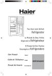
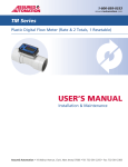
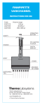
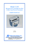
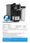
1
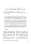
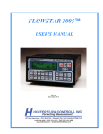
1-800-899-0553
assuredautomation.com
LM Series
Lube Oil Flow Meter
USER’S MANUAL
Installation & Maintenance
Assured Automation • 19 Walnut Avenue, Clark, New Jersey 07066 • Tel: 732-381-2255 • Fax: 732-381-2383
1-800-899-0553
assuredautomation.com
1. INTRODUCTION
The LM Series flow meter has incorporated the oval rotor principal
into its design. This has proven to be a highly reliable and highly
accurate method of measuring flow, providing exceptional
repeatability and high accuracy.
This meter is designed for inline use with engine oil & ATF up to a
maximum viscosity of SAE 140, diesel & water glycol mixtures with
a maximum water content of less than 50%.
2. INSTALLATION
Do not over tighten connections. Assured Automation
recommends, that if you are using your meter as an inline
application you should install a filter before the inlet of the meter.
3. OPERATION
3. To access the programs and settings, hold down the RESET
button for 5 seconds.
4. To scroll through the setting options press the DISP button.
Totals
1. 21 BATCH TOTAL = unit 21 (set units)
1.1 Press and hold down RESET for 5 seconds until “totL2”
appears.
1.2 Press RESET “unit 21” will appear.
1.3 Press and hold down RESET for 2 seconds (program will
appear).
1.4 Press RESET to scroll through the settings (ltr, gal, qrt) to
the desired units.
Display Button
1.5 Press and hold down RESET until “program” disappears to
accept setting.
Each press of the DISP button will allow you to scroll through the
meter options:
1.6 Press “RESET” for five seconds to return the meter to the
operating mode.
Resetable Batch Total
Resetable Accumulative Total
Non Resetable Accumulative Total
Flowrate
Reset Button
The RESET button allows you to reset the Batch Total or the
Resettable Acumulative Total to zero.
To reset either the Batch total or Resetable Acumulative total.
Press the DISP button to scroll to either the Batch or Resetable
total. When the required total is displayed. Press reset to zero
the totalizer.
Flowrate
This display option shows the flowrate of the fluid passing
through the meter.
Sleep Mode
If NO flow goes through the meter for 60 seconds the display
will go into sleep mode (blank). The display will automatically
wake if the buttons are pressed or flow occurs.
2. 22 BATCH TOTAL = dEC 22 (set decimal point)
2.1 Press and hold down RESET for 5 seconds until “totL2”
appears.
2.2 Press RESET twice “dEC 22” will appear.
2.3 Press and hold down RESET for 2 seconds (program will
appear).
2.4 Press RESET to set the decimal point to 1st, 2nd, 3rd or no
decimal place. (e.g 11111.1 = 1 decimal place)
2.5 Press and hold down RESET until “program” disappears to
accept setting.
2.6 Press RESET for five seconds to return the meter to the
operating mode.
3. 23 RESETABLE ACCUM TOTAL = unit 23 (set units)
3.1 Press and hold down RESET for 5 seconds until “totL2”
appears.
3.2 Press RESET three times “unit 23” will appear.
Electronic Module Programming Details
3.3 Press and hold down RESET for 2 seconds (program will
appear).
Note: As the decimal point does not float we recommend that a
maximum of 2 decimal places be used, see below for details.
3.4 Press RESET to scroll through the settings (ltr, gal, qrt) to
the desired units.
The electronic module has been set up as follows:
3.5 Press and hold down RESET until “program” disappears to
accept setting.
1. Ensure the meter is awake before trying to enter the
programming mode.
2. If the meter goes into sleep mode during programming, it will
automatically return to operating mode.
3.6 Press RESET for five seconds to return the meter to the
operating mode.
Contact us for the most recent product and technical information. Visit our website for more details: assuredautomation.com
2
1-800-899-0553
assuredautomation.com
4. 24 RESETABLE ACCUM TOTAL = dEC 24 (set decimal point)
4.1 Press and hold down RESET for 5 seconds until “totL2”
appears.
4.2 Press RESET four times “dEC 24” will appear.
4.3 Press and hold down RESET for 2 seconds (program will
appear).
4.4 Press RESET to set the decimal point to 1st, 2nd, 3rd or no
decimal place. (e.g 11111.1 = 1 decimal place)
4.5 Press and hold down RESET until “program” disappears to
accept setting.
4.6 Press RESET for five seconds to return the meter to the
operating mode.
5. 25 NON-RESET ACCUM TOTAL = unit 25 (set units)
5.1 Press and hold down RESET for 5 seconds until “totL2”
appears.
7.4 To change the ‘K’ factor, press RESET (digit will flash), to
change digit press RESET.
Press DISP to scroll to the next number. Press RESET to
change the value
To change the decimal point, press DISP until it is in the
required position. Press RESET to set the decimal point.
7.5 Press and hold down RESET until “program” disappears to
accept setting.
7.6 Press RESET for five seconds to return the meter to the
operating mode.
Flow Rate
1. 31 UNITS = unit 31 (set units)
1.1 Press and hold down RESET for 5 seconds until “totL2”
appears.
1.2 Press the DISP button once to reach “rAtE 3”.
5.2 Press RESET five times “unit 25” will appear.
1.3 Press RESET “unit 31” will appear.
5.3 Press and hold down RESET for 2 seconds (program will
appear).
1.4 Press and hold down RESET for 2 seconds (program will
appear).
5.4 Press RESET to scroll through the settings (ltr, gal, qrt) to
the desired units.
1.5 Press RESET to scroll through the settings (ltr, gal, qrt) to
the desired units.
5.5 Press and hold down RESET until “program” disappears to
accept setting.
1.6 Press and hold down RESET until “program” disappears to
accept setting.
5.6 Press RESET for five seconds to return the meter to the
operating mode.
1.7 Press “RESET” for five seconds to return the meter to the
operating mode.
6. 26 NON-RESET ACCUM TOTAL = dEC 26 (set decimal point)
2. 32 DECIMAL POINT = dEC 32 (decimal point setting)
6.1 Press and hold down RESET for 5 seconds until “totL2”
appears.
2.1 Press and hold down RESET for 5 seconds until “totL2”
appears.
6.2 Press RESET six times “dEC 26” will appear.
2.2 Press the DISP button once to reach “rAtE 3”.
6.3 Press and hold down RESET for 2 seconds (program will
appear).
2.3 Press RESET twice “dEC 32” will appear.
6.4 Press RESET to set the decimal point to 1st, 2nd, 3rd or no
decimal place. (e.g 11111.1 = 1 decimal place)
6.5 Press and hold down RESET until “program” disappears to
accept setting.
6.6 Press RESET for five seconds to return the meter to the
operating mode.
7. 27 “K” FACTOR = kFac 27 (normal setting is 112.00 pulses)
7.1 Press and hold down RESET for 5 seconds until “totL2”
appears.
7.2 Press RESET seven times “kFac 27” will appear.
7.3 Press and hold down RESET for 2 seconds (program will
appear).
2.4 Press and hold down RESET for 2 seconds (program will
appear).
2.5 Press RESET to set the decimal point to 1st, 2nd, 3rd or no
decimal place. (e.g 11111.1 = 1 decimal place)
2.6 Press and hold down RESET until “program” disappears to
accept setting.
2.7 Press RESET for five seconds to return the meter to the
operating mode.
3. 33 TIME = tiME 33 (rate time base)
3.1 Press and hold down RESET for 5 seconds until “totL2”
appears.
3.2 Press the DISP button once to reach “rAtE 3”.
Contact us for the most recent product and technical information. Visit our website for more details: assuredautomation.com
3
1-800-899-0553
assuredautomation.com
3.4 Press RESET three times “tiME 33” will appear.
1.2 Press the DISP button twice to reach “diSP 4”.
3.5 Press and hold down RESET for 2 seconds (program will
appear).
1.3 Press RESET “SLP 41” will appear.
3.6 Press RESET to set time base (seconds, minutes, hours).
3.7 Press and hold down RESET until “program” disappears to
accept setting.
3.8 Press RESET for five seconds to return the meter to the
operating mode.
4. 34 NUMBER OF PULSES = nuM 34 (number of pulses used to
calculate flowrate)
Note: When there is fluctuating flowrate present increasing the
number will give a more accurate flowrate reading (number
range is 0 to 299).
1.4 Press and hold down RESET for 2 seconds (program will
appear).
1.5 Press RESET to select sleep setting (no sleep, sleep)
1.6 Press and hold down RESET until “program” disappears to
accept setting.
1.7 Press “RESET” for five seconds to return the meter to the
operating mode.
2. 42 UNIT = unit 42 (set default display)
Note: The display will reset to the default units after a time
which is set in “time 43”. If no units are set, the display will
remain as selected
4.1 Press and hold down RESET for 5 seconds until “totL2”
appears.
2.1 Press and hold down RESET for 5 seconds until “totL2”
appears.
4.2 Press the DISP button once to reach “rAtE 3”.
2.2 Press the DISP button twice to reach “diSP 4”.
4.3 Press RESET four times “nuM 34” will appear.
2.3 Press RESET twice “unit 42” will appear.
4.4 Press and hold down RESET for 2 seconds ( program will
appear and the digit will flash). To change press RESET.
2.4 Press and hold down RESET for 2 seconds (program will
appear).
4.5 Press DISP to go to the next digit. To change press RESET.
2.5 Press RESET to select required display (batch, reset total,
total, rate, blank).
4.6 Press and hold down RESET until “program” disappears to
accept setting.
4.7 Press RESET for five seconds to return the meter to the
operating mode.
5. 35 FLOW = Cut 35 (set minumum measurable flowrate)
This value is the maximum time (sec) to measure the number
of pulses set in nuM 34.
5.1 Press and hold down RESET for 5 seconds until “totL2”
appears.
5.2 Press the DISP button once to reach “rAtE 3”.
5.3 Press RESET five times “Cut 35” will appear.
5.4 Press and hold down RESET for 2 seconds ( program will
appear and the digit will flash). To change press RESET.
5.5 Press DISP to go to the next digit. To change press RESET.
Note: Total number is 999.9.
5.6 Press and hold down RESET until “program” disappears to
accept setting.
5.7 Press RESET for five seconds to return the meter to the
operating mode.
Display
1. 41 SLEEP MODE = SLP 41 (set sleep mode)
1.1 Press and hold down RESET for 5 seconds until “totL2”
appears.
2.6 Press and hold down RESET until “program” disappears to
accept setting.
2.7 Press RESET for five seconds to return the meter to the
operating mode.
3. 43 TIME = tiME 43 (time to revert to default display)
3.1 Press and hold down RESET for 5 seconds until “totL2”
appears.
3.2 Press the DISP button twice to reach “diSP 4”.
3.4 Press RESET three times “tiME 43” will appear.
3.5 Press and hold down RESET for 2 seconds (program will
appear).
3.6 Press RESET to select default time (5 to 20 seconds).
3.7 Press and hold down RESET until “program” disappears to
accept setting.
3.8 Press RESET for five seconds to return the meter to the
operating mode.
Calibration
Note: Provides calibration adjustment up to +/- 5% of reading.
You will need to calculate the percentage adjustment you require.
If the meter is reading over you will need to enter a minus figure.
If the meter is reading under you will need to enter a plus figure.
Contact us for the most recent product and technical information. Visit our website for more details: assuredautomation.com
4
1-800-899-0553
assuredautomation.com
1. Reset the batch reading to zero.
Diagnostics
2. Dispence at least 5 liters, using a constant flow rate, into a
graduated calibrated container.
1. 71 DIAGNOSTICS = dIA 7 (diagnostic mode)
3. Take the reading from the meter.
4. Calculate the % error as follows: % error = ((container
volume - meter volume) ÷ container volume) x 100.
5. Enter the % error into the meter as calculated, if the value is
negative enter a negative number.
6. 51 CALIBRATION = CALI 51 (adjust calibration ±5%)
1.1 Press and hold down RESET for 5 seconds until “totL2”
appears.
1.2 Press the DISP button five times to reach “dIA 7”.
1.3 Press and hold down RESET for 2 seconds (Program will
appear then all the segments should be displayed).
1.4 Press the DISP button “diSP” (to check that the display
button is working properly).
6.1 Press and hold down RESET for 5 seconds until “totL2”
appears.
1.5 Press the RESET button “RESEt” (to check that the reset
button is working properly).
6.2 Press the DISP button three times to reach “CALI 5”.
1.6 Press and hold down RESET for 2 seconds (program will
disappear (check the condition of the reed switch).
6.3 Press RESET “CALI 51” will appear.
6.4 Press and hold down RESET for 2 seconds (program will
appear).
6.5 Press RESET to change number.
Press DISP to change the decimal point position, or go to
the next number.
Press the RESET button to set the negative value.
6.6 Press and hold down RESET until “program” disappears to
accept setting.
6.7 Press RESET for five seconds to return the meter to the
operating mode.
Configuration
1. 61 CONFIGURATION = CONF 6 (configuration details)
1.1 Press and hold down RESET for 5 seconds until “totL2”
appears.
1.2 Press the DISP button four times to reach “CONF 6”.
1.3 Press RESET “MOD” plus model number will appear.
1.4 Press RESET “REL” plus hardware release number will
appear.
1.5 Press RESET the screen will flash between “SOFT” and the
software release number (at 2 second intervals).
1.6 Press RESET the screen will flash between “SEr” and the
6 figure serial number (at 2 second intervals).
1.7 Press RESET “MAN” plus manufacturer number.
1.8 Press RESET the screen will flash between “CONFIG” and
the configuration number (at 2 second intervals).
1.9 Press RESET for five seconds to return the meter to the
operating mode.
Note: The display shows (Hxx rYY) when fluid flows
through the meter. YY is the sensitivity of the reed switch.
The condition of the reed switch can only be checked
when there is liquid flowing through the meter. The reed
switch should be reading between 50 to 80.
1.7 Press RESET for five seconds to return the meter to the
operating mode.
5. MAINTENANCE
Battery Replacement
All data will be saved when
the batteries are removed.
Fig. 1
Note: Replace the batteries as
soon as the battery indicator
on the LCD is displayed. Only
use Alkaline batteries.
1. Remove the plastic protector
shroud (see Fig. 1) from the
meter body.
2. Remove the battery cover.
3. Replace the two AAA Alkaline batteries. Refer to the front of
the meter for correct battery orientation.
4. Replace the battery cover and re-fit the plastic shroud.
Meter Disassembly
Caution: Ensure the fluid supply to the meter is disconnected
and the line pressure is released before disassembly.
1. Remove the eight philips head screws from the meter cover.
2. Remove the meter cover and o-ring.
3. Remove both rotors.
Contact us for the most recent product and technical information. Visit our website for more details: assuredautomation.com
5
1-800-899-0553
assuredautomation.com
4. Clean and inspect all parts. Replace any suspect, worn or
damaged components.
6. TROUBLE SHOOTING
Meter Reassembly
1. Cause: Dirt particles jamming the rotors.
Remedy: Remove rotors and remove any dirt or contamination.
Note: Ensure the rotor with the
magnets is assembled on the
same side as the batteries. The
magnets in the rotor must face
towards the electronic display
Fig. 2
1. Replace both rotors so as
they are at 90º to each
other (see Fig. 2). Check the
rotor rotation by turning either of the rotors. If the rotors are
not in mesh correctly or do not rotate freely remove one of the
rotors and replace it correctly at 90º to the other rotor. Recheck
the operation of the rotors.
Problem: No fluid passing through the meter.
Problem: The meter is not registering fluid output.
1. Cause: Flat battery.
Remedy: Replace battery.
2. Cause: No signal from rotor the magnets.
Remedy: Check magnets and replace rotors if required.
3. Cause: Damaged computer (reed switch unit).
Remedy: Replace meter.
Problem: Meter not accurate.
2. Lightly grease the o-ring and place it on the meter body.
1. Cause: Flow rate outside recommended flow rate.
Remedy: Adjust flow rate.
3. Clean the meter cover plate and place it on the body. Take care
not to damage the o-ring.
2. Cause: "K" factor incorrect.
Remedy: Reset "K" factor to factory setting (112.00 pulses).
4. Install the eight screws and tighten in a diagonal pattern to
1 nm (0.73 ft/lb). Visual check that the cap has been pulled
down evenly.
5. Test the meter by turning the rotors with a finger or by applying
low air pressure (no more than a good breath) to the inlet port
of the meter. This will confirm the meter is operating correctly.
Parts Diagram
Meter Body
Rotors
O-ring Seal
Meter Cover Plate
Eight (8) philips head screws
Contact us for the most recent product and technical information. Visit our website for more details: assuredautomation.com
6