1
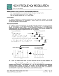
1-800-899-0553
assuredautomation.com
Economy Series Fuel Meter
Economical Digital Flow Meter (Totalizer Only with Reset)
USER’S MANUAL
Installation & Maintenance
Assured Automation • 19 Walnut Avenue, Clark, New Jersey 07066 • Tel: 732-381-2255 • Fax: 732-381-2383
1-800-899-0553
assuredautomation.com
1. IMPORTANT NOTICE
5. MAINTENANCE
Use this meter for gasoline, diesel fuel and kerosene only. Do not
use to meter water or chemicals. Do not use for measuring fuel or
other liquids into aircraft.
Proper handling and care will extend the life and service of
the meter.
This meter is not legal for trade applications.
The meter is very sensitive to electrical “noise” and may not
operate correctly if located near some electrical equipment.
2. INSTALLATION
Install the meter at the end of the fuel hose adjacent to the
nozzle. This meter may also be installed in-line either horizontally
or vertically. Install as follows:
1. Remove nozzle from hose.
2. Wrap all connections with 3 to 4 wraps of pipe tape. Ensure
the tape does not intrude into the flow path.
3. Attach meter to hose with arrow on outlet port pointed in the
direction of flow.
4. Attach nozzle to meter. If necessary, use the enclosed
3/4-inch fitting.
Turbine Rotor
The meter is virtually maintenance-free. However, it is important
the rotor moves freely. Keep the meter clean and free of
contaminants.
If the rotor does not turn freely, apply a penetrating lubricant on
the rotor, shaft, and bearings. Remove any debris or deposits from
the rotor using a soft brush or small probe. Be careful not to
damage the turbine rotor or supports.
Caution: Blowing compressed air through the turbine
assembly could damage the rotor.
Battery Replacement
The meter is powered by two AAA alkaline batteries which may be
replaced while the meter is installed. When batteries are removed
or lose power, the batch and cumulative totals reset to zero but
the factory calibration is retained.
5. With a wrench, tighten the meter at the housing ends.
If the display becomes dim or blank, replace the batteries as
follows:
2. OPERATION
1. Remove the four Phillips-head screws from the face of the
meter and lift the faceplate from the turbine.
Batch and Cumulative Totals
The meter maintains two totals. The batch total may be reset to
measure flow during a single use. The cumulative total provides
continuous measurement and may not be manually reset. The
batch total is labeled as TTL1. The cumulative total is labeled TTL2.
2. Remove the old batteries and clean any corrosion from the
terminals.
When the cumulative total reaches a maximum reading of 9999, it
will automatically reset to zero.
4. When the batteries are replaced, the faceplate will power ON.
Check the display to ensure normal functions have resumed
before assembling again.
Press the DISPLAY button briefly to switch between the batch and
cumulative total.
Activate the Meter
3. Install new batteries. Make sure the positive post is in the
correct position.
5. Reseat batteries, if necessary, and position the faceplate on the
turbine housing. To avoid moisture damage, make sure the
O-ring is fully seated. Tighten the four screws on the faceplate.
Turn the meter ON by starting water flow or briefly pressing the
DISPLAY button. The meter will display the batch or cumulative
total from last use.
Press DISPLAY briefly to display the batch total. Hold the DISPLAY
button down for three seconds to reset the batch total to zero.
The meter is programmed to turn off automatically if not used for
about one minute.
3. CALIBRATION
This meter has a permanent factory calibration for measuring
gasoline, diesel fuel or kerosene. If installed and used correctly,
inaccuracies of no greater than ±5% will be obtained.
Contact us for the most recent product and technical information. Visit our website for more details: assuredautomation.com
2