1
Version 1.1
ArcDot Power
Table of contents
1. Important safety instructions......................................................................................... 3
1. Consignes de sécurité importantes.............................................................................. 4
2. Operating determinations............................................................................................... 4
3.Description of the ArcDot Power.................................................................................... 5
4.Installation........................................................................................................................ 5
4.1.Connection to the mains:............................................................................................ 5
4.2.Mounting the ArcDot Power........................................................................................ 6
4.3. Connecting ArcDotPower and ArcDots...................................................................... 6
5.ArcDot Power - Control menu map................................................................................. 8
6.ArcDot Power - DMX protocol,........................................................................................ 9
7.Control board.................................................................................................................. 10
7.1 Addressing the ArcDot Power .................................................................................. 10
7.2 ArcDots .................................................................................................................... 10
7.3 Personality................................................................................................................ 11
7.4 Fixture information.................................................................................................... 11
7.5 Test........................................................................................................................... 12
7.6 Special functions....................................................................................................... 12
8.Technical Specifications:.............................................................................................. 14
9. Replacing the fuse ....................................................................................................... 15
CAUTION!
Unplug mains lead before opening the housing!
FOR YOUR OWN SAFETY, PLEASE READ THIS USER MANUAL CAREFULLY
BEFORE YOU INITIAL START - UP!
ATTENTION!
Débrancher l’appareil avant d'ouvrir le boîtier!
POUR VOTRE SÉCURITÉ, LISEZ ATTENTIVEMENT CETTE NOTICE AVANT LA PREMIERE UTILISATION
1. Important safety instructions
Every person involved with installation and maintenance of this product has to:
- be qualilfied
- follow the instructions and heed all warnings in this manual
CAUTION!
Be careful with your operations. With a high voltage you can suffer
a dangerous electric shock when touching the wires inside the unit!
This product has left our premises in absolutely perfect condition. In order to maintain this condition and to
ensure a safe operation, it is absolutely necessary for the user to follow the safety instructions and warning
notes written in this manual.
WARNING
To prevent injury, this apparatus must be securely installed in accordance with the
installation instructions.”
Do not block any ventilation openings. Install in accordance with the manufacturer’s instructions.
Do not install near any heat sources such as radiators, heat registers, stoves, or other apparatus (including
amplifiers) that produce heat.
Do not use this apparatus near water. Clean only with dry cloth.
MAINS plug or an appliance coupler is used as the disconnect device, the disconnect device shall remain
readily operable.
Only use attachments/accessories specified by the manufacturer.
Protect the power cord from being walked on or pinched particularly at plugs, convenience receptacles, and
the point where they exit from the apparatus.
Refer all servicing to qualified service personnel. Servicing is required when the apparatus has been damaged
in any way, such as power-supply cord or plug is damaged, liquid has been spilled or objects have fallen into
the apparatus, the apparatus has been exposed to rain or moisture, does not operate normally, or has been
dropped.
Use a source of AC power that complies with local building and electrical rules.AC power has to have both
overload and short circuit protection.
This device falls under protection class I.Therefore the ArcDotPower has to be connected to a mains socket outlet with a protective earthing connection!
1. Consignes de sécurité importantes
Toute personne impliquée dans l'installation et la maintenance de ce produit doit:
- Être suffisamment qualifié
- Suivre les instructions de ce manuel
ATTENTION!
Soyez prudent avec vos manipulations. Avec une haute tension, vous risquez un
choc électrique en touchant les fils à l'intérieur de l'appareil!
Ce produit a quitté nos ateliers dans un état irréprochable. Afin de maintenir cet état et pour assurer un bon
fonctionnement, il est absolument nécessaire de suivre les consignes de sécurité et les notes contenues dans
ce manuel.
AVERTISSEMENT
Pour éviter toute blessure, cet appareil doit être solidement fixé à en conformité
avec les instructions d'installation. "
Ne pas bloquer les ouvertures de ventilation. Installer conformément aux instructions du fabricant.
Ne pas installer près de sources de chaleur telles que radiateurs, ou autres appareils (y compris les amplificateurs) produisant de la chaleur.
Ne pas utiliser cet appareil près de l'eau. Nettoyer avec un chiffon sec.
Une prise de branchement ou un coupleur est utilisé comme dispositif de déconnexion, ce dispositif doit rester
facilement accessible.
N'utilisez que des accessoires spécifiés par le fabricant.
Protégez le cordon d'alimentation du piétinement ou pincement, particulièrement au niveau des fiches, des
prises, et le point où ils sortent de l'appareil
Confiez toute réparation à un personnel qualifié. Une réparation est nécessaire lorsque l'appareil a été endommagé de quelque façon que ce soit. cordon d'alimentation, fiche est endommagé, liquide renversé a l interieur,
ou des objets sont tombés dans l'appareil, l'appareil a été exposé à la pluie ou à l'humidité, ne fonctionne pas
normalement , ou s'il est tombé.
Utilisez une source de courant alternatif qui est conforme a l’endroit ou vous vous trouvez. La source alternative
doit avoir à la fois une protection de surcharge et de court-circuit.
Ce dispositif relève de la classe de protection I. Par conséquent, la ArcDotPower
doit être connecté à une prise électrique reliée à la terre!
2. Operating determinations
This product was designed for indoor use only.
If the unit has been exposed to drastic temperature fluctuation (e.g. after transportation), do not switch it on
immediately. The arising condensation water might damage your unit. Leave the unit switched off until it has
reached room temperature.
Avoid brute force when installing or operating the unit.
When choosing the installation-spot, please make sure that the unit is not exposed to extreme heat, moisture
or dust.
Only operate the unit after having checked that the housing is firmly closed and all screws are tightly fastened.
The maximum ambient temperature 40° C must never be exceeded.
Operate the unit only after having familiarized with its functions. Do not permit operation by persons not qualified for operating the unit. Most damages are the result of unprofessional operation!
Please use the original packaging if the product is to be transported.
Please consider that unauthorized modifications on the unit are forbidden due to safety reasons!
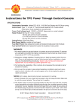
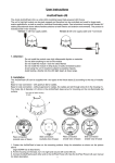
3.Description of the ArcDot Power
1 - Control board
2 - Power cord
3 - Ethernet
4 - DMX Output
5 - DMX Input
6 - ArcDot output 4
7 - ArcDot output 3
8 - ArcDot output 2
9 - ArcDot output 1
4.Installation
CAUTION!
These servicing instructions are for use by qualified service personnel only. To
reduce the risk of electric shock do not perform any servicing other than that contained in the operating instructions unless you are qualified to do so.
4.1.Connection to the mains:
The ArcDot Power is equipped with auto-switching power supply that automatically adjusts to any 50/60Hz AC
power source from 100-240 Volts.
The fixture is equipped the cord & plug QP 02 but you can use the following plugs: P620,24W47,14W49,24W
49,26W81,HBL4720C,HBL2311, HBL2321,HBL2811 and the cords SJT or 22326.
Cord plug connection:
Cable (EU)
Cable (US)
Pin
International
Brown
Black
Live
L
Liht blue
White
Neutral
N
Yellow/Green
Green
Earth
This device falls under protection class I.Therefore the ArcDot Power has to be connected to a mains socket outlet with a protective earthing connection.
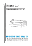
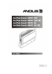
4.2.Mounting the ArcDot Power
The ArcDot Power should be be placed on a non-flammable flat surface in any orientation and fixed by the four
screws.There are four mounting holes of a diameter of 5 mm in housing of the driver. Ensure that instalation
place is enough ventilated.
Screws
Flat surface
Mounting holes
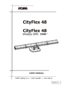
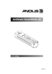
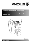
4.3. Connecting ArcDotPower and ArcDots
Connect ArcDots to the LED outputs of the ArcDotPower, typically 25 ArcDots per output (max. 35 ArcDots).
Max. number of all LED modules connected to the ArcDotPower is 100. The ArcDots can be interconnected
directly or by using T- connectors - see the picture below. If you use Artnet for control of the ArcDot Power,
you can connect ArcDots to all LED outputs 1-4.
For larger installation (more than 25 ArcDots), the ArcDotPower should be connected to the Robe Media Server
which allows automatic pixel mapping and full control of the ArcDots modules. Without Robe Media Server, you
have to perform pixel mapping manually using the menu "dotS".
To connect ArcDots
1. Disconnect ArcDotPower from mains.
2. Connect ArcDots to the ArcDotPower. Connect active terminators to each ArcDots line.
3. Connect ArcDotPower to mains
4. Run procedures Pixels checking (Find) and Pixel sorting (Sort) from menu ArcDot (dotS)
5. Save found values with option Store (Stor)
6. Disconnect the ArcDotPower from mains and replace active terminators by passive terminators*.
7. Connect the ArcDotPower to mains and to the Robe Media Server.
* Active terminators can remain permanent connected if there is place for them (they are biggers than passive
ones).
The minimum cable length of 0.3m
between two T-connectors has to
be kept in case that the pixel sorting is executed manually from the
ArcDotPower menu.
This rule does not need to be kept
if the Robe Media Server is used
for pixel sorting
Max. total length of cable depends
on the number of ArcDots connected to the ArcDotPower (100 m
@ 25 ArcDots, 65 m @ 35 ArcDots
per output.
Every ArcDot line has to
be terminated with the
passive terminator!
If the line between ArcDots is disconected, the ArcDots behind point of interrupt will not work. Before restoring
connection betwen ArcDots, switch off the ArcDotPower.
In case that some ArcDot is changed, the same address as had original ArcDot is assigned to it by ArcDotPower. It is very important to save ArcDots configuration at every change of the ArcDot.(Menu "Dots"
-> "Store"),
Max. cable length between ArcDotPower and the last connected ArcDot module should not be exceeded:
100m @ 25 ArcDots per LED output or 65 m @ 35 ArcDots per LED output. Only one ArcDot module can
be connected to the T-connector.
Note: If DMX is used for control of the ArcDot Power, the LED outputs 1-3 may be used only (LED output
load is the same as in case of control by Artnet - typically 25 LED modules, max 35 LED modules and 100
modules max. load of ArcDotPower).
Every ArcDot line has to be terminated with the passive terminator!
The Robe Media Server allows to choose two modes of ArcDots connection: Fixed-wiring mode and Picture
mode. For detailed description see the user manual of the Robin Media Server.
5.ArcDot Power - Control menu map
Default settings=Bold print
A001
dM. Ad.
IP.Ad
dEF.A
SEt
CUS.A.
IP.A1 (0-255)
:
IP.A4 (0-255)
SEt
nEt M.
nE.M.1 (0-255)
:
nE.M.4 (0-255)
dotS
FInd
Sort
F.tin (0-255)
CurV (0-255)
Stor.
PErS
Art.U. (0-255)
dISP.
turn
d.On
d.Int (30, 50, 80,100)
dM.In.
DMH
Eth
dEF.S.
InFo
S.VEr.
IP.Ad.
rdM.U.
MAC.A
dotS
SPEC
UPd
d.1
:
MA.In
IP.A1
:
IP.A4
rdM.1
:
rdM.3
MAC.1
:
MAC.3
d.MiS
nEU.d.
(no, YES)
6.ArcDot Power - DMX protocol,
version 1.0
Channel
Value
Function
Type of control
ArcDot 1
1
2
3
0-255
Red
Red LED saturation control (0-100%)
proportional
0-255
Green
Green LED saturation control (0-100%)
proportional
0-255
Blue
Blue LED saturation control (0-100%)
proportional
0-255
Red
Red LED saturation control (0-100%)
proportional
0-255
Green
Green LED saturation control (0-100%)
proportional
0-255
Blue
Blue LED saturation control (0-100%)
proportional
ArcDot 2
4
5
6
ArcDot 3
7
8
9
0-255
Red
Red LED saturation control (0-100%)
proportional
0-255
Green
Green LED saturation control (0-100%)
proportional
0-255
Blue
Blue LED saturation control (0-100%)
proportional
:
:
:
:
:
:
:
ArcDot 100
298
299
300
0-255
Red
Red LED saturation control (0-100%)
proportional
0-255
Green
Green LED saturation control (0-100%)
proportional
0-255
Blue
Blue LED saturation control (0-100%)
proportional
7.Control board
The control panel situated on the top cover of the ArcDot Power allows fixture addressing and set the driver´s
behaviour.
Control elements:
[ENTER] button- enters menu,confirms adjusted values and leaves menu.
,
[UP] button and[DOWN] button- moves between menu items on the the same level, sets values.
[ESCAPE] button- leaves the menu without saving value.
7.1 Addressing the ArcDot Power
M.Ad. - DMX address. Select this menu item to set desired DMX address.l
IP.Ad. - IP address. Select this menu item to set desired IP address. IP address is the Internet protocol
address.The IP uniquely identifies any node (fixture) on a network. There cannot be 2 fixtures with
the same IP address on the network!
dEF.A. - Default IP address. This address is derived from fixture´s MAC address and
cannot be changed. Confirm item "SEt" if you want to set default IP address.
CUS.A. - Custom IP address. IP address consists of four decimal numbers, each ranging
from 0 to 255, separated by dots, e.g., 172.16.254.1. Each part represents a group of 8 bits
(octet) of the address.
The following items "IP.A1", "IP.A2", "IP.A3", "IP.A4" allow to set each part (number) of
the address. After setting desired IP address, confirm item "SEt" to save set address.
nEt.M. - Net mask. Select this menu item to set desired Net mask. A Net mask is a 32-bit mask used to divide
an IP address into subnets and specify the networks available hosts.
The following items "nE.M.1", "nE.M.2", " nE.M.3", " nE.M.4" serve for seting of each part (number) of the
net mask.
7.2 ArcDots
Use this menu to prepare ArcDots for operation in desired matrix.
FInd - Pixels checking. This function checks all pixels connected to the fixture and
the message “donE” is displayed after finishing the procedure.
NOTE: Active terminator has to be connected to the last ArcDot of each ArcDots line.
Sort - Pixels sorting. This function starts auto-sorting of each conncted ArcDot modules. After sorting, dots
will have order Red, Green, Blue.
NOTE: Active terminator has to be connected to the last ArcDot of each ArcDots line.
M.F.ti. --- Max. fade time. Select this menu item to set a desired max. fade time (0-25.5 sec.). This adjusted
fade time influences fade of RGB and dimmer during DMX operation:
10
If time between two receiving DMX values is > than fade time set in the item M.F.ti., the entire adjusted fade
time will be used.
If time between two receiving DMX values is < than fade time set in the item M.F.ti., the adjusted fade time will
be reduced to fill entire time between the two receiving DMX values.
e.g. M.F.ti.=2sec. and fixture has received Red=0 DMX, after 5 seconds will receive Red=255 DMX. It means,
that red will go to full intensity during 2 seconds.
M.F.ti.=8 sec. and fixture has received Red=0 DMX, after 5 seconds will receive Red=255 DMX. It means,
that red will go to full intensity during 5 seconds. (Max, fade time is reduced from 8 sec. to 5 sec.).
CurV. --- Saturation curve. This menu item allows you to select desired running of colour saturation. You can
select 255 colour saturation runnings in all. The value 0 corresponds linear curve, the value 128 corresponds
exponential curve with index 1.9 and last value 255 corresponds exponential curve with index 2.6.
Stor. --- Store. Select this function to save all adjustem items in the menu "dotS"
7.3 Personality
Use this menu to modify the ArcDotPower operating behavior.
Art.U. - ArtNet Universe. Select the menu item to set ArtNet universe. Art-Net is a proprietary protocol for
transmitting DMX512 (with RDM) over UDP/IP. Up to sixteen DMX512 universes can be accessed through one
IP subnet. The Universe is a single DMX 512 frame of 512 channels.
dISP. - Display adjusting. This menu allows you to change the display settings.
turn - Select this item to turn the display by 180°.
d.On - This menu item allows you to keep the display on or to turn it off automatically 2 minutes
after last pressing any button on the control panel.
d.Int. - Select this menu item to adjust the display intensity (30, 50, 80, 100-max.).
dM.In. - DMX input selection. This menu allows to choose desired DMX data input:
dMH - DMX. If this input is selected, only LED outputs 1-3 are active.
Eth - Ethernet. If this input is selected, all LED outputs (1-4) are active.
dEF.S. - Default setting. Select this option to reset fixture personalities and setting to the default (factory).
values.
7.4 Fixture information
Use this menu to read useful information about the fixture.
S.VEr. - Software version. Select this menu item to read software versions.
11
d.1-d.100 - Dot version. The items show software version of each ArcDot.
MA. In - Driver version. The item shows software version of the ArcDotPover.
IP.Ad. - IP address . Select this menu item to read individul parts ( "IP.A1", "IP.A2", "IP.A3", "IP.A4") of the
current IP address.
rdM.U. - RDM Universe ID . Select this menu item to read individul parts ( "rdM.1", "rdM.2", "rdM.3") of the
RDM Universe ID.
MAC.A. - MAC Address. Select this menu item to read individul parts ( "MAC.1", "MAC.2", "MAC.3") of the
MAC address.
dotS. - ArcDots information. Select this menu item to read information about ArcDots
d.MiS - Missing ArcDot. The item shows the number of ArcDots which were not detected
by the Pixel checking procedure ("Find") .
nEU.d - New ArcDot. The item shows the number of recently connected ArcDots.
7.5 Test
The menu starts program sequense over all connected ArcDots in order red, green, blue. Before running this
Test program, the "Pixel checking" and Pixel sorting" procedures from menu PErS have tu be performed.
7.6 Special functions
Use this menu for special services.
uPd. --- Software update - Using this function you can update software in the fixture via PC and USB (serial
link).
The following are required in order to update software:
- PC running Windows 95/98/2000/XP/7 or Linux
- DMX Software Uploader
- Flash cable RS232/DMX (No.13050624) or Robe Universal Interface
Note1. Software update should execute a qualified person.If you lack qualification, do not try the update
yourself and ask for help your ANOLIS distributor.
Note 2. IP address, and settings in menu " PErS" will be set to their default values.
To update software in the fixture:
1.Installation of DMX Software Uploader:
1.DMX Software Uploader program is available from the ANOLIS web site at WWW.anolis.cz.
2.Make a new directory ( e.g. ANOLIS_Uploader) on your hard disk and download the software to it.
3.Unpack the program from the archives. Program file has name:DSU_name of corresponding
fixture_SoftwareID.SoftwareID describes the versions of fixture software included in DMX Software
Uploader. Higher number means later software versions.
2.Fixture software updating:
1.Determine which of your COM port is available on your PC and connect it with to the DMX input
of the fixture using the Flash cable. Do not extend this cable! Disconnect the fixture from the
other fixtures in DMX chain! Turn on the computer and the fixture.
2.Switch the fixture to the update mode by selecting the option Software update in menu Special
Functions on the fixture control panel:SPEC-->UPd-->yES.(From this option you cannot return
back to the main menu. If you do not want to continue in software update, you have to switch off
and on the fixture to leave this option!)
3.It is recommended that you exit all programs before running the Software Uploader.
4.Start the Software Uploader program. Select desired COM and then click Connect button.
If the conection is OK, click Start Uploading button to start uploading. It will take several minutes to
perform software update.All processors will be updated (including processors with the same software version).
If you wish to update only later versions of processors, enable the Incremental Update check box.
12
Avoid interrupting the process. Update status is being displayed in the list window.
When the update is finished, the line with the text “The fixture is successfuly updated‘ will appear
in this window and the fixture will reset with the new software.
Note: In the case of interruption of the upload process (e.g. power cut), the fixture remains in the update mode
and you have to repeat the software update again.
13
8.Technical Specifications:
Power supply
Input Voltage: 100-240 V AC, 50-60 Hz
Fuse:T 8 A
Max.Pover Consumption: 640W
Control and programming
Protocols: USITT DMX-512, Artnet
Display: 4 digit LED
4 control buttons
DMX channels
Dot 1:
1=R1 Dot 2: 4=R2
2=G1
5=G2
3=B1
6=B2
........................................................Dot 100: 298=R100
........................................................
299=G100
........................................................
300=B100
Output
Max.Output Voltage:48V DC
Max.Output power: 583 W
ArcDot outputs: 4
Max.load per ArcDot output: 35 ArcDots (typically 25 ArcDots)
Total max.load per ArcDot Power: 100 ArcDots
Maximum cable length between ArcDot output and the last connected ArcDot module
100 m (25 ArcDots per output)
65 m (35 ArcDots per output)
Total heat dissipation
max. 1980 BTU/hr
Connections
DMX 512: 3-pin male/female XLR
Output
Input
1 Shield
2 Signal (-)
3 Signal (+)
ArtNet: RJ45
1
2
3
4
TD+ TD-
RX+
Not connected
5
6
7
8
Not connected
RXNot connected
Not connected
LED output: Chogori CGRBB-03RFFS-SC8001 (female)
1 GND
2 +48V
3 Data
Connection ArcDot-ArcDotPower
Cable : Li9Y11Y, 2xAWG16+1xAWG 20
Connectors: Chogori CGRBB-03BMMA-SL8001 (male) Chogori CGRBB-03BFFA-SL8001 (female)
1 GND (blue wire)
2 +48V (red wire)
3 Data (orange wire)
14
1 GND (blue wire)
2 +48V (red wire)
3 Data (orange wire)
Operating temperature
-10°C/+40°C
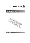
Dimensions(mm)
Weight
4.7 kg
Total heat dissipation
2180 BTU/h (calculated)
Optional accessories
Connection cable ArcDot-ArcDotPower
(P/N 1006 2330) Active Terminator for ArcDot
(P/N 1006 2331 Passive Terminator for ArcDot
9. Replacing the fuse
1.Before replacing the fuse, unplug mains lead!
2.Unscrew the fuse holder on the rear side of the ArcDot Power with a fitting screwdriver from the housing
(anti-clockwise).
3.Remove the old fuse from the fuse holder.
4.Install the new fuse in the fuse holder.
5.Replace the fuse holder in the housing and fix it.
Specifications are subject to change without notice.
February 25, 2013
15
16