1
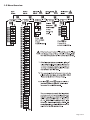
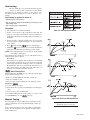
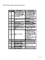
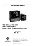
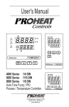
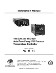
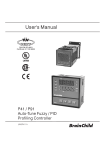
Visionary Solutions for Industry
®
Temperature Controllers & Sensors
◆
®
Since 1972 —
Heating Elements
◆
ISO 9001 Certified
Process Heating Systems
®
Instructions for TPC Power Through Control Console
SPECIFICATIONS
Temperature Controller: Model TEC-9100, 1/16 DIN Dual Display with PID Auto-tuning
Sensor Input: Type “J” or type “K” thermocouple dependent on model ordered
(Alternative inputs available for special order)
Power Cord/voltage Input: 120VAC or 240VAC (dependent on model ordered)
Heater Output: 8A max for 1-zone consoles
4A max per zone for 2-zone consoles
2.7A max per zone for 3-zone consoles
2A max per zone for 4-zone consoles
Output Device: Solid State Relay
Main Power Switch: Located on front panel
Fuse Main Power: See replacement parts list (located inside power inlet module)
Fuse Control Power: See replacement parts list (located on back panel)
WARNINGS
1. Air vents located on top and bottom of console must not be blocked! To prevent
an overheating condition the internal components must remain as close to room
temperature (75ºF / 24ºC) as possible.
2. Dangerous voltage capable of causing injury or death is present within this console. Power to all equipment must be disconnected before installation or beginning any troubleshooting procedures. Heater output wiring and component
replacement must be made by qualified personnel only.
3. To minimize the possibility of fire or shock, do not expose this console to rain or
excessive moisture.
4. Do not use this console in areas where hazardous conditions exist such as excessive shock, vibration, dirt, corrosive gases, oil or where explosive gases or
vapors are present.
WIRING (For safety, disconnect all power sources prior to wiring)
1. Attach the leads from your type thermocouple to the mini-plug provided. Take care
to note the correct polarity. The red lead is (-) negative.
2. The heater output current is sourced directly thru the line cord. The rear console
output receptacle and mating Hubbell plug provides live controlled power for direct
connection to your heater(s). Connect one lead from your heater to one prong of
the Hubbell plug (not ground). Connect the other lead from your heater to the other
prong. Connect heater ground (if applicable) to the ground connection (G) on the plug.
© 2015 Tempco Electric Heater Corporation
(Revision 8/12/2015)
TEMPCO Electric Heater Corporation
607 N. Central Avenue ◆ Wood Dale, IL 60191-1452 USA ◆ 630.350.2252 ◆ Fax: 630.350.0232
E-mail: [email protected] ◆ Web: www.tempco.com
Page 1 of 12
OPERATION
1. Verify the power switch is in the off position. Plug your heater & thermocouple into the
rear connectors. Plug the provided line cord from the console into a standard outlet.
Switch on the console.
2. Set your desired temperature setpoint by using the up and down arrow buttons on the
TEC-9100 temperature controller.
3. Refer to the following pages for complete operation and auto-tuning of the TEC-9100
temperature controller.
SPARE/REPLACEMENT PARTS
Tempco Part Number
Description
EHD-124-184
Fuse(s), rated 10 Amps/ 250V, 5 x 20mm fast acting, BUSS S500-10-R.
Used for main and heater (power located inside power cord inlet).
EHD-124-137
(for 1, 2, and 3-zone units) Fuse (1), rated 1 Amp/ 250V, ¼" x 1¼", fast acting,
BUSS AGC-1. Used for TEC-9100 Controller (located inside rear panel mounted
fuseholder)
EHD-124-177
(for 4-zone units) Fuse (1), rated 1 Amp/ 250V, ¼" x 1¼", slow acting, BUSS MDL-1.
Used for TEC-9100 Controller (located inside rear panel mounted fuseholder)
EHD-124-168
(for 2-zone units) Fuses (2), rated 5 amps, 250V, ¼" x 1¼", fast acting, BUSS AGC-5
EHD-124-175
(for 3-zone units) Fuses (3), rated 4A, 250V, ¼" x 1¼", fast acting, BUSS AGC-4
EHD-124-186
(for 4-zone units) Fuses (4), rated 2.5 amps, 250V, ¼" x 1¼", fast acting, BUSS AGC-2.5
EHD-102-113
(for 120V units) Power output plug (1 per zone), Hubbell HBL4720C, 15A 125V Twist-Lock
EHD-102-121
(for 240V units) Power output plug (1 per zone), Hubbell HBL4570C, 15A 250V Twist-Lock
(Type of thermocouple plug dependent on console model ordered)
TCA-101-104
Type “K” thermocouple mini plug (1 per zone), yellow
TCA-101-105
Type “J” thermocouple mini plug (1 per zone), black
NOTE: For all fuses, use listed BUSS part numbers or equal.
Page 2 of 12
Chapter 1 Overview
Tempco’s TEC-x100 Series Fuzzy Logic plus PID microprocessor-based controllers incorporate two bright easy to read 4-digit
LED displays, indicating process value and set point value. The
process value (PV) display is always the top digital display. The
setpoint (SV) display is always the bottom display. Fuzzy Logic
technology enables a process to reach a predetermined set point
in the shortest time with a minimum of overshoot during powerup or external load disturbance.
TEC-9100 is a 1/16 DIN size panel mount controller. TEC-7100
is a 72×72 DIN size panel mount controller. TEC-8100 is a 1/8
DIN size panel mount controller and TEC-4100 is a 1/4 DIN size
panel mount controller. These units are powered by 11–26 or 90–
250 VDC/VAC 50/60 Hz supply, incorporating a 2 amp control
relay output as standard. The second output can be used as a cooling control or an alarm. Both outputs can select triac, 5V logic
output, linear current, or linear voltage to drive an external device.
There are six types of alarm plus a dwell timer that can be configured for the third output. The units are fully programmable for
PT100 RTD and thermocouple types J, K, T, E, B, R, S, N, and L
with no need to modify the unit. The input signal is digitized by
using an 18-bit A to D converter. Its fast sampling rate allows the
1–1 General
unit to control fast processes.
Digital communications RS-485 or RS-232 (excluding TEC7100) are available as an additional option. These options allow
the units to be integrated with supervisory control systems and
software.
A programming port is available for automatic configuration, calibration, and testing without the need to access the keys on the
front panel.
By using proprietary Fuzzy modified PID technology, the control
loop will minimize overshoot and undershoot in a short time. The
following diagram is a comparison of results with and without
Fuzzy technology.
Figure 1.1 Fuzzy Control Advantage
This series is manufactured with custom
designed ASIC (Application Specific Integrated Circuit) technology which contains an 18-bit A to D converter for high
resolution measurement (true 0.1°F resolution for thermocouple and PT100) and a
15-bit D to A converter for linear current
or voltage control output. The ASIC technology provides improved operating performance, low cost, enhanced reliability
and higher density.
High accuracy
The sampling rate of the input A to D converter is 5 times/second. The fast sampling
rate allows this series to control fast
processes.
Fast sampling rate
The function of Fuzzy control is to adjust
PID parameters from time to time in order
to make manipulation of the output value
more flexible and adaptive to various
processes. The result is to enable a process
to reach a predetermined set point in the
shortest time, with the minimum of overshoot and undershoot during power-up or
external load disturbance.
Fuzzy control
The units are equipped with an optional
RS-485 or RS-232 interface cards to provide digital communication. By using
twisted pair wires, up to 247 units can be
connected together via RS-485 interface
to a host computer.
Digital communication
A programming port can be used to connect the unit to a PC for quick configuration. It also can be connected to an ATE
system for automatic testing and calibration.
Programming port
The auto-tune function allows the user to
simplify initial setup for a new system. An
advanced algorithm is used to obtain an
optimal set of control parameters for the
process, and it can be applied either as the
process is warming up (cold start) or when
the process is in a steady state (warm
start).
Auto-tune
Depending on security requirements, one
of four lockout levels can be selected to
prevent the unit from being changed without permission.
Lockout protection
Bumpless transfer allows the controller to
continue to control if the sensor breaks by
using its previous value. Hence, the
process can be controlled temporarily as
if the sensor is normal.
Bumpless transfer
The ramping function is performed during
power up as well as any time the set point
is changed. It can be ramping up or ramping down. The process value will reach the
set point at a predetermined constant rate.
Soft-start ramp
A first order low pass filter with a programmable time constant is used to improve the stability of the process value.
This is particularly useful in certain applications where the process value is too unstable to be read.
Digital filter
The units have the flexibility to allow the
user to select those parameters which are
most significant to him and put these parameters in the front of the display sequence. Up to eight parameters can be
selected to allow the user to build his own
display sequence.
SEL function
Page 3 of 12
1–4 Keys and Displays
KEYPAD OPERATION
This key is used to select a parameter to be viewed or adjusted.
SCROLL KEY:
This key is used to increase the value of the selected parameter.
UP KEY:
This key is used to decrease the value of the selected parameter.
DOWN KEY:
This key is used to:
1. Revert the display to show the process value.
2. Reset the latching alarm, once the alarm condition is removed.
3. Stop the manual control mode, auto-tuning mode, and calibration mode.
4. Clear the message of communication error and auto-tuning
error.
5. Restart the dwell timer when the dwell timer has timed out.
6. Enter the manual control menu when in failure mode.
RESET KEY:
R
ENTER KEY: Press
Table 1.1 Display Form of Characters
for 5 seconds or longer.
Press
for 5 seconds to:
1. Enter setup menu. The display shows
.
2. Enter manual control mode—when manual control mode
is selected.
3. Enter auto-tuning mode—when auto-tuning mode
is
selected.
4. Perform calibration to a selected parameter during the calibration procedure.
Press
for 6.2 seconds to select manual control mode.
Press
for 7.4 seconds to select auto-tuning mode.
Press
for 8.6 seconds to select calibration mode.
Display program code of the product for
2.5 seconds.
The left diagram shows program number 6
for TEC-9100 with version 12.
The program no. for TEC-7100 is 13, for
TEC-8100 is 11 and for TEC-4100 is 12.
Page 4 of 12
1–5 Menu Overview
Page 5 of 12
Parameter Descriptions (TEC-9100 Temperature Controller)
NOTE:
It is strongly recommended that a process should
incorporate a LIMIT CONTROL such as the
TEC-910 which will shut down the equipment at
a preset process condition in order to preclude
possible damage to products or system.
Information in this user's manual is subject to change
without notice.
Controller Parameter Descriptions that are not applicable are not shown in the above table.
Page 6 of 12
Chapter 3 Programming
Press
for 5 seconds and release to enter the setup menu. Press
to select the desired parameter. The upper display
indicates the parameter symbol, and the lower display indicates
the selected value of the parameter.
3–1 Lockout
There are four security levels that can be selected using the LOCK
parameter.
If NONE is selected for LOCK, then no parameter is locked.
If SET is selected for LOCK, then all setup data are locked.
If USER is selected for LOCK, then all setup data as well as
user data (refer to section 1-5) except the set point are
locked to prevent them from being changed.
If ALL is selected for LOCK, then all parameters are locked to
prevent them from being changed.
3–2 Signal Input
INPT: Selects the sensor type or signal type for signal input.
Range: (thermocouple) J-TC, K-TC, T-TC, E-TC, B-TC,
R-TC, S-TC, N-TC, L-TC
(RTD) PT.DN, PT.JS
(Linear) 4–20mA, 0–20mA, 0–60mV, 0–1VDC,
0–5VDC, 1–5VDC, 0–10VDC
UNIT: Selects the process unit
Range: °C, °F, PU (process unit). If the unit is set for neither °C nor °F, then it defaults to PU.
DP: Selects the resolution of process value.
Range: (For T/C and RTD) NO.DP, 1-DP
SL = Setpoint Low Stop
SH = Setpoint High Stop
Page 7 of 12
PV Shift
In certain applications it is desirable to shift the controller display value (PV) from its actual value. This
can easily be accomplished by using the PV shift
function.
The SHIF function will alter PV only.
Example: A process is equipped with a heater, a sensor, and a subject to be warmed up. Due to the design
and position of the components in the system, the sensor could not be placed any closer to the part. Thermal
gradient (differing temperatures) is common and necessary to an extent in any thermal system for heat to
be transferred from one point to another. If the difference between the sensor and the subject is 35°C, and
the desired temperature at the subject to be heated is
200°C, the temperature at the sensor should be 235°C.
You should enter -35°C to subtract 35°C from the actual process display. This in turn will cause the controller to energize the load and bring the process
display up to the set point value.
Figure 3.7 PV Shift Application
3–9 Digital Filter
In certain applications, the process value is too unstable to be
read due possibly to electrical noise. A programmable low-pass
filter incorporated in the controller is used to improve this. It
is a first-order filter with the time constant specified by the
FILT parameter. The default value of FILT is set at 0.5 seconds
before shipping. Adjust FILT to change the time constant from
0 to 60 seconds. 0 seconds means no filter is applied to the
input signal. The filter is characterized by the following diagram:
Note
The filter is available only for PV, and is performed for the displayed value only. The controller is designed to use unfiltered
signal for control even if the filter is applied. A lagged (filtered)
signal, if used for control, may produce an unstable process.
3–10 Failure Transfer
The controller will enter failure mode if one
of the following conditions occurs:
1. SBER occurs due to input sensor break
or input current below 1mA if 4–20 mA
is selected or input voltage below 0.25V
if 1–5V is selected.
2. ADER occurs due to the A-D converter
of the controller failing.
Output 1 and output 2 will perform the failure transfer function as the controller enters
failure mode.
Output 1 failure transfer, if activated, will
perform:
1. If output 1 is configured as proportional
control (PB≠ 0), and BPLS is selected
for O1FT, then output 1 will perform
bumpless transfer. Thereafter, the previ-
Figure 3.8 Filter Characteristics
ous averaging value of MV1 will be
used for controlling output 1.
2. If output 1 is configured as proportional
control (PB≠ 0), and a value of 0 to
100.0% is set for O1FT, then output 1
will perform failure transfer. Thereafter,
the value of O1FT will be used for controlling output 1.
3. If output 1 is configured as ON-OFF
control (PB=0), then output 1 will be
driven OFF if OFF is set for O1FT and
will be driven ON if ON is set for O1FT.
Output 2 failure transfer, if activated, will
perform:
1. If OUT2 is configured as COOL, and
BPLS is selected for O1FT, then output
2 will perform bumpless transfer. There-
after, the previous averaging value of
MV2 will be used for controlling output
2.
2. If OUT2 is configured as COOL, and a
value of 0 to 100.0% is set for O2FT,
then output 2 will perform failure transfer. Thereafter, the value of O1FT will
be used for controlling output 2.
3. If OUT2 is configured as alarm function,
and O2FT is set to OFF, then output 2
will go off. Otherwise, output 2 will go
on if O2FT is set to ON.
Alarm failure transfer is activated as the
controller enters failure mode. Thereafter,
the alarm will transfer to the ON or OFF
state preset by ALFT.
Page 8 of 12
Auto-tuning
The auto-tuning process is performed near the set point.
The process will oscillate around the set point during
the tuning process. Set the set point at a lower value if overshooting beyond the normal process value is likely to cause
damage.
• Initial setup for a new process
• The set point is changed substantially from the previous
auto-tuning value
• The control result is unsatisfactory
Auto-tuning is applied in cases of:
1. The system has been installed normally.
2. Set the correct values for the setup menu of the unit, but
don’t set a zero value for PB and TI, or the auto-tuning program will be disabled. The LOCK parameter should be set
at NONE.
3. Set the set point to a normal operating value, or a lower value
if overshooting beyond the normal process value is likely to
cause damage.
4. Press
and hold until
appears on the display.
again
5. Then press
for at least 5 seconds. The AT indicator
will begin to flash and the auto-tuning procedure begins.
NOTE: The ramping function, if used, will be disabled when
auto-tuning is taking place.
Auto-tuning mode is disabled as soon as either failure mode or
manual control mode is entered.
Procedures:
Auto-tuning can be applied either as the process is warming
up (cold start), or when the process has been in a steady state
(warm start). After the auto-tuning procedures are completed,
the AT indicator will cease to flash and the unit will revert to
PID control using its new PID values. The PID values obtained are stored in the nonvolatile memory.
Operation:
Table 3.2 PID Adjustment Guide
If auto-tuning fails an ATER message will appear on the upper
display in the following cases:
• If PB exceeds 9000 (9000 PU, 900.0°F or 500.0°C),
• if TI exceeds 1000 seconds,
• if the set point is changed during the auto-tuning procedure.
Solutions to
1. Try auto-tuning once again.
2. Don’t change the set point value during the auto-tuning procedure.
3. Don’t set a zero value for PB and TI.
4. Use manual tuning instead of auto-tuning (see section 3-12).
5. Touch RESET key to reset
message.
Auto-Tuning Error
Manual Tuning
In certain applications auto-tuning may be inadequate for the
control requirements. You can try manual tuning for these applications.
If the control performance using auto-tuning is still unsatisfactory, the following rules can be applied for further adjustment of PID values:
Figure 3.9 Effects of PID Adjustment
Figure 3.9 shows the effects of PID
adjustment on process response.
Page 9 of 12
Table A.1 Error Codes and Corrective Actions
Page 10 of 12
WARRANTY
Tempco Electric Heater Corporation is pleased to offer suggestions on the use of its products. However, Tempco makes no warranties or representations of any sort regarding the fitness for use,
or the application of its products by the Purchaser. The selection,
application, or use of Tempco products is the Purchaser's responsibility. No claims will be allowed for any damages or losses,
whether direct, indirect, incidental, special, or consequential.
Specifications are subject to change without notice. In addition,
Tempco reserves the right to make changes–without notification
to the Purchaser–to materials or processing that do not affect compliance with any applicable specification. TEC Temperature Controllers are warranted to be free from defects in material and
workmanship for two (2) years after delivery to the first purchaser
for use. Tempco's sole responsibility under this warranty, at Tempco's option, is limited to replacement or repair, free of charge, or
refund of purchase price within the warranty period specified.
This warranty does not apply to damage resulting from transportation, alteration, misuse, or abuse.
RETURNS
No product returns can be accepted without a completed Return
Material Authorization (RMA) form.
TECHNICAL SUPPORT
Technical questions and troubleshooting help is available from
Tempco. When calling or writing please give as much background
information on the application or process as possible.
E-mail: [email protected]
Phone: 630-350-2252
800-323-6859
Page 11 of 12
Complete Your Thermal Loop System
With Over 100,000 Various Items
Available from Stock
• Electric Heating Elements
• Videographic Data Recorders
• Thermocouples and RTD Assemblies
• Temperature Measurement
• Solid State Relays
• Thermocouple and Power Lead Wire
• SCR Power Controls
• Mechanical Relays
• Current Indicators
• Wiring Accessories
The Electric Heating Element, Temperature Controls and
Temperature Sensors Handbook
REQUEST YOUR FREE 960 PAGE COPY TODAY!
Call (800-323-6859) or E-mail ([email protected])
Specify Print Edition, CD-ROM or Both
Serving Industry Since 1972
Experience the Advantages of our Diverse and Innovative Products
TEMPCO Electric Heater Corporation
607 N. Central Avenue • Wood Dale, IL 60191-1452 USA
Tel: 630-350-2252 • Toll Free: 800-323-6859
Fax: 630-350-0232 • E-mail: [email protected]
Web: www.tempco.com
© Copyright 2014. All Rights Reserved.
Page 12 of 12