1
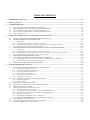
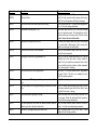
TABLE OF CONTENTS
1.
TEMPORARY START-UP:......................................................................................................................................................................1-1
2.
FINAL START-UP: .....................................................................................................................................................................................2-1
3.
CONTROLLER TYPE:..............................................................................................................................................................................3-1
3.1.
3.2.
3.3.
3.4.
3.5.
4.
OPERATION PRINCIPLE FOR CAR ZONING AND LEVELLING: .......................................................................................4-1
4.1.
4.2.
4.3.
4.4.
4.5.
4.6.
5.
TWO CAR GROOP CONTROLLER (WITHOUT DISPATCHER):............................................................................................................3-1
THREE AND MORE CAR GROUP CONTROLLER (WITH DISPATCHER):............................................................................................3-2
CLOCK SETTING ON DISP ATCHER WITH OPERATOR SCREEN:........................................................................................................3-4
CALL DISPATCH CONFIGURATION, USING THE OPERATOR SCREEN:............................................................................................3-4
PEAK HOURS SETTINGS :.....................................................................................................................................................................3-6
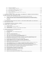
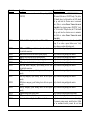
USING A TAPE SELECTOR ZONING BY MAGNET PULSES: ..........................................................................................4-1
USING A PERFORATED TAPE SELECTOR: ..........................................................................................................................4-8
4.2.1. Installation:..............................................................................................................................................................................4-8
4.2.2. Programming the number of holes for slowdown:............................................................................................................4-8
4.2.3. Verification of the right direction for high speed counter with perforated tape:..................................................... 4-10
4.2.4. Recording floor positions using perforated tape:.......................................................................................................... 4-10
PRINCIPLE WITH STANDARD TAPE SELECTOR AND GOVERNOR ENCODER:..................................................4-11
4.3.1. Positioning:........................................................................................................................................................................... 4-12
4.3.2. Programming the number of pulses for the deceleration:............................................................................................ 4-13
4.3.3. Verifying the direction of the counts from the fast counter using the governor encoder:....................................... 4-14
4.3.4. Recording floor positions using the governor encoder:................................................................................................ 4-14
HIGH SPEED COUNTER VERIFICATION:............................................................................................................................4-16
"BAR CODE" MAGNETS INSTALLATION ON EACH FLOOR: ......................................................................................4-16
4.5.1. Using magnets of 3,7,10,13 and 17" without the JRTGabarit (IP1200-TP1):......................................................... 4-17
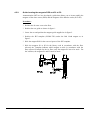
4.5.2. Guide locating the magnets DZO and P1 to P5:............................................................................................................ 4-18
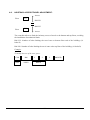
HOISTWAY ACCESS TRAVEL ADJUSTMENT: .................................................................................................................4-20
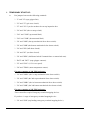
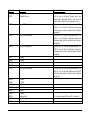
MOTOR/GENERATOR START UP:....................................................................................................................................................5-1
5.1.
5.2.
5.3.
5.4.
5.5.
5.6.
5.7.
5.8.
5.9.
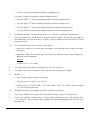
PREPARATIONS BEFORE APPLYING POWER TO THE CONTROLLER:..............................................................................................5-1
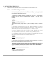
5.1.1. Motor field winding connection:..........................................................................................................................................5-1
5.1.2. Generator field winding connection....................................................................................................................................5-2
5.1.3. Generator armature connection:.........................................................................................................................................5-3
5.1.4. Motor armature connection:.................................................................................................................................................5-3
5.1.5. AC generator motor connections:........................................................................................................................................5-3
5.1.6. Tachometer connections........................................................................................................................................................5-3
ELEVATOR DC MOTOR OVERLOAD ADJUSTMENT (GOL): ...........................................................................................................5-5
5.2.1. If bimetal overload:................................................................................................................................................................5-5
5.2.2. If oil overload:.........................................................................................................................................................................5-6
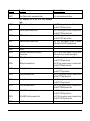
M OTOR FIELD VOLTAGE ADJUST MENT :...........................................................................................................................................5-9
M OTOR FIELD LOST PROTECTION ADJUSTMENT (RMC RELAY):...............................................................................................5-10
OPERATION SPEEDS ADJUSTMENT :................................................................................................................................................5-10
GENERATOR/ MOTOR SYSTEM ROTATION TEST :...........................................................................................................................5-11
5.6.1. Tachometer direction verification:................................................................................................................................... 5-12
5.6.2. "Armature feedback" and "contract speed" initial adjustment:.................................................................................. 5-12
5.6.3. SCURVE/ACCEL/DECEL potentiometers initial adjustment:.................................................................................... 5-12
5.6.4. Generator rotation test:...................................................................................................................................................... 5-12
5.6.5. CONTRACT SPEED potentiometer adjustment:............................................................................................................ 5-13
5.6.6. "ARMATURE FEEDBACK" current potentiometer adjustment:................................................................................ 5-14
"CLOSE LOOP" OPERATION MODE : ............................................................................................................................................5-14
A CCELERATIONS/ DECELERATIONS/ SCURVE ADJUSTMENT :.......................................................................................................5-15
GENERATOR/MOTOR FINAL ADJUSTMENT S..................................................................................................................................5-18