1
USER’S MANUAL JHD-2000 CAN A HYDRAULIC ELEVATOR CONTROLLER CANBUS PROCESSOR JHD-2000 SERIES CODE B44-07 AND B44-10 JHD-2000 CAN VERSION 1.8 TABLE OF CONTENT 1. LCD USE (JRT-LCD:.............................................................................................................................................................. 1-1 1.1. KEYBOARD: ........................................................................................................................................................................ 1-1 1.2. MENUS: .............................................................................................................................................................................. 1-2 1.2.1. Monitoring menu: ................................................................................................................................................. 1-3 1.2.2. Register Access menu: .......................................................................................................................................... 1-4 1.2.3. Active faults list menu:.......................................................................................................................................... 1-6 1.2.4. Construction mode menu: ..................................................................................................................................... 1-6 1.2.5. Recording floor position menu: ............................................................................................................................ 1-7 1.2.6. Elevator options menu: ......................................................................................................................................... 1-7 1.2.7. Password menu: ................................................................................................................................................... 1-8 2. TEMPORARY START-UP: ................................................................................................................................................... 2-1 2.1. INSTALLING THE JRT-CAN BOARD TO MANAGE THE CAR'S SIGNALS: ................................................................................. 2-1 2.1.1. JRT-CANC-1-G24 board installed in the controller: ........................................................................................... 2-1 2.1.2. JRT-CANC-1-G24 or JRT-CAN1-G24DUH board installed in the COP :........................................................... 2-2 2.2. INSTALL JUMPERS BETWEEN THE FOLLOWING TERMINALS: ................................................................................................ 2-2 2.3. SET THE PUMP MOTOR OVERLOAD RELAY: ......................................................................................................................... 2-3 2.4. CONNECTING THE PUMPING UNIT: ..................................................................................................................................... 2-4 2.5. CONNECTING THE MAIN POWER SUPPLY : ........................................................................................................................... 2-4 2.6. DIFFERENT VOLTAGES VERIFICATION:................................................................................................................................ 2-5 2.7. SYNCHRONIZING THE REVERSE PHASE RELAY (RPR): ....................................................................................................... 2-5 2.8. MOTOR THERMAL PROTECTION : ......................................................................................................................................... 2-5 2.9. CONSTRUCTION MODE: ............................................................................................................................................... 2-6 2.10. CONNECTING UP AND DOWN BUTTONS (PCH, PCB) : ............................................................................................................ 2-6 2.11. CHECKPOINTS BEFORE MOVING: ......................................................................................................................................... 2-7 2.12. MOVING THE CAR IN INSPECTION: ....................................................................................................................................... 2-7 2.12.1. Moving the car with top of car inspection : .......................................................................................................... 2-7 2.12.2. Moving the car with control inspection: ............................................................................................................... 2-7 2.12.3. Travel speed inspection : ...................................................................................................................................... 2-8 3. CONSTRUCTION START-UP: ............................................................................................................................................. 3-1 3.1. CHECKPOINTS: .................................................................................................................................................................... 3-1 3.2. CONSTRUCTION MODE: ....................................................................................................................................................... 3-1 3.3. PROCEED TO THE INSTALLATION AND MECHANICAL ADJUSTMENT OF THE FINAL LIMITS AND HOISTWAY ACCESS TRAVELLING LIMITS: .......................................................................................................................................................... 3-1 3.3.1. Final limit switches installation: .......................................................................................................................... 3-1 3.3.2. Terminal speed reducing device for elevator speed higher than 50 fpm: ............................................................. 3-2 3.3.3. Hoistway access and travel adjustment switches: ................................................................................................ 3-3 3.3.3.1. Travel limit by magnets selector tape (IP8300 BIN3 W9): ...................................................................................... 3-3 3.3.3.2. Travel limit by perforated selector tape (IP1200 2DZ BIN4): .................................................................................. 3-4 3.3.3.3. Travel limit by mechanical switch: .......................................................................................................................... 3-4 3.4. MECHANICAL SLOWDOWN LIMIT SWITCHES ACTIVATION : ................................................................................................ 3-5 3.5. PROCEED TO THE INSTALLATION AND ADJUSTMENT OF THE SELECTOR TAPE: .................................................................... 3-5 3.5.1. With standard selector tape, IP8300 BIN3 W9 model .......................................................................................... 3-5 3.5.1.1. 3.5.1.2. 3.5.1.3. 3.5.1.4. Standard selector tape installation: ........................................................................................................................... 3-6 Operation principle with standard selector tape model IP8300 BIN3 W9 ................................................................ 3-7 Magnets installation at each floor:............................................................................................................................ 3-8 Magnet installation with the IP8300-TP1 guide: ...................................................................................................... 3-9 3.5.2. Using a perforated tape (MODEL IP1200 1DZ BIN4): ..................................................................................... 3-11 3.5.2.1. 3.5.2.2. 3.5.2.3. 3.5.2.4. Mechanical installation of the perforated tape: ....................................................................................................... 3-11 Operation principle with perforated selector tape model IP1200 2DZ BIN4 ......................................................... 3-12 Installation of the "Door Zone" and bar code magnets at each floor: ..................................................................... 3-12 Magnets installation with guide (IP1200-TP1):...................................................................................................... 3-13 3.6. INSTALLATION OF THE JRT-CAN BOARD IN THE COP: .................................................................................................... 3-14 3.7. TRAVELLING CABLE CONNECTION IN THE COP :................................................................................................................ 3-15 4. FINAL START-UP: ............................................................................................................................................................... 4-17 4.1. USING STANDARD SELECTOR TAPE (IP8300 BIN3 W9 MODEL) : ...................................................................................... 4-17 4.1.1. Normal terminal stopping devices verification :................................................................................................. 4-19 4.1.2. Terminal speed reducing device for elevator speed higher than 50 fpm: ........................................................... 4-20 4.1.3. Hoistway access travel limits adjustment: .......................................................................................................... 4-21 4.2. USING A PERFORATED TAPE (MODEL IP1200 2DZ BIN4): ...................................................................................... 4-23 4.2.1. Barcode deactivation: ......................................................................................................................................... 4-24 4.2.2. High-speed counter connection verification: ...................................................................................................... 4-25 4.2.3. Floor position recording: ................................................................................................................................... 4-26 4.2.4. Quantity of holes for slowdown programming: .................................................................................................. 4-27 4.2.5. High-speed counter operation verification (count loss) : ................................................................................... 4-30 4.2.6. End of travel limit switches verification: ............................................................................................................ 4-30 4.2.7. Travel limits for pit access adjustment: .............................................................................................................. 4-32 4.3. COMMUNICATION BETWEEN THE CONTROLLER AND THE JRT-CAN BOARD VERIFICATION : ........................................... 4-34 4.3.1. Lights, jumpers and switches description: .......................................................................................................... 4-34 4.3.1.1. 4.3.1.2. 4.3.1.3. 4.3.1.4. 4.3.1.5. 4.3.1.6. 4.3.1.7. 4.3.1.8. Jumpers J1 to J6, J9, J10 : ...................................................................................................................................... 4-34 Jumpers J13, J14, J15 : ........................................................................................................................................... 4-35 Jumper JP1 : ........................................................................................................................................................... 4-36 SW3 switch: ........................................................................................................................................................... 4-37 JP2 and JP3 jumpers:.............................................................................................................................................. 4-39 J8 jumper: ............................................................................................................................................................... 4-39 JP6 Jumper: ............................................................................................................................................................ 4-40 JRT-CAN board communication error: .................................................................................................................. 4-40 4.4. ADJUSTMENTS IN AUTOMATIC MODE :................................................................................................................. 4-41 4.5. CONTROLLER'S INTERNAL FUNCTION AND SETTINGS ..................................................................................... 4-42 4.5.1. Modifying the DM using the controller's LCD: .................................................................................................. 4-42 4.5.2. Modifying options using the controller's LCD: .................................................................................................. 4-42 4.5.3. Motor protections: .............................................................................................................................................. 4-43 4.5.4. Motor control pumps, valves: ............................................................................................................................. 4-43 4.5.5. Encoder / perforated tape:.................................................................................................................................. 4-43 4.5.6. Door timers & options: ....................................................................................................................................... 4-44 4.5.7. Parking level & timers: ...................................................................................................................................... 4-44 4.5.8. Car calls options: ............................................................................................................................................... 4-45 4.5.9. Gong/Buzzer PI & voice: .................................................................................................................................... 4-45 4.5.10. Emergency recall (Fire): .................................................................................................................................... 4-46 4.5.11. Emergency power: .............................................................................................................................................. 4-47 4.5.12. Hydraulic plunger reset sequence: ..................................................................................................................... 4-47 4.5.13. Other Parameters: .............................................................................................................................................. 4-48 5. SYMBOLS LISTING: ............................................................................................................................................................. 5-1 6. MAINTENANCE: .................................................................................................................................................................... 6-1 6.1. ALARMS AND FAULTS:........................................................................................................................................................ 6-1 6.1.1. Alarms and status list: .......................................................................................................................................... 6-1 6.1.2. Automatic erasing of the alarms: .......................................................................................................................... 6-1 6.2. VOLTAGE PEAKS PROTECTION : ............................................................................................................................... 6-1 6.3. JRT-CAN-24IO BOARDS TROUBLESHOOTING:....................................................................................................................... 6-2 6.3.1. Input diagnostic: ................................................................................................................................................... 6-2 6.3.2. Output diagnostic : ............................................................................................................................................... 6-3 6.3.3. Car operating panel (COP) JRT-CAN board communication error: ................................................................... 6-4 6.4. SOFT-START DIAGNOSTIC: .................................................................................................................................................. 6-5 6.4.1. Sprecher&Schuh soft-start .................................................................................................................................... 6-5 6.4.2. Benshaw soft-start ................................................................................................................................................ 6-6 6.5. ALARMS DESCRIPTION: ..................................................................................................................................................... 6-14 APPENDIX A: SEQUENCE DESCRIPTION.............................................................................................................................. A-1 APPENDIX C: LCD MONITOR INSTRUCTIONS.................................................................................................................... C-1 NOTES AND PRECAUTIONS The controller must be installed by competent people who possess the suitable training and certifications for the installation of elevator controllers; The controller’s power supply must come from a fuse switch supplied by others. The fuses value must respect the electrical code; It is necessary to install a separate conductive element to ground the controller in the mechanical room. To know the size of the conductive element, check the electrical code. An indirect grounding (e.g. water pipes) may cause intermittent troubles and electrical noises may occur; The controller contains electrostatic sensitive devices. Before handling a component, it’s necessary to touch a grounded metal object (GND) to avoid an electrostatic discharge on it. To avoid problems caused by transportation and handling, check and tighten all the points of connections on the side "power"; from the controller’s main power supply to the motor; Please note the controller comes with a one (1) year warranty, effective on the day of billing. An improper use of the controller, an incorrect connection or the disregard of the user’s manual may void the warranty. Also note that only the components are under warranty; In case of an incorrect connection, the controller is protected by TVS which can short-circuit. Their functioning should be verified and they should be replaced if needed. Operating conditions: The 3 phases entry voltage may vary by more or less 10 %; A 60HZ frequency is standard, a 50HZ frequency is available on special order; The operating temperature is 0 to 45°C (32 to 113°F); The relative humidity is 95 %; Do not install a NEMA 1 standard enclosure in a dusty environment or where there is risk of water infiltration. Other types of enclosures are available upon request (NEMA 4, 12 etc.); Please contact Automatisation JRT Inc. if the motor is installed 50’ or more away from the controller; General information: JHD-2000 series controllers were developed for quick and easy installation and operation. The controllers have internal diagnostic functions which allow easy maintenance. There are also several functions that are user programmable. It is very important to read thoroughly the manual for a quick and secure installation. General features: Number of floors: 6 Maximum amount of cars: 6 ASME A17.1-2007/CSA B44-07 Safety code compliant CAN/CSA-B44.1/ASME 17.5 compliant Serial-link in COP (default) Field reprogrammable 1. LCD USE (JRT-LCD: This section is a summary of the supervision utility. Refer to appendix C for a complete description. The LCD allows visualizing the state of the elevator controller (floor, speed in FPM, perforated tape position, alarms, etc.), modifying the CPU’s configuration registers and also remotely recording car calls and hall call. The utility offers the possibility to have the information displayed in French or English. The utility is provided with different light-emitting diodes "LED". The "POWER" LED indicates that the utility is power supplied. The "LED2" blinks to indicate that the program is functioning normally. If the "LED2" stays on or off at all times, the program is not operational and power must be reset. When the elevator is in trouble or needs to have a manual reset, the "LCD" utility screen will blink to warn the user. 1.1. KEYBOARD: The "UP/DOWN" keys allow access to the main menus or submenus. They also allow parameter value changes. The "LEFT/RIGHT" keys allow the cursor to be placed on the parameter to be modified. The "ENTER" key allows access to a submenu. It also allows the user to save a new value. The "ESC" key allows to return to the main menu or to cancel a parameter modification. 1-1 1.2. MENUS: The "LCD" utility contains different menus available to the user. To access a menu: Press "ESC" to access the main menus list. Press the "UP/DOWN" keys to select a menu. Press "ENTER" to access the menu. The "LCD" utility has a protection that prevents accidental modification of a value or parameter by locking the menus. In order to access these menus, the user must enter the password. See section "1.2.7 Password Menu". 1-2 1.2.1. Monitoring menu: The "Monitoring" menu shows, in real-time, the elevator’s status data. This information may be used during the temporary and final start-up. At a start-up or after 2 hours of keyboard inactivity, the following screen will appear: IN AUTOMATIC PI=5 P=10 S=100 STOP Presented information: PI = Floor where the elevator is currently at. IN AUTOMATIC = Actual elevator status (See next page for the complete list). P = Perforated tape actual position (only if the controller is equipped with perforated tape). S = The actual car speed in FPM If "Soft-Start" starting type, the last line is for the "Soft-Start" status: STOP = The elevator isn’t moving. RUN = The elevator is moving. Up to speed = The elevator has reached the maximum speed. If there is more than one status in the CPU, the "LCD" will switch its display between all the active statuses every second. When the elevator controller is in floor position recording cycle, the "LCD" displays "DM483" at the position "PI=" (perforated tape only). It is possible to see if the amount of door zone magnets (DZO) is the same as the amount of floors. 1-3 1.2.2. Register Access menu: This menu allows reading and writing in one of the CPU’s register. The "DM" registers are used to configure the elevator. Press "ESC" to return to the main menus. Press the "UP/DOWN" keys to select the main menu "REGISTERS ACCESS". Press "ENTER". Register type selection: Press the "UP/DOWN" keys to select a register. Press "ENTER" to save. or Press "ESC" to go back to the previous menu. Choice of registers: DM, CH, HR and TM REGISTER TYPE? ->DM Register number selection: Press the "LEFT/RIGHT" keys to place the cursor on the digit to change. Press the "UP/DOWN" keys to change the digit. Press "ENTER" to save and to go to the next menu. Press "ESC" to return to the previous menu. 1-4 REGISTER NUMBER ->DM0000 Register Value: The register value is shown in hexadecimal and binary formats. Press "ENTER" to modify the selected register value. Press "ESC" to go back to the previous menu. DM0000 = 0001 0000000000000001 15 ^ 8 4 0 ENTER = CHG Modifying the register value: Press the "LEFT/RIGHT" keys to place the cursor on the digit to change. Press the "UP/DOWN" keys to change the digit. Press "ENTER" to save and to go back to the previous menu and visualize the new value. Press "ESC" to return to the previous menu. ->DM0000 OLD = 0001 NEW = 1234 1-5 1.2.3. Active faults list menu: LOW OIL LEVEL DETECTED HR8000 ENTER->ERASE This menu allows visualizing the different alarms in the elevator controller. The "LCD" utility displays "NO ALARM" when the elevator controller has no more alarms. Visualizing the alarms: Press "ESC" to return to the main menus. Press the "UP/DOWN" keys to select the main menu "ALARMS & CPU I/O CHECKING". Press "ENTER". Press the "UP/DOWN" keys to select the submenu "ACTIVE FAULTS LIST". Press "ENTER". Press the "UP/DOWN" keys to scroll the alarms. To erase the alarms: Press the "ENTER" key, the LCD will display a confirmation window. 1.2.4. Construction mode menu: The Construction mode temporarily disables certain detections to facilitate the elevator car construction in Inspection mode. As soon as the elevator controller is placed in Automatic mode and a call has been placed, the Construction mode will automatically be deactivated and all signals will be in function. The elevator controller must be in Inspection mode. Press "ESC" to return to the main menus. Press the "UP/DOWN" keys to select the main menu "OPERATION MODE". Press "ENTER". Press the "UP/DOWN" keys to select the submenu "CONSTRUCTION MODE". 1-6 Press "ENTER". Press "UP" to activate the Construction mode. 1.2.5. Recording floor position menu: This menu allows launching a function that registers floors when the controller uses a perforated tape for the floor positioning. Refer to section 4.2. The elevator controller must be in Inspection mode. Press "ESC" to return to the main menus. Press the "UP/DOWN" keys to select the main menu "ELEVATOR & LCD SETTINGS". Press "ENTER". Press the "UP/DOWN" keys to select the submenu "RECORDING FLOORS POSITION". Press "ENTER". Press "UP" to activate. When the elevator controller is in a floor position recording cycle, the "LCD" utility displays the value of "DM483" under "PI=" on the screen. It is possible to know if the number of door zone magnets (DZO) is the same as the amount of floors. 1.2.6. Elevator options menu: This section contains all elevator control parameters. The parameters are separated in sections. Some sections will be hidden according to the controller type and option. Refer to appendix C for a complete description. Press "ESC" to return to the main menus. Press the "UP/DOWN" keys to select the main menu "ELEVATOR & LCD SETTINGS". Press "ENTER". Press the "UP/DOWN" keys to select the submenu "ELEVATOR OPTIONS"; Press "ENTER". Press the "UP/DOWN" keys to select the desired option menu. Press "ENTER". Press the "UP/DOWN" keys to select the desired parameter. 1-7 To modify an option: Press the "LEFT/RIGHT" keys to edit the parameter. Press the "LEFT/RIGHT" keys to select the digit to modify. Press the "UP/DOWN" keys to change the digit. Press on "ENTER" to save the new value and exit edition mode. Press on "ESC" key to exit without saving. Repeat for all parameters to be changed. 1.2.7. Password menu: This menu allows entering a password to unlock the parameters modification menus. The default password is "0000". PASSWORD : 0000 Press "ESC" to return to the main menus. Press the "UP/DOWN" keys to select the main menu "PASSWORD". Press "ENTER". Entering the password: Press the "LEFT/RIGHT" keys to place the cursor on the number to modify. Press the "UP/DOWN" keys to modify the number. Press "ENTER" to save. or Press "ESC" to return to the previous menu. 1-8 2. TEMPORARY START-UP: 2.1. INSTALLING THE JRT-CAN BOARD TO MANAGE THE CAR'S SIGNALS: Determine whether the JRT-CANC-1-G24 board that manages the car's signals is installed in the controller or in the COP. If the board is a JRT-CAN1-G24DUH, it must be installed in the COP since it has control interface boards for Dupar buttons. JRT-CANC-1-G24DUH 2.1.1. JRT-CANC-1-G24 board installed in the controller: Ensure that a jumper is installed on JP1 of the JRT-CANC-1-G24 board and that the 150Ω, 2W resistance between the CL2 and CH2 terminals in the controller has been removed. The board must be immediately installed before the temporary start-up otherwise the controller will detect communication errors. 2-1 2.1.2. JRT-CANC-1-G24 or JRT-CAN1-G24DUH board installed in the COP : This option allows wires sparing in the travelling cable, it is highly suggested. As long as the board is not installed in the COP, there must be a resistance of 150Ω between terminals CL2 and CH2 of the controller. When the board is installed in the COP, the resistance between terminals CL2 and CH2 must be removed. The jumper JP1 must be installed on the board. Note: A shielded cable must be used for CL2 and CH2. For RET2, an "AWG 18" wire must be used. 2.2. INSTALL JUMPERS BETWEEN THE FOLLOWING TERMINALS: "J0" and "J5" (bypass security line); "J5" and "J8" (if there is no car top inspection box); "J9" and "J9A" (special emergency stop, PH2). "J9A" and "J10" (car stop). 2-2 "J11" and "LNH" (normal up limit); "J11" and "LNB" (normal down limit); "J11" and "LRH" (normal up slowdown limit and up speed reducing device); "LRH" and "SRD" (up speed reducing device and speed reducing device); "J11" and "LRB" (normal down slowdown limit); "J8" and "HDC" (hall doors closed); "J8" and "CDC" (car door closed); "J8" and "HDL" (hall doors locked if manual doors or motorised cam); "LTT" and "PCH" (Top travelling inspection switch); “COM” & “OILO” and “OILO” & “CT” (Motor thermal contact and overheating oil sensor); 2.3. SET THE PUMP MOTOR OVERLOAD RELAY: If Across the Line starter is used: the overload relay must be set according to motor FLA, as specified on the motor nameplate. If Star-Delta starter is used: the overload relay must be set according to the motor FLA x 0.572. Example: FLA = 22AMP 22 x 0.572 = 12.5AMP If Solid-State starter (Benshaw) is used: The parameter P1 must be set in accordance with the motor FLA. The parameter P74 (Starter Type) must be set at: ID: If 1 motor connected in Star-Delta (6 wires) NOR: If 1 motor connected Across the Line (3 wires) NOR: If 2 motors. If Solid-State starter (Sprecher+Schuh) is used: The DIP Switch #15 must be set OFF if 6 wires or ON if 3 wires. The blue potentiometer must be set in accordance with : If 6 wires: The nameplate current and following the scale ∆I 2-3 If 3 wires: The nameplate current and following the scale I "Dip Switch setting" See the electrical schematics for JRT values. For more details, see the Soft-Starter manual. Overload protection adjustment. 2.4. CONNECTING THE PUMPING UNIT: The pumping unit must be connected to the controller in accordance with the electrical schematics: Pump motor Valves Thermal contact (CT), low oil device (LOD), oil overheat (OILO), low pressure switch (LPS), if required Etc. 2.5. CONNECTING THE MAIN POWER SUPPLY : The main power supply must be connected to L1, L2 and L3 terminals. A ground wire must be provided from the main switch to the controller (GND). The 3 fuses from main switch must be removed. Turn the main switch ON and measure the voltage; it must be tie in with the electrical schematics. Turn the main switch OFF; put the fuses back in place and turn the main switch back ON. 2-4 2.6. DIFFERENT VOLTAGES VERIFICATION: Should be measured: Controller power voltage (see schematics) 120 VAC between "J" and "N", "JC" and "N". 24 VDC between "+A" and "COM", "+AC" and "COM", "+GR" and "COM", "+HPI" and "COM", "+DC" and "COM" (internal voltage). 2.7. SYNCHRONIZING THE REVERSE PHASE RELAY (RPR): If Across the Line or Star-Delta starter: the reverse phase relay (R.P.R.) must be synchronized. Yellow and green lights will turn on as soon as the phases sequence will be right. If Solid-State starter (Benshaw): the parameter P77 (Input Phase Sensitivity) must be set to ABC or CBA depending on main power phasing. If Solid-State starter (Sprecher+Schuh): the DIP Switch #9 (Phase rotation) must be set ON = ABC or OFF = CBA depending on main power phasing. 2.8. MOTOR THERMAL PROTECTION : If the controller has a thermistor relay TUS, it must be connected to the motor's P1-P2 sensor terminals. The relay must be reset by pressing its "reset" button, the red light must turn off. If the relay does not reset, the thermistor in the motor is faulty. The motor's sensors must be thermistor type (variable resistor), not thermal or dry contacts. It is possible to bypass the motor thermistor sensor, if necessary, by placing a 400 or 500 OHMS resistor, ¼ or ½ watt, across P1 and P2 terminals. If the controller has a thermal contact, its 2 wires must be connected between the input "CT" of the JRT-CAN-24ACDC board and "COM" terminals. Refer to electrical schematics. 2-5 2.9. CONSTRUCTION MODE: The "construction" mode temporarily deactivates certain detections to facilitate the elevator car construction in inspection mode. As soon as the elevator controller is placed in "automatic" mode and a call is placed, the "construction" mode will be automatically deactivated and all signals will be in function. IMPORTANT: The elevator controller must be in inspection mode With the controller’s LCD screen: Press "ESC" to return to the main menus. Press the "UP/DOWN" keys to select the main menu "OPERATION MODE". Press "ENTER". Press the "UP/DOWN" keys to select the submenu "CONSTRUCTION MODE". Press "ENTER". Press "UP" to activate the Construction mode. Deactivated circuits: Low oil device "LOD". Low pressure switch "LPS". Seismic contact "SCS". Emergency power signals "GEN1, GEN2". Switches "LRH, LRB" monitoring. Note that the switches must still be short-circuited at startup. The fire signals are completely deactivated. Car overload signal "LW2". All the outputs that set off the alarms are deactivated. At this time, it is not necessary to connect the Low oil detection "LOD", the low pressure switch "LPS" or the oil overheat contact "OILO". They will be adjusted at the final start-up. 2.10. CONNECTING UP AND DOWN BUTTONS (PCH, PCB) : Connect the "up" button across "+A" and "PCH" terminals and the "down" button across "+A" and "PCB". Do not connect "ISR" terminal. The ISR relay must be off. 2-6 2.11. CHECKPOINTS BEFORE MOVING: At this point of the procedure, please ensure: CPU inputs which must be activated: PC, PP, LNH, LNB, J9A, J9, J10, RPA, R5R. HDL (locked hall door contact if manual door or motorized cam). The relays: ISR and ISRC must not be activated. CDC, HDC and RED must be activated. RPA must be activated (if required). RPR must be in phase (is Across the line or Star-Delta start) (Yellow and green lights must be lit). If the controller has a Soft-Starter (Benshaw or Sprecher+Schuh) and an alarm is on, refer to section 6.4 of the present manual or the troubleshooting section of the Soft-Starter manual. The alarms: Hold for 2.5 seconds the "MANUAL RESET" button on the controller inspection board to reset the controller and clear the alarms. The controller will be rearmed only if all conditions are ok. By using the LCD, clear the alarms and then consult the alarms list to check that there are none active. (Section 1 for LCD usage). 2.12. MOVING THE CAR IN INSPECTION: 2.12.1. Moving the car with top of car inspection : The car can be moved in inspection mode by placing a jumper between terminals "+A" and "PCH" to go up or between terminals "+A" and "PCB" to go down. 2.12.2. Moving the car with control inspection: The car can also be moved by the controller "UP or DOWN" buttons by putting the controller’s inspection switch in Inspection mode. A jumper must be placed between terminals "+A" and "ISR", the door bypass switch and the hoistway access key must be in "OFF" position. Moving up: By pressing the up button, the PCH input light turns ON. The UCT (with Benshaw SOFT START), UCA and SU CPU outputs turn ON. The two up valves (U and US) outputs and their corresponding lights turn ON and the car starts moving up. 2-7 Moving down: By pressing the down button, the PCB input light turns on. The SD output light, the two down valves (DV and DR) outputs and their corresponding lights turn ON and the car starts moving down. 2.12.3. Travel speed inspection : The car top or control inspection speed can be done in high or low speed, the high speed being the default value. To change the speed selection: With the LCD screen, follow these instructions: Press "ESC" to return to the main menus. Press the "UP/DOWN" keys to select the main menu "ELEVATOR & LCD SETTINGS". Press "ENTER". Press the "UP/DOWN" keys to select the submenu "ELEVATOR OPTIONS"; Press "ENTER". Press the "UP/DOWN" keys to select the submenu "MOTOR CONTROL, PUMPS, VALVES"; Press "ENTER". Choose the option to be modified. OPTION FAST VALVE IN CONTROLLER INSPECTION FAST VALVE CAR TOP INSP & ACCES DESCRIPTION When the controller’s inspection switch is activated: NO = Only the low speed valve will be used. YES = Both valves will be used. When the car top inspection switch is activated: NO = Only the low speed valve will be used. YES = Both valves will be used. UNIT DM YES/NO 0129 YES/NO 0130 IMPORTANT The CPU inputs are designed to operate on 24 volts DC. DANGER: Never apply 120 volts AC for it may cause severe damage to the inputs. Upon controller reception, the "COM" terminal is grounded. 2-8 3. CONSTRUCTION START-UP: 3.1. CHECKPOINTS: Ensure that all of the temporary start-up sections have been executed. 3.2. CONSTRUCTION MODE: Ensure that the controller is in construction mode in the LCD screen: CONSTRUCTION IND=3 P=1234 V=1234 PS0 ACC0 STP 3.3. PROCEED TO THE INSTALLATION AND MECHANICAL ADJUSTMENT OF THE FINAL LIMITS AND HOISTWAY ACCESS TRAVELLING LIMITS: 3.3.1. Final limit switches installation: The same corresponding limit switches are found at the bottom floor: LRB and LNB. The down normal slowdown limit switch "LRB" activates at the same time or slightly after (max 1 inch of travel) the slowdown initiated by the selector tape. The down normal limit switch "LNB" activates as soon as the car goes slightly below the bottom floor. Ensure the slowdown is engaged by the magnets or the amount of slowdown holes in the tape rather than by the limit switches (LRH-LRB). The switches position is determined by a ratio of 6 inches per 25 FPM, minus 1 inch. 3-1 Example: 125 FPM X 6 inches = 30 inches -1 inch = 29 inches of floor 25 FPM Slowdown distance table: 50 FPM = 11 inches = 14 holes 75 FPM = 15 inches = 20 holes 100 FPM = 23 inches = 31 holes 150 FPM = 35 inches = 46 holes 200 FPM = 47 inches = 62 holes Ensure that the normal stops at top and bottom floors are not engaged by the limit switches (LNH-LNB). Note: The limit switches adjustment in accordance with the selector tape slowdown will be done during the final start-up. 3.3.2. Terminal speed reducing device for elevator speed higher than 50 fpm: If the car speed exceeds 50FPM (0,25m/s), a Terminal-Speed Reducing Device (SRD switch) must be installed for the up direction to ensure that the plunger does not strike its solid travel limit at a speed in excess of 50FPM (0,25m/s). Install the Speed Reducing Device limit (SRD) around 2” higher than the Up Slowdown limit (LRH). 3-2 LNH Normal up Limit: Activated when the car goes slightly higher than the top floor. SRD Speed reducing device: Activated when the car goes slightly higher than LRH (around 2). LRH Up normal slowdown limit: Activated at the same time or slightly after (max. 1 of travel) the slowdown initiated by the selector tape. Car Note: The limit switches adjustment in accordance with the selector tape slowdown will be done during the final start-up. 3.3.3. Hoistway access and travel adjustment switches: Depending on the speed of the elevator, there can be one or two hoistway access switches: If the speed is greater than 150FPM (0.75m/s.), hoistway access switches must be provided at: The lowest landing for pit access, when a separate pit access door is not provided; The top landing to access the car’s top. If the speed is 150FPM (0.75m/s.) or less, hoistway access switches must be provided at the top landing when the distance from the top of the car to the landing still exceeds 900mm (35 inches). Refer to latest B44 elevator code. The A17.1/B44 code requires that the movement of the car be limited in the up and down direction. 3.3.3.1. Travel limit by magnets selector tape (IP8300 BIN3 W9): This method can be used only if the floor distance does not exceed 10 feet. If this option is used, two jumpers must be installed: one between the ACT and PCB terminals and one between ACB and PCH terminals. 3-3 This feature is not enabled by default; activation will be done during the final start-up. Top landing: The program of the elevator controller detects that the elevator reached the door zone sensor (DZO) or the down slowdown sensor (DSL) of the floor just below the top floor. When the sensor DZO or DSL is reached, the down command of the hoistway access is deactivated. Activation will be done during the final start-up. Bottom landing: The program of the elevator controller detects that the elevator reached the door zone sensor (DZO) or the up slowdown sensor (USL) of the floor just above the bottom floor. When the sensor DZO or USL is reached, the up command of the hoistway access is deactivated. Activation will be done during the final start-up. 3.3.3.2. Travel limit by perforated selector tape (IP1200 2DZ BIN4): This method doesn’t require any mechanical switch; the travel limit is configurable by the LCD. If this option is used, two jumpers must be installed, one between terminals ACT and PCB and one between ACB and PCH. The travel limit zone will be adjusted during the final start-up. 3.3.3.3. Travel limit by mechanical switch: This method requires one or two mechanical switches in the hoistway and a cam about ten feet long on the car. This option is set by default in the controller. If the option is not used, two jumpers must be installed, one between terminals ACT and PCB and one between ACB and PCH. The movement of the car initiated and maintained by the access switch at the lowest landing. (ACB switch): The movement shall be limited in the up direction so that the bottom of the platform guard is even with hoistway entrance header. 3-4 ACB Car Limited the movement of the car at the lowest landing. Car at the lowest landing. The movement of the car initiated and maintained by the upper access switch. (ACT switch): The movement shall be limited: In the down direction: to a travel no greater than the distance between the car crosshead and the car platform. In the up direction: to the distance where the platform guard extends below the car platform. Car Car at the upper landing. ACT Limited the movement od the car at the upper landing. 3.4. MECHANICAL SLOWDOWN LIMIT SWITCHES ACTIVATION : Remove the jumpers from the mechanical slowdown limits (LRH, LRB). 3.5. PROCEED TO THE INSTALLATION AND ADJUSTMENT OF THE SELECTOR TAPE: 3.5.1. With standard selector tape, IP8300 BIN3 W9 model If the controller is equipped perforated selector tape, go directly to the section 3.5.2 3-5 3.5.1.1. Standard selector tape installation: 3-6 3.5.1.2. Operation principle with standard selector tape model IP8300 BIN3 W9 The steel tape is installed in the hoistway and is composed of two rows of magnets; one to control the slowdown (USL) as well as for the elevator position autocorrecting barcode, and the second one for door zone and leveling (DSL). The sensing head is located on the car and has two rows of sensors that are sensible to "north" or "south" magnets. A USL sensor (south) detects the magnets for the up slowdown while the DSL sensor (south) detects the magnets for the down slowdown. Four other sensors (North) detect the center row of magnets: LU sensor for up leveling, LD sensor for down leveling, DZO-DZO1 sensors for door zoning and three other sensors (north) P1 to P3 detect the row of magnets for the barcode. The sensors in the car-mounted tape head can be moved inside the sensing head so as to facilitate the adjustment of the car positioning. It is better and easier to move the LU and LD sensors than to cut off the magnet on the steel tape. Slowdown can be engaged by the USL sensor when going up and the DSL sensor when going down. A ratio of 6" for each 25FPM allows determining the ideal distance for an effective slowdown and also points out the magnets location. Example: 125 FPM X 6 in = 30 in 25 FPM 3-7 3.5.1.3. Magnets installation at each floor: In order to place the magnets in the correct position on the steel tape, it is recommended to bring the car at the exact position where the command has to be energized when choosing an intermediate floor. Leveling magnets (12" north magnet): Bring the car even with the floor. Place the magnet centered on the steel tape so that the DZO sensor is energized but the LU and LD sensors are not. The use of two DZO sensors gives the redundancy for the door zone. Up slowdown (south USL magnet): For example with a 100'/min speed elevator: bring the car exactly 24" below the landing floor and place the magnet on the steel tape (Right row) so that the bottom end of the magnet energizes the USL sensor. Down slowdown (south DSL magnet): For example with a 125'/min speed elevator: bring the car exactly 30" higher than the landing floor and place the magnet on the steel tape (Left row) so that the top of the magnet energizes the DSL sensor. The table below shows how to install the magnets and has the legend for a barcode up to 7 floors. Magnets required for the binary code Binary code Floors 1 2 3 4 5 6 7 P1 P2 P3 Nbr. Length (inches) 1 1 2 1 2 2 3 3 3 3 3 3 3 3 Example: 2nd floor Slide P1 P2 3 inch magnet centered with P2 P3 P1, P2, P3 = sensors located in the selector tape. "North" magnets need to be used. The binary code is only validated when sensors are ON and the elevator is centered to the floor (DZO = ON, LU 3-8 = OFF, LD = OFF). These magnets are used to correct the elevator’s position, so it is important that the magnets be correctly positioned. WARNING To position the magnets at the other floors, proceed as mentioned above or as follow: Start by placing the 12” magnet (leveling) by proceeding as described previously at the first step and binary code magnets. Then, place the USL and DSL magnets on the basis of the measurements between the USL and DSL magnets according to the leveling 12” magnet of the first floor as described previously at the second and third steps. It is strongly recommended not to secure the magnets immediately to the steel tape. If a mistake should happen in the positioning, it would still be easy to move the magnets on the tape. Wait until you have made successful tests before gluing definitely the magnets to the tape. 3.5.1.4. Magnet installation with the IP8300-TP1 guide: Automatisation JRT inc. has developed a guide permitting to quickly locate the door zone magnets (DZO) and binary code magnets (P1 to P3). Procedure: Position the elevator even with the floor. Position the row’s guide as shown in figure 1. Lower the car and place the provided magnet guide as shown in figure 2. Position the JRT template under the magnet as shown in figure 3. Secure the DZO magnet in the reserved space of the JRT template. Secure the P1 to P3 binary code magnets according to the template for the selected floor. I.E.: For the first floor, only the P1 magnet must be secured. For the third floor, magnets P1 to P2 must be secured. 3-9 3-10 3.5.2. Using a perforated tape (MODEL IP1200 1DZ BIN4): 3.5.2.1. Mechanical installation of the perforated tape: 3-11 3.5.2.2. Operation principle with perforated selector tape model IP1200 2DZ BIN4 There are no magnets on the tape for position control and slowdown activation. The holes counted on the tape control the sequences. The tape has 16 holes per foot. The installer only needs to specify how many holes the elevator needs to get to the floor and to start the slowdowns. This amount of holes is the same for each floor. To indicate the position of the door zone and of the leveling, a magnet must be installed on each floor on the left side of the tape. It is important to first install magnets at each floor. 3.5.2.3. Installation of the "Door Zone" and bar code magnets at each floor: The tape reader on the car’s top, in addition to the 2 door zones sensors, has 4 or 5 sensors that let you confirm the exact floor at each stop. Place the car exactly even with the floor. Place the magnets on the tape so that the DZO and DZO1 are activated but not LU and LD, this means centered between LU and LD. If the controller was supplied with the magnet guide (IP1200-TP1), see the following point for the car positioning. The table here under explains how to install the magnets and contains a table for a bar code up to 31 floors. 3-12 Magnets required for binary code Binary code Level 1 2 3 4 5 6 7 8 9 10 11 12 13 14 15 16 17 18 19 20 21 22 23 24 25 26 27 28 29 30 31 P1 P2 P3 P4 P5 Amnt. Length (inches) Example: 2nd floor 1 3 1 3 Slide 2 3 1 3 2 3 2 3 3 3 P1 1 3 3 “magnet 2 3 P2 Centered with 2 3 P2 3 3 P3 2 3 3 3 3 3 P4 4 3 1 3 P5 2 3 2 3 3 3 2 3 3 3 3 3 4 3 2 3 3 3 3 3 4 3 3 3 4 3 4 3 5 3 : Detectors should be activated as well as the LEDs in the junction box. P1, P2, P3, P4, P5 = sensors located in the selector tape. North magnets need to be used. The binary code is only validated when sensors are switched on and the elevator is centered on the floor (DZO = ON, LU = OFF, LD = OFF). These magnets allow correcting the elevator’s position. The right position of these magnets is important. 3.5.2.4. Magnets installation with guide (IP1200-TP1): Automatisation JRT inc. has developed a guide that allows you to locate rapidly the doors zones magnets (DZO) and the binary codes magnets (P1 to P5). Procedure: Position the elevator even to the floor. Position the row guide as shown in figure 1. Lower the car and position the magnet guide supplied as in figure 2. 3-13 Position the JRT template under the magnet as in figure 3. Secure the magnet DZO in the reserved space of the JRT template. Secure the magnets P1 to P5 for the binary code according to the selected floor, the template indicates which magnet to secure according to the selected floor. Example: for the 1st floor, only the magnet P1 has to be secured. For the 3rd floor, the magnets P1 and P2 must be secured. 3.6. INSTALLATION OF THE JRT-CAN BOARD IN THE COP: The JRT-CANC-1-G24 or JRT-CAN1-G24DUH boards should be installed in the COP. Ensure that the buttons and selectors do not touch the board when the COP door is closed. Install the board at the same height as the car call buttons since they are shallow. See next picture for an example. 3-14 3.7. TRAVELLING CABLE CONNECTION IN THE COP : When the board is installed in the COP, remove the resistor between terminals CL2 and CH2. Ensure the jumper JP1 on the board is present. If the jumper JP1 is not present, a communication error will be detected by the controller. 3-15 Use a shielded cable for CL2 and CH2 between the controller and the board. For RET2, use a "AWG 18" wire. Connections are made at the terminals located at the top of the plate. See next picture for an example: Connect the COP devices directly to the JRT-CAN board terminals. Connect all other devices (door operator, inspection box, etc…) to the travelling cable. The communication will be established in section 4.3. 3-16 4. FINAL START-UP: 4.1. USING STANDARD SELECTOR TAPE (IP8300 BIN3 W9 MODEL) : If your controller has a perforated selector tape, refer to section 4.2. At this stage the controller must be in maintenance mode to prevent the door’s automatic opening. The selector tape installation was made in section 3.5.1. For more information, refer to this section. Determine the magnet positions of USL and DSL which initiate slowdown. A ratio of 6" for each 25FPM allows determining the ideal distance for an effective slowdown and also points out the magnets location. Example: 125 FPM X 6 inches = 30 inches 25 FPM Verify and secure the up slowdown magnet (north USL magnet): For example, with a 100'/min speed elevator: bring the car exactly 24" below the landing floor and place the magnet on the steel tape so that the bottom end of the magnet energizes the USL sensor. Verify and secure the down slowdown magnet (south DSL magnet): For example, with a 125'/min speed elevator: bring the car exactly 30" higher than the landing floor and place the magnet on the steel tape so that the top of the magnet energizes the DSL sensor. Verify the positions and secure the 12 inch magnet for door zone and leveling. Move the car in inspection at each floor and verify that when the car floor and hall floor are even, DZO sensor is energized but not LU and LD sensors. While verifying the leveling magnet at each floor, also verify the binary code magnet positions for auto correction on each floor. The table below shows how to install the magnets and has the legend for a barcode up to 7 floors. 4-17 Magnets required for the binary code Binary code Floors 1 2 3 4 5 6 7 P1 P2 P3 Nbr. Length (inches) 1 1 2 1 2 2 3 3 3 3 3 3 3 3 Example: 2e floor Slide P1 P2 3 inches magnet centered with P2 P3 P1, P2, P3 = sensors located in the selector tape. "North" magnets need to be used. The binary code is only validated when sensors are ON and the elevator is centered on the floor (DZO = ON, LU = OFF, LD = OFF). These magnets are used to correct the elevator’s position, so it is important that the magnets be correctly positioned. Place car calls to verify the slowdown curves and to adjust if required the slowdown magnets (USL, DSL), the door zone magnets (LU, LD, DZO, DZO1) or the valve tuning. Keep on adjusting until the ride quality is satisfying. To place car call manually with the LCD screen, follow these instructions: Press "ESC" to return to the main menus. Press the "UP/DOWN" keys to choose "CAR CALLS & HALL CALLS ENTRY". Press "ENTER". Two possible choices: 1- Place call manually or 2- Continuous mode in maintenance. The manual mode allows placing one car call at a time. The continuous mode allows placing two calls at two different level in an adjustable time frame between the calls without door opening. This mode moves between the two selected calls until the option is deactivated. 4-18 To place a call manually, choose "1 - PLACE CALL MANUALLY". Press "ENTER". Press the "LEFT/RIGHT" keys to choose between car a hall calls, front or rear calls and press the "UP/DOWN" keys to choose the floor. Press "ENTER". To place calls in continuous mode, choose "2- CONTINUOUS MODE IN MAINTENANCE". Press "ENTER". Press the "LEFT/RIGHT" keys to choose the lower landing to be reached and Press the "UP/DOWN" keys to choose which floor. Press "ENTER". Press "UP". Press the "LEFT/RIGHT" keys to choose the higher landing to be reached and Press the "UP/DOWN" keys to choose which floor. Press "ENTER". Press "UP". For the delay between calls, press the "LEFT/RIGHT" keys. Adjust this delay tenth of seconds by pressing the "UP/DOWN" keys (0.1 sec.). Press "ENTER". Press "UP". To activate the continuous calls sequence, press the "LEFT/RIGHT" and the "UP/DOWN" keys to display YES. Press "ENTER". To deactivate the continuous calls sequence, press the "LEFT/RIGHT" and the "UP/DOWN" keys to display NO. Press "ENTER". 4.1.1. Normal terminal stopping devices verification : The switches installation has been done in section 3.3.1. Refer to this section for more information. 4-19 The same switches can be found at the bottom landing: LRB and LNB. The normal down slowdown limit LRB must be activated at the same time or after (max 1 inch) the DSL detector is activated by the magnet. The down normal limit LNB is activated when the car is slightly lower than the lowest landing. Always ensure that the slowdown is initiated by the magnets rather than by the limit switches LRH or LRB. If at the terminal landings the elevator is slower to get to a floor, the slowdown is activated by the normal terminal stopping devices (LRH or LRB). These limits will have to be readjusted. Always ensure that the normal stops to the terminal landings are not initiated by the normal limits LNH or LNB. When the car is stopped at the highest landing, verify if the processor’s LNH input is activated. If not, rise the LNH limit until the processor’s LNH input activates. Follow the same steps for the lowest landing but verify the LNB limit. 4.1.2. Terminal speed reducing device for elevator speed higher than 50 fpm: The switch installation has been done in section 3.3.2. Refer to this section for more information. If the car speed exceeds 50’/min (0,25m/s), we shall install a Terminal-Speed Reducing Device (SRD switch), for the up direction, to ensure that the plunger does not strike its solid limit of travel at a speed in excess of 50’/min (0,25m/s). 4-20 Install Speed reducing device limit (SRD) around 2” higher than the Up Slowdown limit (LRH) Up Normal Limit: Activates when the car exceeds the top floor. LNH SRD Speed reducing device: Activates when the car exceeds LRH (around 2”). LRH Normal Up Slowdown limit: Activated at the same time or after (1” max (DM132)) the slowdown is activated by the perforated tape. Car 4.1.3. Hoistway access travel limits adjustment: The switch installation has been done in section 3.3.3. Refer to this section for more information. 1st way (if the distance between floors exceeds 10 feet), mechanical switches: The car's movement initiated and maintained by the access switch at the lowest landing. (ACB switch): Place the elevator in car access mode. Place the elevator at the bottom landing. Move the car by using the lowest floor access key. The movement shall be limited in the up direction to the point where the bottom of the platform guard is even with hoistway entrance header. ACB Car Limits the car's movement. Car at the lowest landing. 4-21 The movement of the car initiated and maintained by the upper access switch. (ACT switch): Place the elevator in car access mode. Place the elevator at the top landing. Move the car by using the highest floor access key. The movement shall be limited in the down direction to a travel no greater than the height of the car crosshead above the car platform. Car Car at the upper landing. ACT Limits the car's movement. 2nd way (if the distance between floors does not exceed 10 feet): Set DM0063 = 0000 to activate the movement zone with the selector tape instead of with ACB and ACT mechanical switches. DM0063 = 0000. Activates the hoistway access limit by the sensor DZO or DSL of the tape reader. DM0063 = 0001. Deactivates the hoistway access limit by the sensor DZO or DSL of the tape reader. Mechanical switches must be installed to limit the movement of the hoistway access at the top and the bottom. Refer to 1st way. Top landing: The elevator controller program detects that the elevator reached the door zone sensor (DZO) or the down slowdown sensor (DSL) of the floor below the top floor. When the sensor DZO or DSL is reached, the hoistway access down command is deactivated. Set DM0062 = 0000 or 0001 to activate the movement zone with the DSL or DZO sensor of the selector tape. DM0062 = 0001. Deactivates the down command of the hoistway access when the DSL sensor of the floor below the top floor is reached. 4-22 DM0062 = 0000. Deactivates the down command of the hoistway access when the DZO sensor of the floor below the top floor is reached. Place the elevator in car access mode. Place the elevator at the bottom landing. Move the car by using the lowest floor access key. The movement shall be limited in the up direction. Bottom landing: The elevator controller program detects that the elevator reached the door zone sensor (DZO) or the up slowdown sensor (USL) of the floor above the bottom floor. When the sensor DZO or USL is reached, the hoistway access up command is deactivated. Set DM0059 = 0000 or 0001 to activate the movement zone with the USL or DZO sensor of the selector tape. DM 0059 = 0001. Deactivates the up command of the hoistway access when the USL sensor of the floor above the bottom floor is reached. DM 0059 = 0000. Deactivates the up command of the hoistway access when the DZO sensor of the floor above the bottom floor is reached. Place the elevator in car access mode. Place the elevator at the top landing. Move the car by using the highest floor access key. The movement shall be limited in the down direction. Go directly to section 4.3. 4.2. USING A PERFORATED TAPE (MODEL IP1200 2DZ BIN4): If the controller is not equipped with a perforated selector tape, refer to section 4.3. At this stage, the controller must be in maintenance mode to prevent the doors automatic opening. The selector tape installation has been done in section 3.5.2. Refer to this section for more information. At this stage of the procedure, verify and secure the magnets: The position of the 12 inches levelling and door zones magnets ; move the elevator in inspection at each floor and ensure that once the car and landing floors are even, the DZO and DZO1 sensors are activated but the LU and LD sensors are not. 4-23 The position of the binary code magnets allowing autocorrection at each floor. Place the car exactly even with the landing ; move the elevator in inspection at each floor and ensure that once the car and landing floors are even, the DZO and DZO1 sensors are activated but the LU and LD sensors are not. The following table indicates the proper way to install the magnets and shows a legend for a barcode up to 15 floors. Required magnets for binary code Binary code Floor 1 2 3 4 5 6 7 8 9 10 11 12 13 14 15 P1 P2 P3 P4 Amnt. Length (inches) 1 1 2 1 2 2 3 1 2 2 3 2 3 3 4 3 3 3 3 3 3 3 3 3 3 3 3 3 3 3 Example: 2nd floor Slideshoe P1 P2 3 inches magnet centered with P2 P3 P4 P5 P1, P2, P3, P4 = Sensors located in the selector tape. The magnets are of "North" type. The binary code is validated only when the sensors are activated and the elevator is centered on the landing (DZO = ON, LU = OFF, LD = OFF). These magnets allow correcting the elevator position, so it is important to correctly position them. 4.2.1. Barcode deactivation: It is possible to temporarily deactivate the barcode in case of a barcode’s sensor failure. Press "ESC" to return to the main menus. Appuyer sur les touches "UP/DOWN" jusqu’au menu principal "CONFIGURATION ASCENSEUR & LCD". 4-24 Press "ENTER". Press the "UP/DOWN" keys to reach submenu "ELEVATOR OPTIONS". Press "ENTER". Press the "UP/DOWN" keys to reach "ENCODER/BARCODE/PERFORATED TAPE". Press "ENTER". Press the "UP/DOWN" keys to reach submenu "DEACTIVATE BARCODE P1, P2, P3". Press the "LEFT/RIGHT" and "UP/DOWN" keys to enter NO or YES Press "ENTER" 4.2.2. High-speed counter connection verification: Before floor recording is done, the CPU high-speed counter must be checked so it counts in the right direction. To modify the value using the controller’s LCD screen, these instructions must be followed: Press "ESC" to return to the main menus. Press the "UP/DOWN" keys to select "REGISTERS ACCESS". Press "ENTER". Select "DM" as register type. Press "ENTER". Press the "LEFT/RIGHT" and "UP/DOWN" keys to enter 5800. Press "ENTER". Note: DM5800 is the low part and DM5801 is the high part. Example: 52 000, DM5801 = 0005 and DM5800 = 2000. 0 ----------> 10 000 000 0000 0000 1000 0000 DM 5801 DM 5800 DM 5801 DM 5800 Activate PCH signal to move the car up in inspection. The value must increment. If it doesn’t, HT1 and HT2 signals must be inverted. 4-25 4.2.3. Floor position recording: The controller must be in inspection mode. Using the LCD screen: Press "ESC" to return to the main menus. Press the "UP/DOWN" keys to reach the main menu "ELEVATOR & LCD SETTINGS". Press "ENTER". Press the "UP/DOWN" keys to reach submenu "RECORDING FLOOR POSITION". Press "ENTER". Press the "UP" key to activate the Recording floor position mode. A message will be displayed on the LCD screen. At any time, to interrupt the floor position recording, put the elevator in normal running mode. Move the car down to the lowest landing so that the down normal limit (LNB) is activated and the LU input is energized. At this point, the car must be slightly lower than the lowest landing. Move the car up in inspection speed until the normal up limit (LNH) is activated. With control’s inspection: Put the landing and car doors contact bypass switches in "STOP" position. To move in control’s inspection, place a jumper between the "+A" and "ISR" terminals. Put the inspection switch in "INSPECTION" position. Press the "UP" button to make the elevator move up. With top of car inspection: Do not connect the "ISR" terminal. The "ISR" light must be off. Place a jumper between "+A" and "PCH" terminals. Ensure that the down normal limit LNB turns on before LU. The LNB input on the CPU must turn on before LU turns off. The monitoring menu or the DM483 register allows following the floor position recording. Each time a floor is recorded; this register is incremented by 1. Thus, at the end of floor position recording, the register’s value should correspond to the amount of floor to be deserved by the elevator. If the elevator stops and the top floor is not displayed, this indicates that one or more floor were not recorded. Check the down and up normal limits and restart the floor position recording. 4-26 INSPECTION IND=5 P=10 STOP If all the floors were recorded, their positions are recorded in the processor. The recorded position is determined in amount of holes starting from the bottom. Move the car in inspection. The position indicator will increment or decrement depending on the car’s position if the quantity of holes for the slowdown has been programmed as explained in section 4.2.4. If the indicator does not appear to operate well, repeat this section. 4.2.4. Quantity of holes for slowdown programming: The suggested distance for an effective slowdown before reaching a landing is of 6 inches per 25fpm. Example: 200 fpm X 6 inches = 48 inches 25 fpm The tape has 16 holes/ft = 1 hole/0.75 inch So: 48inch = 64 holes 0.75 Slowdown distance table: 50 fpm = 12 inches = 16 holes 75 fpm = 18 inches = 24 holes 100 fpm = 24 inches = 32 holes 125 fpm = 30 inches = 40 holes 150 fpm = 36 inches = 48 holes 200 fpm = 48 inches = 64 holes The amount of slowdown holes before reaching a landing value is recorded in DM132. 4-27 To change a value using the controller’s LCD, follow these instructions: Press "ESC" to return to the main menus. Press the "UP/DOWN" keys until the main menu "ELEVATOR & LCD SETTINGS". Press "ENTER". Press the "UP/DOWN" keys to reach submenu "ELEVATOR OPTIONS". Press "ENTER". Press the "UP/DOWN" keys to reach submenu "ENCODER/BAR CODE/PERFOR.TAPE". Press "ENTER". Press the "UP/DOWN" keys to reach "DECEL DISTANCE SPD <= 225 FPM" (DM0132) Press the "LEFT/RIGHT" and "UP/DOWN" keys to enter the desired holes quantity (Example: 64 = 0064). Press "ENTER". Press the "UP/DOWN" keys to reach submenu "ADDITIONNAL COUNT IN DOWN" (DM0133). The holes quantity can be modified at any time when the car is not moving. Place car calls to verify the slowdown curves and to adjust if required the slowdown magnets (USL, DSL), the door zone magnets (LU, LD, DZO, DZO1) or the valve tuning. Keep on adjusting until the ride quality is satisfying. If the down speed is slower than the up speed, additional holes can be added to DM0133. Example: A 125 fpm down and 100 fpm up elevator. The quantity of slowdown holes adjustment (DM0132) will be made in up direction at 100 fpm. For the down speed, additional slowdown holes must be added since the speed is 125fpm. These additional holes must be added in the ADDITIONNAL COUNT IN DOWN (DM0133) parameter. The normal slowdown speed (DM0132) will be 32 holes and the additional holes in down direction value (DM0133) will be 8 holes for a sum of 40 slowdown holes for the down speed. To place calls manually using the controller’s LCD, follow these instructions: Press "ESC" to return to the main menus. Press the "UP/DOWN" keys to reach the main menu "CAR CALLS & HALL CALLS ENTRY". 4-28 Press "ENTER". Two possible choices: 1- Place call manually or 2- Continuous mode in maintenance. The manual mode allows placing one car call at a time. The continuous mode allows placing two calls at two different levels in an adjustable time frame between the calls without door opening. This mode moves between the two selected calls until the option is deactivated. To place a call manually, choose "1 - PLACE CALL MANUALLY". Press "ENTER". Press the "LEFT/RIGHT" keys to choose between car a hall calls, front or rear calls and press the "UP/DOWN" keys to choose the floor. Press "ENTER". To place calls in continuous mode, choose "2- CONTINUOUS MODE IN MAINTENANCE". Press "ENTER". Press the "LEFT/RIGHT" keys to choose the lower landing to be reached and Press the "UP/DOWN" keys to choose which floor. Press "ENTER". Press "UP". Press the "LEFT/RIGHT" keys to choose the higher landing to be reached and Press the "UP/DOWN" keys to choose which floor. Press "ENTER". Press "UP". For the delay between calls, press the "LEFT/RIGHT" keys. Adjust this delay tenth of seconds by pressing the "UP/DOWN" keys (0.1 sec.). Press "ENTER". Press "UP". To activate the continuous calls sequence, press the "LEFT/RIGHT" keys and the "UP/DOWN" keys to display YES. Press "ENTER". To deactivate the continuous calls sequence, press the "LEFT/RIGHT" keys and the "UP/DOWN" keys to display NO. Press "ENTER". 4-29 4.2.5. High-speed counter operation verification (count loss) : Put the controller in maintenance mode; the LCD should display in maintenance. MAINTENANCE IND=5 P=10 STOP If the LCD doesn't display in maintenance, check the alarm menu or deactivate the displayed mode. P = ___ indicates the real position measured in holes beginning from the LNB limit (DM0490). At each landing stop, the memorized position during the learning cycle is put back in the high-speed counter. Count loss: When the elevator moves in levelling, the Position parameter value (P=___) slowly decrease or increase (DM0490). At landing stop, pay attention to the value which will be put back in the high-speed counter after 2 seconds. If the value changes by more than 2 counts, it may be that the selector tape has missed a count or the floor position has not been correctly recorded. Redo a complete floor learning sequence and if the problem remains, check on the HT1 and HT2 shielding. Cleaning the tape head and the perforated tape may solve the problem if a perforated tape is used. Light shafts and strong incandescent lamps are circulating a great deal of infrared rays. These rays can affect the perforated tape high-speed counter's infrared sensors. 4.2.6. End of travel limit switches verification: The elevator must be adjusted before making the final adjustment to the normal slowdown limits. There are two ways to adjust the normal slowdown limits; the first one being with a measuring tape and the second one being with the position parameter (P = ___) which represent the car's position, measured in holes (DM0490). 4-30 LNH Up normal limit: activated when the car is slightly higher than the top floor. LRH Normal up slowdown limit: Activated when or after (max 1 inch) the slowdown initiated By the perforated tape or the governor's encoder. Car 1st way: If the amount of holes or pulses found in the slowdown parameter (DM0132) is 32: 32 x 0.75 inch = 24 inches. In this example, the switches should activate near the final landing, approximately 25 inches before arrival. 2nd way: LRH Adjustment: Place the car at the highest landing, even with the floor (DZO activated, LU and LD deactivated). Note the holes or pulses quantity in the position parameter (P = ___) or DM490 (ex: 500 holes or pulses). Subtract this value from DM132 (ex: 32 holes or pulses). Add 1 hole to the result and this value will determine the "LRH" normal slowdown limit placement. To check DM490, use the LCD: Press "ESC" to reach the main menus. Press the "UP/DOWN" to select "MONITORING". Press "ENTER". 4-31 MAINTENANCE IND=5 P=10 STOP Example: 500 holes or pulses (highest landing position in DM490) 32 holes or pulses = DM132 500-32 = 468 holes or pulses 468 + 1 hole = 469 holes or pulses, "LRH" normal slowdown limit placement. LRB Adjustment: Place the car at the lowest landing, even with the floor (DZO activated, LU and LD deactivated). Note the holes or pulses quantity in the position parameter (P = ___) or DM0490 (ex: 10 holes or pulses). Add to this value the DM132 and DM133 values (if additional holes in down direction). Subtract 1 hole to the result and this value will determine the "LRB" normal slowdown limit placement. Example: 10 holes or pulses (lowest landing position in DM490) 82 holes or pulses = DM132, 6 holes or pulses = DM133 10+32+6 = 42 holes or pulses 48 - 1 hole = 47 holes or pulses, "LRB" normal slowdown limit placement. 4.2.7. Travel limits for pit access adjustment: Access Floor TZ DM 256 DM 255 Floor BZ Access The controller allows limiting the travel in "access" to the extreme landings. This allows avoiding the installation of mechanical limits. DM255: Amount of holes or pulses determining the travel zone at building's lowest landing. (16 holes or pulses/ft). DM256: Amount of holes or pulses determining the travel zone at building's highest landing. (16 holes or pulses/ft). 4-32 Example: Using the LCD, follow these instructions: Press "ESC" to reach the main menus. Press the "UP/DOWN" keys to reach main menu "ELEVATOR & LCD SETTINGS". Press "ENTER". Press the "UP/DOWN" keys to reach submenu "ELEVATOR OPTIONS". Press "ENTER". Press the "UP/DOWN" to reach submenu "ENCODER/BARCODE/PERFOR.TAPE". Press "ENTER". Press the "UP/DOWN" keys to reach submenu " BOT ACCESS ZONE LIMIT (3/4 CNT) " (DM 0255, Amount of holes or pulses determining the travel zone at building's lowest landing). Press the "LEFT/RIGHT" and "UP/DOWN" keys to enter the desired holes quantity (Example 8 feet: 128 = 0128). Press "ENTER". Press the "UP/DOWN" to reach submenu " TOP ACCESS ZONE LIMIT (3/4 CNT)" (DM 0256, Amount of holes or pulses determining the travel zone at building's highest landing). Press the "LEFT/RIGHT" and "UP/DOWN" keys to enter the desired holes quantity (Example 10 feet: 160 = 0160). Press "ENTER". Verification of the car travel zone limitation activated by the lowest landing pit access: Place the elevator car in access mode. Place the elevator car at the lowest landing. Move the car using the access key at the lowest landing. The movement shall be limited in the up direction to the point where the bottom of the platform guard is even with hoistway entrance header. 4-33 4.3. COMMUNICATION BETWEEN THE CONTROLLER AND THE JRT-CAN BOARD VERIFICATION : The JRT-CANC-1-G24 or JRT-CAN1-G24DUH board installed in the COP allows to remotely communicate inputs and outputs via a 3 wires CAN bus communication network. The network allows the installation of 4 boards for a maximum of 96 inputs and 96 outputs. 4.3.1. Lights, jumpers and switches description: 4.3.1.1. Jumpers J1 to J6, J9, J10 : The 24 inputs are bidirectional. A jumper allows the operation of one or more inputs to be inverted. The jumpers are factory set. Jumper Inputs J1 0 and 1 J9 2 and 3 Postitive common 4-34 Negative common J2 4 and 5 J10 6 and 7 J3 8 and 11 J4 12 and 15 J5 16 and 19 J6 20 and 23 4.3.1.2. Jumpers J13, J14, J15 : Outputs chips settings. Jumper Output Opto J13 0 and 7 U13 J14 8 and 15 U14 J15 16 and 23 U15 4-35 Positive common Output +24v, opto UDN2981AT Negative common Output 0v, opto ULN2803AN U15 J15 U14 J14 U13 J13 4.3.1.3. Jumper JP1 : Jumper "JP1" near the T5 connection terminal allows, when shorted, the addition of a 120 ohms resistor on the end of communication line between CANH and CANL of the CAN bus port. ALWAYS PUT AN END OF LINE RESISTOR AT EACH END OF THE CAN BUS NETWORK (FIRST AND LAST MODULE). The JRT-CAN-6011 board in the controller must have the "JP1" shorted and the last I/O board JRT-CAN in the car or in the controller must also have the "JP1" jumper shorted. 4-36 4.3.1.4. SW3 switch: The JRT-CAN board can be configured using the eight position switch described as follow: Take note that the switch configuration appears on the electrical schematics and is factory set. Switch number 8 7 Description ON=CAN1 = 100kbps (default) OFF=CAN1 = 47kbps ON=Communication diagnosis mode (See next table) OFF=24 operational outputs (default) Amount of car/floor calls configuration from the 24 inputs. The board's processor holds for 1.5 seconds the corresponding output to the button pressed. Three switches are used to configure the amount of car calls on the board; the remaining inputs will not be linked to an output. Example: Call amount = 8, put switch 5 ON to obtain code 2. 4-5-6 Binary code Swch. 6 =4 Swch. 5 =2 Swch. 4 =1 (Code X) 3 inputs + 3 = Amount of inputs which are car calls. Example: Code = 2 (2 X 3) + 3 = 9 car calls on this board The outputs Out 0 to Out 8 are automatically associated to inputs IN0 to IN8. When one of these inputs is activated, the corresponding output will be held 1.5 seconds. In this example, the inputs IN9 to IN23 along with the outputs Out 9 to Out 23 are no longer linked (multiple uses). 1-2-3 I/O terminals binary network address 0 to 3 address (4 boards max. 24 x 4 = 96 I/O) Example: Address= 3, turn ON switch 2 and 1. 4-37 Note: When a switch state is changed, the JP6 must be shorted to confirm the change. Use a metal rod and touch both pins. Switch 7, diagnosis mode: this switch allows communication and switches states (SW3) to be diagnosed. Activated output Dout0 Dout1 Dout2 Dout3 Dout4 Dout5 Dout6 Dout7 Dout8 Dout9 Dout10 Dout11 Description CAN 1 has received a message CAN 1 transmitted a message RS232 received characters RS232 is transmitting characters Switch 8 state Switch 7 state Switch 6 state Switch 5 state Switch 4 state Switch 3 state Switch 2 state Switch 1 state If Dout0 and Dout1 LEDs are flashing, inspect the shielded cable between the board and the controller. If Dout1 is flashing quickly and Dout0 is flashing slowly, communication is not received. Ensure the shielded cable is not crossed over: CANH from the controller must be on CANH on the board, same for CANL on CANL. LEDs number 4 to 11 allows SW3 switches 1 to 8 states to be verified, for example: if switch 8 is ON, the Dout4 LED will be lit, etc… Note: The diagnosis mode will automatically turn off after 2 minutes. Remember to put back switch #7 in "OFF" position. JP6 SW3 4-38 4.3.1.5. JP2 and JP3 jumpers: J7 JP2, JP3 When shorted, jumpers "JP2 and JP3" allow serial communication port J7 to be activated and inputs IN21 and IN22 to be automatically deactivated. If the serial port is used, these 2 inputs must not be connected. For this type of controller, only the controller's JRT-CAN6011 board must have jumpers JP2 and JP3 shorted. JP2 and JP3 not-shorted: JP2 and JP3 shorted: 4.3.1.6. J8 jumper: Jumpers' position for communication with the LCD: Serial communication port J7 (DB-9) signals 2 and 3 configuration. For this type of controller, only the controller's JRT-CAN-6011 board must have JP8 jumpers shorted to allow the LCD to communicate, as by the following schematic: 4-39 Jumpers' position for communication with a computer: To transfer a program in the JRT-CAN-6011 board, J8 jumpers must be placed as by the following schematic: 4.3.1.7. JP6 Jumper: This jumper allows the CPU to be reset and the SW3 switch state's change to be confirmed. To reset the CPU, touch both pins with a metal object. 4.3.1.8. JRT-CAN board communication error: A communication loss is detected if the 24 output LEDs 0 to 23 flash one by one each 30 seconds or if the communication loss message is present in the alarm register. The faulty board number will be indicated in the aforementioned register. Fixes: Verify the JRT-CAN board's 24VDC supply between terminals T14-3 and T14-2. Verify the pair of shielded cables connexion between the controller and the COP. CH2 from the controller must be connected to CH2 on the JRT-CANC-1-G24 board, CL2 from the controller must be connected to CL2 on the JRT-CANC-1-G24 board and RET2 from the controller must be connected to RET2 on the JRT-CANC-1-G24 board using a #18 gage wires. 4-40 CAR WIRING CANBUS MAIN C.O.P. AUXILIARY C.O.P. (OPTIONAL) NO YES CONTROLLER YES YES Ensure the JP1 jumper near the T5 connector is found on the COP's JRT-CAN board and on the controller's JRT-CAN-6011 board. Refer to section 4.3.1.2 Verify the physical address of each car call board. Their numbers should be 0, 1, 2 and 3. Each board has its own unique address. Refer to the electrical schematics for SW3 switches 1-2-3 positions. Refer to section 4.3.1.4. 4.4. ADJUSTMENTS IN AUTOMATIC MODE : In maintenance mode, verify the slowdown curves and adjust them if needed. The maintenance mode allows placing car calls without the doors opening. Proceed with the door operator's adjustments. Refer to section 4.5.6 for the doors timer. Place the elevator in automatic by deactivating the maintenance mode. The LCD must display "In automatic". IN AUTOMATIC IND=5 P=10 STOP To erase all alarms (3 ways): Press the "MANUAL RESET" button for 2.5 seconds located on the controller's inspection board. This allows all the alarms to be erased and the controller to be reset if all functioning conditions are met. Flick 4 times the maintenance switch. 4-41 Using the LCD, erase all alarms then consult the alarm registry to ensure none are active. (Refer to the LCD chapter for instructions). IMPORTANT The CPU inputs are using 24 volts. DANGER: Do not apply 120 volts AC, the inputs could be damaged. On controller receipt, the "COM" terminal is grounded. 4.5. CONTROLLER'S INTERNAL FUNCTION AND SETTINGS Several functions and timers can be configured and adjusted in each elevator controller. 4.5.1. Modifying the DM using the controller's LCD: Using the LCD, follow these instructions: Press "ESC" to reach the main menus. Select the main menu "REGISTERS ACCES". Press "ENTER". Select "DM" as register type. Press "ENTER". Press the "LEFT/RIGHT" and "UP/DOWN" keys to enter the DM number. Press "ENTER". Press "ENTER" to modify their value. Press the "LEFT/RIGHT" and "UP/DOWN" keys to enter the new value and press "ENTER" to save changes. 4.5.2. Modifying options using the controller's LCD: Using the LCD, follow these instructions: Press "ESC" to reach the main menus. Select the main menu "ELEVATOR & LCD SETTINGS". Press "ENTER". Press the "UP/DOWN" keys to reach submenu "ELEVATOR OPTIONS ". Press "ENTER". 4-42 4.5.3. Motor protections: OPTION DESCRIPTION TOO LONG TRAVEL PROTECTION DELAY Maximum time allowed getting to another floor. This delay needs to be long enough to move from bottom to top floor with a safety margin. REVERSE LOW OIL SENSOR CONTACT DEACTIVATE LOW PRESSURE SW. LPS 4.5.4. UNIT 0.1s 0008 Reverse the polarity of the low oil sensor. YES/NO 0280 Invert the low pressure switch input (LPS). YES/NO 0116 Motor control pumps, valves: OPTION DESCRIPTION FAST VALVE IN CONTROLLER INSPECTION The elevator will move using the fast valve when the controller's inspection switch is activated. If NO, only the slow speed valve will be used. FAST VALVE CAR TOP INSP & ACCES DELAY FOR PUMP SMOOTH STOP NIGHT MODE ACTIVATION DELAY NIGHT MODE LEVELING DELAY 4.5.5. DM UNIT The elevator will move using the fast valve on top of car inspection or access operation. If NO, only the slow speed valve will be used. Delay that maintains motor rotation after the up valves turn off. This delay avoids a kick in the oil pipes. Delay before the controller switch in night mode operation. Once the night mode turns on, a counter delays the car movement for 1 or 2 minutes when the levelling up sensor turns on to re-level the car. Note: as soon the car leaves the door zone or if any trouble occurs, the night mode will be cancelled. Night mode delay before the car re-level through the LU sensor. DM YES/NO 0129 YES/NO 0130 0.1s 0009 Minute 0052 Minute 0053 UNIT DM ¾ inch 0132 ¾ inch 0133 ¾ inch 0255 ¾ inch 0256 n/a 0026 Encoder / perforated tape: OPTION DESCRIPTION DECEL DISTANCE SPD <= 225FPM DECEL DISTANCE SPD >= 250FPM BOT ACCES LIMIT (3/4 CNT) TOP ACCES LIMIT (3/4 CNT) ZONE ZONE FORCE NEW LEVEL MANUALLY 2-TOP Amount of holes counted to slow down the elevator. In general, this is the slowdown distance for 1 floor run. If the car contract speed is 200 FPM or less, this is the only slowdown distance used. On a 250 FPM job, most of the time; this is the 1 floor run slowdown distance. Amount of holes counted to slow down the elevator. This is the slowdown distance for 2 floor run and more. Amount of holes counted to determine the access came at bottom floor. Amount of holes counted to determine the access came at top floor. This option allows forcing a specific floor level to put the car out of step. This feature is useful to make a buffer test or to verify the speed 4-43 OPTION DESCRIPTION UNIT DM UNIT DM 0.1s 0000 0.1s 0001 0.1s 0002 0.1s 0066 YES/NO 0080 0.1s 0088 YES/NO 0092 0.1s 0173 YES/NO 0027 UNIT DM 0.1s 0024 YES/NO 0095 limiting device system at terminal floors. 4.5.6. Door timers & options: OPTION DESCRIPTION DOOR OPENED DEL.ON HALL CALL DOOR OPENED DEL.ON CAR CALL DOOR OPENED DEL.ON PH REOPENING Door opened time on a hall call. The timer begins to count when the door is fully opened. Door opened time on a car call. The timer begins to count when the door is fully opened. Door opened time on photocell re-opening. The timer begins to count when the door is fully opened Time before door nudging when the photocell reopens the door. The timer begins to count when the door is fully opened. The door will close at reduced speed (generally 15s). Door pre-opening when the elevator slows down and the door zone sensor activates in levelling. Delay before door begins to open when the elevator slows down and the door zone sensor activates in levelling. This delay should be long enough to see around 1.0 inch when door is 75% opened. Main landing's door opened timer activation following LW3 sensor activation, depending on DM00173 content. This delay takes effect upon main landing's door opened timer activation. The weight sensor (LW3) input is generally adjusted for 25% load. As soon as this input turns on, the doors begin to close. The door close button is not operational while the timer is activated. This feature is generally used in hospital or in building occupied by persons with reduced mobility. As soon the photocell is cut or released, the door opened timer on hall call is reset. This gives more time to place the car call when the person gets in the car with a wheel chair. DELAY BEFORE DOOR NUDGING DOOR PRE-OPENING IN LEVELING ZONE DELAY BEFORE DOOR PRE-OPENING MAIN FLOOR DOOR OPENED DELAY LW3 MAIN FLOOR DOOR OPENED DELAY LW3 RESET HALL TIMER ON PH 4.5.7. DOOR Parking level & timers: OPTION PARKING RETURN DELAY ACT. EXCLUSIVE PARKING LEVEL DESCRIPTION Delay before returning to parking level. A low value will limit the time to place car calls. For simplex elevator, 60 sec. or more is recommended. For elevator groups, 30 to 40s is recommended. Exclusive parking activation. On any type of controller, an adjuster can temporarily or permanently program a specific parking level for an elevator (Group or simplex). This parking 4-44 OPTION EXCLUSIVE PRK. DOOR OPENED EXCLUSIVE PRK. FL. LEVEL 1-TOP 4.5.8. level overrides the dispatcher parking. Open doors at parking level on exclusive parking operation. Specify floor level on exclusive parking operation. The level can be: 1, 2, 3, 4, 5… Example: for a parking at 2Z (second door zone), enter 2. If 0 is entered, the CPU will correct with 1. If a value greater than top floor is entered, the CPU will correct with top floor. UNIT DM YES/NO 0096 n/a 0097 UNIT DM YES/NO 0082 n/a 0083 YES/NO 0089 YES/NO 0090 n/a 0370 n/a 0372 UNIT DM 0.1s 0151 YES/NO 0086 0.1s 0038 YES/NO 0081 Car calls options: OPTION CAR CALLS ANTINUISANCE WITH PH NO PASSENGER RUN COUNT WITHOUT PH TOP & BOTTOM CAR CALL CANCELLED OPPOSITE DIRECT. CAR CALL LOCKING CARD READER OR CAR SECURITY KEY FOR FRONT CAR CALL CARD READER OR CAR SECURITY KEY FOR REAR CAR CALL 4.5.9. DESCRIPTION DESCRIPTION Car calls anti-nuisance protection activation in regards to photocell. If the car calls anti-nuisance is activated, the controller counts the amount of call answered without the photocell beam being interrupted. When that pre-set count is reached, all the registered car calls will be cleared. With this feature activated, every time the elevator stops at a terminal landing, car calls are cleared. With this feature activated, the controller locks the car calls opposed to the actual direction. Example: If the car moves in up direction starting at the 4th floor, 1C, 2C and 3C are not allowed. Activates floors having a card reader or car security key for front car calls. Example: Card reader present at floor 1 to 5, DM0370 value will be: 0000000000011111 in binary. The value to enter in DM0370 = 001F in hexadecimal. Activates floors having a card reader or car security key for rear car calls. Example: Card reader present at floor 1 to 3, DM0370 will be: 0000000000000111 in binary. The value to enter in DM0370 = 0007 in hexadecimal. Gong/Buzzer PI & voice: OPTION FIRE RETURN BUZ.TURN OFF DELAY CAR CALL ACCEPTANCE SIG. CCA BUZZER SIG. PULSE DURATION ACTIVATE PASSING DESCRIPTION Fire buzzer turn off delay. If the fire buzzer needs to be heard during all the main floor return, enter 9999 in that register. Activation of the car calls acceptance Buzzer pulse. (CCA) Car calls acceptance pulse duration time. Passing gong (GP) activated 4-45 OPTION DESCRIPTION UNIT DM YES/NO 0093 YES/NO 0039 YES/NO 0126 n/a 0160 YES/NO 0160 n/a 0161 n/a 0162 n/a 0163 UNIT DM Enters the designated floor recall level. n/a 0098 Enters the alternate floor recall level. n/a 0099 YES/NO 0148 YES/NO 0149 YES/NO 0152 0.1s 0153 0.1s 0154 0.1s 0155 YES/NO 0056 YES/NO 0051 GONG GP ACTIVATE VOCAL ANNUNCIATOR FL. NAME WHEN PASSING EACH FLOOR BINARY CODE INDICATOR ABCDE PI UNDEF. STOP PERIOD CODE 3-99 PI DISPLAY CODE IND/FIRE/INSPECT PI INDEPENDENT SERVICE CODE3-99 PI FIRE SERVICE CODE 3-99 PI INSPECTION SERVICE CODE3-99 4.5.10. In car vocal annunciator activated. If NO, the SPE output will not trigger and no messages outputs will activate. If = YES, each floor name will be announced during a multiple floor ride. If = NO, floor name will only be announced at arrival in levelling. If = NO, standard indicator (one light per floor). A timer turns off the light after 30 min. to avoid burning the light cover If = YES, binary indicator A, B, C, D. 0 = no flashing code on the position indicator. 1 = flashing code for inspection, independent service and phase 1. 2 or more = flashing code for out of service. Out of service: fault, independent service, inspection or maintenance. When enabled, this feature sends three different codes to the position indicator following these situations: Independent service, Fire, Inspection. When the car moves, the actual position will be sent to the position indicator. Flashing code indicating the elevator is in independent service (3 to 99). Flashing code indicating the elevator is in phase 1 (3 to 99). Flashing code indicating the elevator is in inspection service (3 to 99). Emergency recall (Fire): OPTION DESIGNATED RECALL FLOOR ALTERNATE RECALL FLOOR DESIGNATED REAR DOOR ? ALTERNATE REAR DOOR ? LEVEL LEVEL LEVEL LEVEL FIRE SIGNALS INPUTS REVERSING ALTERNATE SIGNAL INPUT ON DELAY HOISTWAY FIRE -> ALTERNATE LEVEL MACHINE ROOM FIRE DESCRIPTION Specify if the designated level has to open the rear door. (YES = rear) (NO = front). Specify if the alternate level has to open the rear door. (YES = rear) (NO = front). Inverts fire signals: FS, ALT, FH, FMR. YES = input off, turns on fire sequence. NO = input activated, turns on fire sequence. On delay filter for ALT fire signal (0 to 1.0s) If = 1234, the signal is deactivated. On delay filter for FMR fire signal (0 to 1.0s) If = 1234, the signal is deactivated. On delay filter for FMR fire signal (0 to 1.0s) If = 1234, the signal is deactivated. Floor return selection for hoistway fire FH: YES = return to alternate level. NO = return to designated level. Floor return selection for machine room fire 4-46 OPTION -> ALT LEVEL RESET PHASE 1 WITHOUT RFP SIG. PH2, DOOR CLOSE MOMENTARY PRESS. 4.5.11. UNIT DM FMR: YES = return to alternate level. NO = return to designated level. If the fire selector does not have a RESET fire position (RFP input), enter YES. The fire will be reset when door is opened without any fire signal activated at the designated level. Feature required in some USA states. In phase 2, firemen do not need to hold the door close button to close the door, only a momentary pressure. Feature required in some USA states. YES/NO 0057 YES/NO 0058 UNIT DM YES/NO 0285 YES/NO 0019 UNIT DM YES/NO 0375 0 to 7 0376 HH:MM 0397 HH:MM 0398 0.1s 0387 Minutes 0389 0.1s 0388 YES/NO 0390 Emergency power: OPTION INVERT GEN1 AND GEN2 CONTACTS NORMAL OPERATION ON GENERATOR 4.5.12. DESCRIPTION DESCRIPTION GEN1 and GEN2 signals input reversing. Normal operation operation. on emergency power Hydraulic plunger reset sequence: OPTION DESCRIPTION TELES. CYLINDERS RESET SEQUENCE Activation of the cylinders reset sequence. DAY (0 = SUN, 7 = EVERY DAYS) Reset sequence days selection. (0= Sunday, 1= Monday, 2= Tuesday, 3= Wednesday, 4= Thursday, 5= Friday, 6= Saturday, 7= Every day of the week) 1st RESET (HH:MM) First reset sequence time. 2nd RESET (HH:MM) START SEQ. DELAY WITHOUT SU/SD DIR. SEQ. CANCEL DEL. IF NOT STARTING SYNCHRO SEQUENCE OPERATION TIME SYNCHRO SEQ MAN. ACTIVATION (TEST) Second reset sequence time. (Second reset can be deactivated by entering 9999) Delay before the cylinder reset is initialized once the desired day and time are met. The car must be stopped and free of any condition preventing this sequence. Protection delay to turn off the reset sequence if the elevator did not start lowering to bottom floor. Duration of the car lowering on the buffers. (Between 5 and 120 seconds) Manual activation of the reset sequence for immediate testing. 4-47 4.5.13. Other Parameters: OPTION DESCRIPTION UNIT DM NB STARTS BEFORE FAULTS RESET Amount of starts before the alarms HR80 to HR88 are automatically reset. The LCD alarms history will not be erased. n/a 0275 Invert the car stop switch input. YES/NO 0258 Invert the load weight system outputs. YES/NO 0279 Deactivates the bar code sensors (P1, P2, P3, etc.) This is for temporary bar code failure. The elevator will correct its position at terminal landings using LRH and LRB. Once the problem is resolved, put NO to reactivate the bar code system. YES/NO 0029 INVERT CAR STOP SWITCH INPUT SA INVERT LOAD WEIGHT INPUTS DEACTIVATE CODE P1, P2, P3. BAR 4-48 5. SYMBOLS LISTING: SA: HDC: HDL: CDC: LNB: LNH: LRH: LRB: DZO/DZO1: LU: LD: DOL: DCL: RDOL: RDCL: BDS: RBDS: PH: RPH: ISR: ISRC: BC-2C.3C…: CR1-CR2…: 2D-3D, 4D…: BU-2U, 3U…: SI: USL: DSL: SU: SD: OP: ROP: CL: RCL: RED: XIN: UPDW: GEN1: Car stop switch signal Landing door relay Landing door locked Car door relay Down normal limit switch Up normal limit switch Up slowdown limit switch Down slowdown limit switch Door zone Up leveling Down leveling Opened door limit switch Closed door limit switch Rear opened door limit switch Rear closed door limit switch Safety edge Rear safety edge Door photocell Rear door photocell Inspection relay Inspection control relay Car calls Card reader Down hall calls Up hall calls Independent service Zone count + up slowdown signal Zone count + Down slowdown signal Car going up Car going down Door opening contactor Rear door opening contactor Door closing contactor Rear door closing contactor Trouble redundancy relay Hoistway access relay Movement inspection relay Emergency power signal 5-1 GEN2: UG1, UG2: AIF/CIF: FS (output): INC: BUZ: FS (input): ALT: FMR: FRA: GP: GU: GD: UCA: U: US: DV: DL: UC: C1, C2, C3: TUC: UCT: RDY: RSD: BAC: SPE: SRD: RPR: RPA: RS1: TUS: CT: LOD: SCS: RCT: Pre Emergency power signal Emergency power selector Position indicator supply Low speed nudging relay Phase 1 activated Phase 1, nudging, car call acceptance buzzer Main floor recall on fire alarm Alternative floor recall on fire alarm Fire recall to main floor (machine room / hoist signal) Fire recall to alternate floor (machine room / hoist signal) Passing gong Car gong with up arrow light Car gong with down arrow light Motor relay Up fast speed valve relay Up slow speed valve relay Down fast speed valve relay Down slow speed valve relay Main motor contactor for motor Auxiliary main contactor for motor Star-delta timer Off delay relay (If solid state starter) Fault solid state starter relay Reset solid state starter relay Bypass car stop switch Speech enables (voice annunciator) Speed reducing device (50’/min and more) Reverse phase relay 120vac supply relay. (If RescuPower or UPS) Overload relay Thermistor protection relay Thermal contact or Thermistor Low oil device Seismic Reset cylinder 5-2 6. MAINTENANCE: 6.1. ALARMS AND FAULTS: 6.1.1. Alarms and status list: The CPU memorizes several alarms and status which can be seen using the LCD screen. All status and alarms are memorized in retentive registers "HR" and will be retained on a power loss. To reset all the alarms (3 different ways): Hold for 2.5 seconds the "MANUAL RESET" button on the controller inspection board to reset the controller and clear the alarms. The controller will be rearmed only if all conditions are ok. Activate the "MAINTENANCE" switch 4 times in a row. With the LCD: Visualizing the alarms: Press "ESC" to return to the previous menu. Press the "UP/DOWN" keys to select the main menu "ALARMS & CPU I/O CHECKING". Press "ENTER". Press the "UP/DOWN" keys to select the submenu "ACTIVE FAULTS LIST". Press "ENTER". To erase the alarms: Press the "ENTER" key, the LCD will display a confirmation window. 6.1.2. Automatic erasing of the alarms: If an alarm occurred but the situation has been corrected, after a certain amount of trips, the controller will automatically erase the registered alarms. DM275 contains the amount of trips before the alarms are erased. So, if DM275 holds the value 50, the alarms will be erased after every 50 trips made by the elevator. In the LCD, the alarms list will be erased, but the history will still hold the last 20 registered alarms. 6.2. VOLTAGE PEAKS PROTECTION : Note that the controller is protected by "TVS" (transient voltage suppressor) which may cause short-circuit on a bad wiring. They must be inspected and replaced as needed. 6-1 To properly inspect them, place an ohmmeter probes on the "TVS" terminals. If the measured value is 0, the "TVS" are short-circuited. 6.3. JRT-CAN-24IO BOARDS TROUBLESHOOTING: 6.3.1. Input diagnostic: If an input is always, or never, activated, check the following points: Inspect the jumpers to see if they are missing or misplaced. Refer to section 4.3 for the jumpers' configuration and consult the electrical schematics. Verify that the input is receiving 24VDC. If so, the corresponding input LED must be lit and the input activated in the program. If the input LED is unlit, the input is defective and the LTV 844 or PC844 optocoupler must be changed. To check if the input is activated in the program using the controller's LCD, follow these instructions: Press « ESC » to reach the main menus. Press the « UP/DOWN » VERIFICATION ». keys to select menu « ALARMS & I/O Press « ENTER ». Press the « UP/DOWN » keys to select sub-menu « PROCESSOR I/O VERIFICATION ». Press « ENTER ». Press the « UP/DOWN » keys and enter the channel to be verified (ex. CH 0002). Refer to the electrical schematics to select the channel to be verified. The register value is shown in hexadecimal and binary format. 6-2 CH0002 = 0001 0000000000000001 15 ^ 8 4 0 In this example, the input 0000 of the CH 0002 channel is activated. 6.3.2. Output diagnostic : If an output is always, or never, activated, check the following points: Inspect the jumpers to see if they are missing or misplaced. Refer to section 4.3.1.2 for the jumpers' configuration and consult the electrical schematics. Verify that the output is receiving 24VDC. If so, the corresponding output LED must be lit and the output activated in the program. If the output LED is unlit, the output is defective and the ULN2803AN or UDN2981AT optocoupler must be changed. To check if the output is activated in the program using the controller's LCD, follow these instructions: Press « ESC » to reach the main menus. Press the « UP/DOWN » VERIFICATION ». keys to select menu « ALARMS & I/O Press « ENTER ». Press the « UP/DOWN » keys to select sub-menu « PROCESSOR I/O VERIFICATION ». Press « ENTER ». Press the « UP/DOWN » keys and enter the channel to be verified (ex. CH 0102). Refer to the electrical schematics to select the channel to be verified. The register value is shown in hexadecimal and binary format. 6-3 CH0102 = 0012 0000000000010010 15 ^ 8 4 0 In this example, the input 0001 and 0004 of the CH 0102 channel are activated. 6.3.3. Car operating panel (COP) JRT-CAN board communication error: A communication loss is detected if the 24 output LEDs from 0 to 23 flashes one by one every 30 seconds or the communication loss notification is present in the alarms register. The faulty board number will be indicated. Corrections : Check the JRT-CANC-1-G24 board's 24vdc supply between terminals T14-3 and T14-2. Inspect the pair of shielded wires connexion between the controller and the COP. CH2 from the controller must be connected to CH2 on the JRT-CANC-1-G24 board, CL2 from the controller must be connected to CL2 on the JRT-CANC-1G24 board and RET2 from the controller must be connected to RET2 on the JRTCANC-1-G24 board by #18 gauge wire. CAR WIRING CANBUS MAIN C.O.P. CONTROLLER AUXILIARY C.O.P. (OPTIONAL) NO YES YES YES Ensure the JP1 jumper near the T5 connector is found on the JRT-CANC-1-G24 board in the COP and on the controller's JRT-CAN-6011. Refer to section 4.3.1.2 Check the physical address of each car call board. Their numbers should be 0, 1, 2, and 3. Each board has its own unique address. Refer to the electrical schematics for the switches 1-2-3 position for SW3. Refer to section 4.3.1.4. 6-4 6.4. SOFT-START DIAGNOSTIC: 6.4.1. Sprecher&Schuh soft-start « Dip Switch setting » Refer to electrical schematics for JRT values. For additional details, refer to the manufacturer's manual. Overload protection adjustment. Fault light RUN/FAULT light: The RUN/FAULT light indicates the starter status. Unlit LED = Starter off or no run command. Lit LED = Starter in function, start, run or stop. Flashing LED = The starter is in fault, refer to the following table for diagnostic. The flash count allows to determine the starter's fault. Example: If the light flashes 2 times, the hight temperature fault is activated. 6-5 6.4.2. Benshaw soft-start For this starter type, faults and alarms appear on the two eight-segment LEDs. Message starts with "A" (Alarm), this message doesn't stop the starter, refer to the Benshaw manual for more details. Message starts with an "F" (Fault), this message stops the starter. Example: F02 means overload fault. See the following table for fault diagnostic. 6-6 6-7 6-8 6-9 6-10 6-11 6-12 6-13 6.5. ALARMS DESCRIPTION: Alarms #: HR8000 HR8001 HR8002 HR8003 HR8004 HR8005 HR8006 HR8007 HR8008 HR8009 HR8010 HR8011 HR8012 HR8013 HR8014 Description: Low oil level detected. (The elevator returns to main floor) Available Excessive travel time. Causes et verifications Check the oil level in the tank. The elevator has moved at low speed. Verify LRH / LRB mechanical switches. Verify the switches that energize the valves. Ensure the valves are proper functioning. Phase lost / reversed detection Verify the controller’s main input voltage, supply and the RPR relay contact. Weight sensor LW2 was activated. Verify the weight load device that activated the LW2 input. Overheating motor thermal contact CT Verify the motor's condition and the state of the thermal contact (input CT). Overheating oil sensor detection OILO. Verify the state of the thermal sensor that activated the input OILO. The door zone sensor DZO remained activated out of the levelling Verify the tape head. The sensor remained activated. zone. DZO door zone sensor did not operate properly in levelling zone. Verify the tape head. The sensor did not activate. Overload motor relay detection RS1. Verify the state and/or the adjustment of the relay RS1. LU Levelling Up sensor did not operate properly in levelling Verify the relay and sensor operation in the top of car zone. reader connecting box. LD Levelling Down sensor did not operate properly in levelling Verify the relay and sensor operation in the top of car zone. reader connecting box. DCL switch did not open when front door closed. Verify DCL switch operation. The switch did not open before the DM0032 delay, when front door closed, with HDC and CDC switches closed. DCL did not close when front door opened. Verify DCL switch operation. The switch did not close when the front door opened, with DOL switch opened, CDC and HDC switches closed. The DCL switch opened more than a half second while the front door was completely opened. DOL switch did not open when front door opened. Verify DOL switch operation. The switch did not open 6-14 Alarms #: Description: HR8015 DOL switch did not close when front door closed. HR8100 RDCL switch did not open when rear door closed. HR8101 RDCL switch did not close when rear door opened. HR8102 RDOL switch did not open when rear door opened. HR8103 RDOL switch did not close when rear door closed HR8104 HDC landing doors contact did not close when doors closed. HR8105 CDC car doors contact did not close when doors closed HR8106 CDC or HDC contacts did not open when doors opened. 6-15 Causes et verifications when the front door is completely opened, or the door did not completely open after 12 seconds on door opening instruction when DCL switch and OP relay are closed. Verify DOL switch operation. The switch did not close when the front door closed, with DCL switch opened and HDC closed. Verify RDCL switch operation. The switch did not open before DM0032 delay when rear door is closing, with CDC and HDC switches closed. Verify RDCL switch operation. The switch did not close when rear door opened, RDOL switches opened, CDC and HDC switches closed. The RDCL switch opened more than a half second while the rear door was completely opened. Verify RDOL switch operation. The switch did not open when rear door opened or the door did not fully open after 12 seconds on door opening instruction when RDCL switch and ROP relay are closed. Verify RDOL switch operation. The switch did not close when rear door closed, with RDCL switches opened and HDC closed. Verify HDC landing doors contact. The contact did not close when door was fully closed, after 20 seconds, DCL and RDCL opened CL and RCL relays activated. Verify DCL and RDCL switches operations. Verify CDC car doors contact. The contact did not close when door was fully closed, after 20 seconds, DCL and RDCL opened CL and RCL relays activated. Verify DCL and RDCL switches operations. Verify CDC and HDC operation. CDC and HDC contacts did not open when doors opened, DCL and RDCL switches opened. Verify if either contact is Alarms #: Description: HR8107 Front door did not close completely after 5 attempts. HR8108 Rear door did not close completely after 5 attempts. HR8109 HR8110 Available Down valve failure. HR8111 HR8112 HR8113 HR8114 HR8115 HR8200 HR8201 Causes et verifications short-circuited or DCL and RDCL switches operation. This fault can occur if those switches are not opened when HDC and CDC are fully closed. Verify doorway. Something might be blocking. Check HDC and CDC contacts operation. Also check DCL switch operation. Verify doorway. Something might be blocking. Check HDC and CDC contacts operation. Also check RDCL switch operation. The elevator exceeded the travelling delay while starting in down direction. Check the valves' circuits. Ensure the valves proper functioning. J9 security line was opened. J9 security line opened while the elevator was moving or 4 seconds after it had stopped. Verify security line switches (see drawings for more details). Solid state starter (soft-start) fault. Refer to solid state starter user manual to access the error list. C3 or UC (if Soft-start) contactor failure or phase lost/reversed On up command, verify the contactor C3 or UC (if Softdetection. start) and the phase detection relay "RPR". The low pressure switch was activated Verify the low pressure switch (LPS) and the pressure in the line between the cylinder and the valve. Following guide is activated. Verify the following guide switch on the hydraulic cylinder. Perforated tape reader malfunction. The processor receives too many or not enough pulses from the perforated tape. Verify HT1 and HT2 indicators operation on the processor (they should be flashing when the elevator is moving). Clean both infrared transmitters and the hoistway mirror. Servo valve failure (EMV from Maxton, LRV from Bucher … After 3 attempts to reset the servo valve (in 2 minutes), refer to drawings) the elevator is shut down. To restore normal operation mode, cycle the power or press the manual reset button. Refer to the servo valve user manual to access the error 6-16 Alarms #: Description: Causes et verifications list. HR8202 HR8203 HR8204 HR8205 HR8206 HR8207 HR8208 HR8209 HR8210 HR8211 HR8212 HR8213 HR8214 HR8215 HR8300 Servo valve following error (EMV from Maxton, LRV from If the problem occurs in the « up » direction, a lowering Bucher … refer to drawings) sequence will be initiate. If the problem occurs in the « down » direction, the movement in the « down » direction will be not allowed, but calls above the car position will be authorized. If the problem occurs in both directions, the elevator is shut down and a manual reset is required. Refer to the servo valve user manual to access the error list. Available Uncontrolled elevator speed. Check functioning of valves relays U, US, DV and DL Available Available Available The elevator moved in the wrong direction Ensure the motor and valves are functioning properly according to the car's direction. Ensure the contactor's are correctly activating. Ensure the perforated tape counter is properly functioning and increment appropriately (see DM5800). Car door contact CDC relay opened during movement out of door Verify CDC contacts operation and clean them. zone. Hall door contact HDC relay opened during movement out of Verify HDC contacts operation and clean them. This door zone. can occur when mechanics open the hall doors with a lunar key while the elevator is moving. Available Available Available Available Available LRH/1 and LRB/1 top and bottom slowdown limit were activated Verify electrical wiring and physical contacts. 6-17 Alarms #: Description: Causes et verifications HR8310 HR8311 HR8312 at the same time. LRB1 bottom slowdown limit did not operate properly. LRH1 top slowdown limit did not operate properly. LRB bottom slowdown limit did not operate properly. LRH top slowdown limit did not operate properly. SLB/1 and SLH/1 emergency speed limiting devices were activated at the same time. SLB1 bottom emergency speed limiting device did not operate properly. SLH1 top emergency speed limiting device did not operate properly. SLB bottom emergency speed limiting device did not operate properly. SLH top emergency speed limiting device did not operate properly. LNB down normal limit switch failure. LNH up normal limit switch failure. Motor overload detected by the drive Motor overload. HR8313 Earthquake Service HR8314 Wrong LRB adjustment. HR8315 Wrong LRH adjustment. HR8400 HR8401 Available Available HR8301 HR8302 HR8303 HR8304 HR8305 HR8306 HR8307 HR8308 HR8309 6-18 Verify electrical wiring and physical contacts. Verify electrical wiring and physical contacts. Verify electrical wiring and physical contacts. Verify electrical wiring and physical contacts. Verify electrical wiring and physical contacts. Verify electrical wiring and physical contacts. Verify electrical wiring and physical contacts. Verify electrical wiring and physical contacts. Verify electrical wiring and physical contacts. Verify electrical wiring and limit switch contact. Verify electrical wiring and limit switch contact. Verify the motor’s electrical connexion and its voltage (D2 parameter, motor current, inside the drive). Ensure no mechanical trouble prevents the car from moving. Verify the state of the inputs "Seismic switch" and "Counterweight derailment switch" and reset the sequence with the button "Reset earthquake service". The limit is too far from the slowdown point. The DM360 is even to the holes difference between the slowdown point and the slowdown limit. Readjust consequently. The limit is too far from the slowdown point. The DM364 is even to the holes difference between the slowdown point and the slowdown limit. Readjust consequently. Alarms #: HR8402 HR8403 HR8404 HR8405 HR8406 HR8500 Description: Causes et verifications Available Available Available Available Available DZO relay did not activate. HR8501 DZO relay contacts remained closed. HR8502 HR8503 HR8506 Available Available LU and LD levelling sensors were activated at the same time. HR8507 ISR relay did not activate. HR8508 ISR relay has remained closed. HR8509 HDC relay did not activate. HR8510 HDC relay has remained closed. HR8511 CDC relay did not activate. HR8512 CDC relay has remained closed. HR8513 BAC relay did not activate. HR8514 BAC relay has remained closed. HR8600 FCSB relay has remained closed. HR8601 FCSB relay did not activate. Verify DZO relay operation, because it did not activate when the CPU DZO input activated. Verify DZO relay operation, because it remained closed when the CPU DZO input deactivated 6-19 Verify LU and LD relays operation. Verify the sensor operation in the top of car reader connecting box Verify ISR relay operation, because it did not activate when the CPU ISR input activated Verify ISR relay operation, because it remained closed when the CPU ISR input deactivated Verify HDC relay operation, because it did not activate when the CPU HDC input activated Verify HDC relay operation, because it remained closed when the CPU HDC input deactivated Verify CDC relay operation, because it did not activate when the CPU CDC input activated Verify CDC relay operation, because it remained closed when the CPU CDC input deactivated Verify BAC relay operation, because it did not activate when the CPU BAC input activated Verify BAC relay operation, because it remained closed when the CPU BAC input deactivated Verify FCSB relay operation, because it remained closed when the CPU FCSB input deactivated Verify FCSB relay operation, because it did not activate when the CPU FCSB input activated Alarms #: HR8602 HR8603 Description: Reset governor switch or relay remained closed XIN or XIN1 relay did not activate. HR8604 XIN or XIN1 relay has remained closed. HR8605 RED relay did not activate. HR8606 RED relay has remained closed. HR8607 LU relay did not activate. HR8608 LU relay has remained closed. HR8609 LD relay did not activate. HR8610 LD relay has remained closed. HR8611 HDL relay did not activate. HR8612 HDL relay has remained closed. HR8613 24 Volts DC +A power failure. HR8614 UC contactor did not activate. HR8615 UC contactor has remained closed. HR8700 RCT relay did not activate. HR8701 RCT relay has remained closed. HR8702 Available Causes et verifications Verify reset switch or RG relay Verify XIN or XIN1 relay operation, because it did not activate when the CPU XIN or XIN1 input activated Verify XIN or XIN1 relay operation, because it remained closed when the CPU XIN or XIN1 input deactivated Verify RED relay operation, because it did not activate when the CPU RED input activated Verify RED relay operation, because it remained closed when the CPU RED input deactivated Verify LU relay operation, because it did not activate when the CPU LU input activated Verify LU relay operation, because it remained closed when the CPU LU input deactivated Verify LD relay operation, because it did not activate when the CPU LD input activated Verify LD relay operation, because it remained closed when the CPU LD input deactivated Verify HDL relay operation, because it did not activate when the CPU HDL input activated Verify HDL relay operation, because it remained closed when the CPU HDL input deactivated Verify protection fuse. The filament could be defective. There may have been short-circuited. Verify UC contactor operation, because it did not activate when the CPU UCA output activated Verify UC contactor operation, because it remained closed when the CPU UCA output deactivated Verify RCT relay operation, because it did not activate when the CPU RCT output activated Verify RCT relay operation, because it remained closed when the CPU RCT output deactivated 6-20 Alarms #: HR8703 HR8704 HR8705 HR8706 Description: Causes et verifications HR8800 Available Available Available Up direction fast speed valve “U or ULS valve” had activated when the “U” relay did not activate. Up direction fast speed valve “U or ULS valve” did not activate when the “U” relay activated. Up direction slow speed valve “US or UDS valve” had activated when the “US” relay did not activate. Up direction slow speed valve “US or UDS valve” did not activate when the “US” relay activated. Down direction fast speed valve “DV or DMS valve” had activated when the “DV” relay did not activate. Down direction fast speed valve “DV or DMS valve” did not activate when the “DV” relay activated. Down direction slow speed valve “DL or DLS valve” had activated when the “DL” relay did not activate. Down direction slow speed valve “DL or DLS valve” did not activate when the “DL” relay activated. Communication lost with the JRT-CAN-MAS HR8801 Communication lost with the JRT-CAN-HCI HR8802 Communication lost with the Car B duplex HR8803 Communication lost with the module 0 JRT-CAN-24IO HR8804 Communication lost with the module 1 JRT-CAN-24IO HR8805 Communication lost with the module 2 JRT-CAN-24IO HR8806 Communication lost with the module 3 JRT-CAN-24IO HR8707 HR8708 HR8709 HR8710 HR8711 HR8712 HR8713 6-21 Verify U relay operation. Verify U relay operation. Verify US relay operation. Verify US relay operation. Verify DV relay operation. Verify DV relay operation. Verify DL relay operation. Verify DL relay operation. Verify connections, supply (See CANBUS manual) Verify connections, supply (See CANBUS manual) Verify connections, supply (See CANBUS manual) Verify connections, supply (See CANBUS manual) Verify connections, supply (See CANBUS manual) Verify connections, supply (See CANBUS manual) Verify connections, supply (See CANBUS manual) and switches configuration. and switches configuration. and switches configuration. and switches configuration. and switches configuration. and switches configuration. and switches configuration. Alarms #: HR8807 Description: Hall network was opened HR8808 Communication lost with the module 4 JRT-CAN-24IO HR8809 Communication lost with the module 5 JRT-CAN-24IO HR8810 Communication lost with the module 6 JRT-CAN-24IO HR8811 Communication lost with the module 7 JRT-CAN-24IO HR8812 Light curtain fault. HR8813 HR8814 HR8815 Available Available Door jammed on opening. Causes et verifications Verify connections, supply and switches configuration. (See CANBUS manual) Verify connections, supply and switches configuration. (See CANBUS manual) Verify connections, supply and switches configuration. (See CANBUS manual) Verify connections, supply and switches configuration. (See CANBUS manual) Verify connections, supply and switches configuration. (See CANBUS manual) For a vertical sliding door freight elevator, the photocell proper functioning must be checked before closing the door. Check the photocell proper functioning. The elevator tried to completely open the door 3 times without succeeding. The alarm activates once an opening relay (FOP, ROP) is activated lasting more than the protection delay. Ensure the door operators are supplied. Check the door opening. Note: The HR85-86-87 channels deactivate the RED or ETSL relay. 6-22

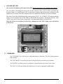
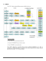
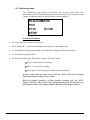

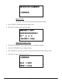

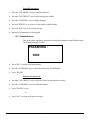

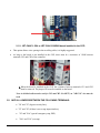
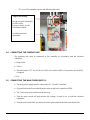


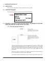
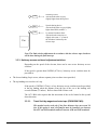
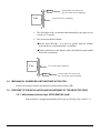
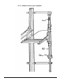

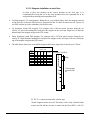
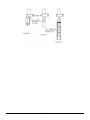
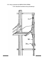
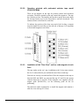

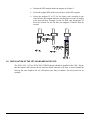
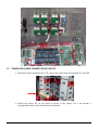
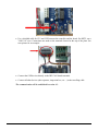


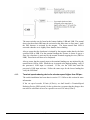

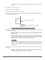

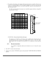


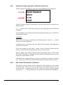

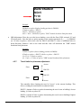

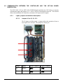

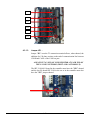
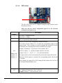

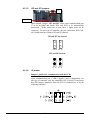
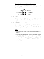
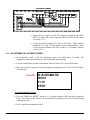


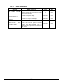
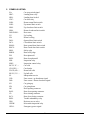
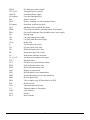
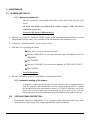

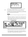


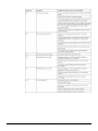
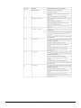

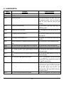
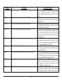


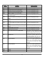
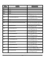
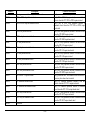
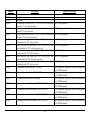
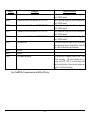


![EX MV MX3 User Manual [May16].vp](http://vs1.manualzilla.com/store/data/005646159_1-0d378a1c318c2dc00419aef6af60da73-150x150.png)