1
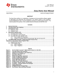
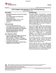
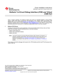
User's Guide
SWAU058C – December 2008 – Revised September 2015
Bluetooth Logger and Link Quality Monitor (LQM) Tools
This user's guide describes the TI Bluetooth debug tools used to trace log messages and protocol
transactions output from the TX_DBG pin of the WiLink™ connectivity devices. Consisting of the TI
Bluetooth Logger and associated plug-ins and the LQM, these tools provide visibility into the inner data
and states of the chip as well as information on remote device traffic. The architecture allows debugging of
both software and hardware error conditions and general optimization of operations.
Contents
Requirements ................................................................................................................ 3
1.1
System Requirements .............................................................................................. 3
1.2
Configuration Requirements ....................................................................................... 3
2
Installation .................................................................................................................... 3
3
TI Logger ...................................................................................................................... 4
3.1
Setting Up the TI Bluetooth Logger .............................................................................. 4
3.2
Logger Protocol Viewer ............................................................................................ 7
3.3
Logger Message Trace ........................................................................................... 10
3.4
Using the TI Logger Main Working Window ................................................................... 10
4
Link Quality Monitor ........................................................................................................ 13
4.1
Running the LQM.................................................................................................. 13
4.2
Using the LQM ..................................................................................................... 14
Appendix A
Terms and Abbreviations ......................................................................................... 20
1
List of Figures
1
Logger Icon ................................................................................................................... 3
2
LQM Icon...................................................................................................................... 3
3
Logger Main Working Window ............................................................................................. 4
4
Selecting Logger Settings
5
6
7
8
9
10
11
12
13
14
15
16
17
18
.................................................................................................. 5
Selecting a Port .............................................................................................................. 5
Criteria Dialog Box ........................................................................................................... 6
View Schemes Field ......................................................................................................... 7
Select View Dialog Box ..................................................................................................... 7
Selecting Logger Settings for Port Setup ................................................................................. 7
Selecting a Port in the Logger Settings Dialog Box ..................................................................... 8
Setup Dialog Box ............................................................................................................ 8
Squirt – Serial Port Settings ................................................................................................ 9
Basic Communications Diagram ........................................................................................... 9
Data Flow Direction in Main Working Window ......................................................................... 10
Log Levels ................................................................................................................... 10
Status Bar ................................................................................................................... 11
Bookmarks and Comments ............................................................................................... 12
Find Dialog Box ............................................................................................................. 12
WiLink is a trademark of Texas Instruments.
Bluetooth is a registered trademark of Bluetooth SIG, Inc.
FTDI Chip is a trademark of Future Technology Devices; International Limited.
Pentium is a registered trademark of Intel Corporation.
Windows is a registered trademark of Microsoft Corporation.
All other trademarks are the property of their respective owners.
SWAU058C – December 2008 – Revised September 2015
Submit Documentation Feedback
Bluetooth Logger and Link Quality Monitor (LQM) Tools
Copyright © 2008–2015, Texas Instruments Incorporated
1
www.ti.com
19
Starting the LQM ........................................................................................................... 13
20
LQM Main Window ......................................................................................................... 13
21
COM Port Selection ........................................................................................................ 14
22
Customize Dialog Box With Commands Tab Selected................................................................ 15
23
Customize Dialog Box With Toolbars Tab Selected ................................................................... 16
24
Customize Dialog Box With Keyboard Tab Selected .................................................................. 16
25
Customize Dialog Box With Menu Tab Selected....................................................................... 17
26
Customize Dialog Box With Options Tab Selected .................................................................... 17
27
LQM Active Window
28
29
.......................................................................................................
Increase Transmitted Power ..............................................................................................
Used-Channels Window ...................................................................................................
18
18
19
List of Tables
1
Logger Settings Dialog Box Functions .................................................................................... 5
2
Criteria Settings .............................................................................................................. 6
3
Export, Import, and Default Button Functions ............................................................................ 6
4
Editing Criteria Fields........................................................................................................ 6
5
Setup Dialog Box Functions ................................................................................................ 8
6
Icons Toolbar Functions ................................................................................................... 11
7
Status Bar Functions ....................................................................................................... 11
8
Keystroke Commands for Bookmarks and Comments
9
10
11
12
2
...............................................................
Find Dialog Box Functions ...............................................................................................
Menu Bar ....................................................................................................................
Toolbar .......................................................................................................................
Terms and Abbreviations ..................................................................................................
Bluetooth Logger and Link Quality Monitor (LQM) Tools
12
12
14
15
20
SWAU058C – December 2008 – Revised September 2015
Submit Documentation Feedback
Copyright © 2008–2015, Texas Instruments Incorporated
Requirements
www.ti.com
1
Requirements
1.1
System Requirements
The Bluetooth Logger and LQM requires the following hardware and software:
• PC running Pentium® II (minimum requirements)
• Operating systems: Windows® 2000, Windows XP, Windows 7
• Access to BT_UART_DBG pin
Debug and calibration tools for WLAN and Bluetooth® require four UART ports. The most efficient way to
drive these ports to the PC is to use a UART-to-USB converter (not included in the wireless tools
package). TI recommends using the WL18XXCOM82SDMMC adapter with the TI WL1837MODCOM8I
module or the TI WL1835MODCOM8B module on the COM8 board.
NOTE: Multiple UART to USB adapters are available on the market, such as the FTDI Chip™
development modules.
1.2
Configuration Requirements
The TI Bluetooth Logger and LQM applications for the WiLink 8 TI Bluetooth release require the latest ILI
configuration file.
NOTE: The ILI file supports all of the WiLink family and is based on the BTS naming format; for the
WL128x and prior releases, follow the guidelines in the README file.
The installation files are located in the directory named Wireless Tools at the installation path configured
during installation. By default, the files are located at the following path:
C:\Program Files (x86)\Texas Instruments\Wireless Tools
NOTE: Throughout this document, the directory in which the installation files reside is referred to as
Installation directory.
2
Installation
The Bluetooth Logger and LQM are part of the TI wireless tools package release. When the wireless tools
package is installed, the Logger and LQM icons are created in the Texas Instrument\Wireless Tools folder
at Start→Programs and on the desktop (see Figure 1 and Figure 2).
Figure 1. Logger Icon
Figure 2. LQM Icon
SWAU058C – December 2008 – Revised September 2015
Submit Documentation Feedback
Bluetooth Logger and Link Quality Monitor (LQM) Tools
Copyright © 2008–2015, Texas Instruments Incorporated
3
TI Logger
3
www.ti.com
TI Logger
The TI Bluetooth Logger traces log messages and monitors protocol transactions. The Logger records log
messages generated by the TI controller. The Logger consists of the following tools:
• Protocol Viewer: Embedded plug-in used to display the communication transactions between the
connected devices
• TI Island Message Trace: Embedded plug-in used to trace log messages generated by the TI
Bluetooth host controller
The TI Logger includes the following features:
• User-friendly, intuitive interface
• Logs traces with different importance levels
• Rich configuration options, including color tagging
After installation, use a UART-USB adapter to connect to the device.
3.1
Setting Up the TI Bluetooth Logger
To set up the TI Bluetooth Logger, perform the following steps:
1. Double-click the Logger icon to start the Logger application. The software initializes and displays the
main working window (see Figure 3).
Figure 3. Logger Main Working Window
2. From the menu bar of the main working window, click the View menu and select Settings, as shown in
Figure 4.
4
Bluetooth Logger and Link Quality Monitor (LQM) Tools
SWAU058C – December 2008 – Revised September 2015
Submit Documentation Feedback
Copyright © 2008–2015, Texas Instruments Incorporated
TI Logger
www.ti.com
Figure 4. Selecting Logger Settings
The Logger Settings dialog box displays (see Figure 5).
Figure 5. Selecting a Port
3. In the Installed Ports field of the Logger Settings dialog box, select a port from the list of ports. Figure 5
shows the Island1 plug-in selected.
Table 1 describes the functions of the Logger Settings dialog box buttons.
Table 1. Logger Settings Dialog Box Functions
Button
Function
Setup
Open the setup window
Duplicate
Duplicate the selected port to create a new instance of that port (enables
logging from different sources)
Delete
Delete the selected port
Apply
Apply the changes without closing the window
Cancel
Discard the changes and closes the window
OK
Save the new settings and closes the window
SWAU058C – December 2008 – Revised September 2015
Submit Documentation Feedback
Bluetooth Logger and Link Quality Monitor (LQM) Tools
Copyright © 2008–2015, Texas Instruments Incorporated
5
TI Logger
www.ti.com
4. Use criteria settings to differentiate between distinct logs. Figure 6 shows the Criteria dialog box.
Figure 6. Criteria Dialog Box
To set a criterion:
(a) Select a criteria type (see Table 2).
Table 2. Criteria Settings
Criteria Types
Function
View Filter
Select which logs to view and which to hide
Filter New Logs
Permanently delete all new logs on arrival that meet the set criteria
Critical
Define logs that are deemed critical
Tool
Run any external file or application when the appropriate new log arrives
Highlight Color
Highlight (with the selected color) any log meeting the set criteria
(b) Type the appropriate values in the text box.
Table 3 describes the functions of the Export, Import, and Default buttons.
Table 3. Export, Import, and Default Button Functions
Button
Function
Export
Export the current criteria settings to an external file
Import
Import a previously exported criteria file
Default
Clear all criteria values for the currently selected type
5. When selecting the criteria type (see Table 2), edit the text boxes described in Table 4.
Table 4. Editing Criteria Fields
Edit Box
6
Function
Log # (number)
Select the log number
Level
Select the level
Text
Enter the criteria data
Bluetooth Logger and Link Quality Monitor (LQM) Tools
SWAU058C – December 2008 – Revised September 2015
Submit Documentation Feedback
Copyright © 2008–2015, Texas Instruments Incorporated
TI Logger
www.ti.com
6. To create (and later select) multiple schemes or delete existing schemes, use the View Schemes field
of the Criteria dialog box (see Figure 7).
Figure 7. View Schemes Field
(a) After creating a new view scheme, click Save As (see Figure 7). The Select View dialog box
displays (see Figure 8).
Figure 8. Select View Dialog Box
(b) In the Name field, type a scheme name and click the OK button.
3.2
Logger Protocol Viewer
The TI Protocol Viewer is a plug-in embedded in the Logger application that displays communication
transactions between the master and slave devices connected to the network. The main screen is easy to
use and intuitive for the new user. The Tool Tips feature describes all headings and toolbars whenever the
cursor moves over them. The columns can be dragged and dropped as desired, and the data types can
be changed to various colors to make the displayed data easier to read.
3.2.1
Setting Up the Protocol Viewer
To set up the Protocol Viewer, perform the following steps:
1. From the Logger window menu bar, click the View menu and select Settings (see Figure 9).
Figure 9. Selecting Logger Settings for Port Setup
The Logger Settings dialog box displays (see Figure 10).
SWAU058C – December 2008 – Revised September 2015
Submit Documentation Feedback
Bluetooth Logger and Link Quality Monitor (LQM) Tools
Copyright © 2008–2015, Texas Instruments Incorporated
7
TI Logger
www.ti.com
Figure 10. Selecting a Port in the Logger Settings Dialog Box
2. In the Installed Ports field, select the check box of the port to activate (for example, ProtView 1) for the
Protocol Viewer. The Setup dialog box displays (see Figure 11).
Figure 11. Setup Dialog Box
NOTE: If the Setup dialog box does not open, click the Setup button on the Logger Settings dialog
box.
Table 5 lists the functions of the Setup dialog box.
Table 5. Setup Dialog Box Functions
Button
8
Function
Setup
Open the port setup dialog box
Add File
Add a new .xml file that defines the HCI library containing the HCI
command set
Remove
Remove files from the Mapping window
Scan Folder
N/A
Export
N/A
Cancel
Discard changes and closes the window
OK
Save the new settings and closes the window
Bluetooth Logger and Link Quality Monitor (LQM) Tools
SWAU058C – December 2008 – Revised September 2015
Submit Documentation Feedback
Copyright © 2008–2015, Texas Instruments Incorporated
TI Logger
www.ti.com
3. Select a port from the Port drop-down menu.
4. To verify or change the port settings, click the Setup button. The Squirt – Serial Port Settings dialog
box displays (see Figure 12).
Figure 12. Squirt – Serial Port Settings
5. From the Set Baud Rate drop-down menu, select the baud rate of 921600 and click the OK button.
NOTE: HCI commands are not logged if the ProtView is not set.
3.2.2
Basic Operation Scenario of the Protocol Viewer
As shown in Figure 13, each device combination represents a local host and a remote device. The device
communicates using link-manager protocol (LMP) transactions. Each device uses the host controller
interface (HCI) protocol to communicate internally between the host and the connected device. All
communication transactions appear in sequence in the relevant columns on the protocol viewer screen.
Device
Host controller
interface (HCI)
Slave
(remote device)
Host
Device
Link manager
protocol (LMP)
Host
Slave
(remote device)
Master
Device
Host
Slave
(remote device)
Device
Host
wau058-012
Figure 13. Basic Communications Diagram
SWAU058C – December 2008 – Revised September 2015
Submit Documentation Feedback
Bluetooth Logger and Link Quality Monitor (LQM) Tools
Copyright © 2008–2015, Texas Instruments Incorporated
9
TI Logger
3.2.3
www.ti.com
Using the Protocol Viewer
Open a second instance of the Logger main working window. The status bar displays the Protocol Viewer
(ProtView). If the status bar does not display ProtView, correct the port setup (for more information on port
setup, see Section 3.2.1, Setting Up the Protocol Viewer).
The host communicates with the local device using HCI protocol transactions. The local device and the
remote devices communicate using LMP transactions. Figure 14 shows the direction of the data flow.
Figure 14. Data Flow Direction in Main Working Window
For more information on the Protocol Viewer, see the Bluetooth Specification.
3.3
Logger Message Trace
The TI Island Message Trace is a plug-in embedded in the Logger application that traces log messages
generated by the TI Bluetooth host controller. The TI Island Message Trace offers a user-friendly, intuitive
interface with rich configuration options, including color tagging, and logs traces with different importance
levels.
3.4
Using the TI Logger Main Working Window
3.4.1
Toggling Log Levels
Each log has a specific level that can be toggled on and off as follows (see Figure 15):
Figure 15. Log Levels
•
•
3.4.2
To select or deselect levels, use the right-click menu.
To select a desired level, press the Ctrl key and click the level button.
Using the Toolbar Options
Table 6 describes the functions of the icons toolbar in the Logger main working window.
10
Bluetooth Logger and Link Quality Monitor (LQM) Tools
SWAU058C – December 2008 – Revised September 2015
Submit Documentation Feedback
Copyright © 2008–2015, Texas Instruments Incorporated
TI Logger
www.ti.com
Table 6. Icons Toolbar Functions
Icon
Function
Open new screen (Ctrl+N)
Save screen (Ctrl+S)
Open file (Ctrl+O)
When the log reaches a predetermined size, the logs are automatically saved and the log buffer is cleared.
Delete messages (DEL)
Copy messages (Ctrl+C)
Show or hide the date (toggles)
Show or hide the time (toggles)
Show or hide the relative time (toggles)
Open the settings window
Toggle automatic scrolling
Audio beep on critical alarm (toggles)
Mute critical alarm
3.4.2.1
Status Bar
Figure 16 shows the status bar.
Figure 16. Status Bar
Table 7 describes the functions of the status bar.
Table 7. Status Bar Functions
Name
Function
Selected port and connection names
Display the selected port and connection names
Auto Save
Automatically save at a predetermined time duration
Currently selected view scheme
View
Clicking on this pane enables toggling between view schemes.
Ctrl+Tab switches to previous view schemes.
Ctrl+0..9 switches to a specific view scheme.
Logs: <Visible>/<Total>
Indicate how many visible logs are currently displayed
SWAU058C – December 2008 – Revised September 2015
Submit Documentation Feedback
Bluetooth Logger and Link Quality Monitor (LQM) Tools
Copyright © 2008–2015, Texas Instruments Incorporated
11
TI Logger
3.4.2.2
www.ti.com
Bookmarks and Comments
The Bookmarks/Comments menu contains bookmark and comment commands.
• To add or edit comments or toggle bookmarks on and off, right-click the popup menu.
• All comments and bookmarks are automatically saved when the logs are saved to file.
Figure 17 shows the placement of the bookmark and comment icons on the main working window.
Figure 17. Bookmarks and Comments
Table 8 lists the keystroke commands to select and toggle bookmarks and edit comments.
Table 8. Keystroke Commands for Bookmarks and
Comments
Keystroke
Command
3.4.2.3
Function
F2
Next bookmark
Ctrl+F2
Toggle bookmark
Enter
Edit comment
Find Function
Figure 18 shows the Find dialog box. To display the Find dialog box, press Ctrl+F.
Figure 18. Find Dialog Box
Table 9 lists the functions of the Find dialog box.
Table 9. Find Dialog Box Functions
Ctrl+F
12
Find Dialog Box
F3
Find next
1..9
Find next level
A..Z
Incremental search
Bluetooth Logger and Link Quality Monitor (LQM) Tools
SWAU058C – December 2008 – Revised September 2015
Submit Documentation Feedback
Copyright © 2008–2015, Texas Instruments Incorporated
Link Quality Monitor
www.ti.com
4
Link Quality Monitor
The Bluetooth Link Quality Monitor (LQM) application monitors the received signal strength indication
(RSSI) and the link quality (averaged throughput) information during a connection in runtime.
4.1
Running the LQM
1. To start the LQM, click the Link Quality Monitor program icon (see Figure 19).
Figure 19. Starting the LQM
2. The LQM main window displays with the following panes (see Figure 20):
• RSSI pane
• Throughput pane
• Used-channel pane (Bluetooth and BLE)
Figure 20. LQM Main Window
3. To select the port:
(a) From the toolbar, click the port connection box. A drop-down menu displays the available ports (see
SWAU058C – December 2008 – Revised September 2015
Submit Documentation Feedback
Bluetooth Logger and Link Quality Monitor (LQM) Tools
Copyright © 2008–2015, Texas Instruments Incorporated
13
Link Quality Monitor
www.ti.com
Figure 21).
(b) Select the desired port. (The COM port uses the following default configuration: baud = 115200, flow
control = none, 8-bit data byte without parity check, and 1 stop bit.)
Figure 21. COM Port Selection
4.2
4.2.1
Using the LQM
Menu Bar
Table 10 describes the menu bar menus and submenus.
Table 10. Menu Bar
Menu
File
View
Submenu
New
Create a new LQM file
Open
Open an existing LQM file
Save
Save the active LQM file
Save as
Save the active LQM file with a new name
Exit
Exit the LQM application
Chart throughput results
Display or hide chart throughput results
AFH Master
Display or hide the AFH Master Piconet pane
BLE AFH master
Display or hide the BLE AFH Master Piconet pane
BLE AFH Slave
Display or hide the BLE AFH Slave Piconet pane
AFH Slave 1 Piconet
Display or hide the AFH Slave 1 Piconet pane
AFH Slave 2 Piconet
Display or hide the AFH Slave 2 Piconet pane
Standard toolbar
Display or hide the standard toolbar
Status bar
Display or hide the status bar
Customize
Customize the keyboard and toolbar
Help
4.2.2
Function
LQM information and version number
Toolbar
Table 11 describes the toolbar options.
14
Bluetooth Logger and Link Quality Monitor (LQM) Tools
SWAU058C – December 2008 – Revised September 2015
Submit Documentation Feedback
Copyright © 2008–2015, Texas Instruments Incorporated
Link Quality Monitor
www.ti.com
Table 11. Toolbar
Item
Function
Create a new LQM file
Open an existing LQM file
Save the active LQM file with a new name
Select the port to configure the connection between the application and the device
Port connection box
4.2.3
Customize Dialog Box
To open the customize dialog box, click the View menu and select Customize. The Customize dialog box
with the following tabs (see Figure 22):
• Commands
• Toolbars
• Keyboard
• Menu
• Options
Use the Commands tab to drag and drop commands from the Customize dialog box to the menu or
toolbars (see Figure 22).
Figure 22. Customize Dialog Box With Commands Tab Selected
Use the Toolbars tab to enable and disable toolbars (see Figure 23).
SWAU058C – December 2008 – Revised September 2015
Submit Documentation Feedback
Bluetooth Logger and Link Quality Monitor (LQM) Tools
Copyright © 2008–2015, Texas Instruments Incorporated
15
Link Quality Monitor
www.ti.com
Figure 23. Customize Dialog Box With Toolbars Tab Selected
Use the Keyboard tab to create a keyboard shortcut for each menu item (see Figure 24).
Figure 24. Customize Dialog Box With Keyboard Tab Selected
Use the Menu tab to customize menus, which includes animations and shadows (see Figure 25).
16
Bluetooth Logger and Link Quality Monitor (LQM) Tools
SWAU058C – December 2008 – Revised September 2015
Submit Documentation Feedback
Copyright © 2008–2015, Texas Instruments Incorporated
Link Quality Monitor
www.ti.com
Figure 25. Customize Dialog Box With Menu Tab Selected
Use the Options tab to customize how menus are viewed (see Figure 26).
Figure 26. Customize Dialog Box With Options Tab Selected
4.2.4
LQM Active Window
The LQM active window displays the following kinds of data regarding the quality of the link (also
Figure 27):
• RSSI
• Used channels map
SWAU058C – December 2008 – Revised September 2015
Submit Documentation Feedback
Bluetooth Logger and Link Quality Monitor (LQM) Tools
Copyright © 2008–2015, Texas Instruments Incorporated
17
Link Quality Monitor
www.ti.com
Figure 27. LQM Active Window
The LQM application supports up to seven handles and three piconets (one master and two slaves).
4.2.4.1
RSSI Window
The RSSI window displays the RSSI measurements of up to seven handles. Each handle is represented
by a color. The scale of the window varies from 0[dbm] to –90[dbm]. The increase threshold is -65[dbm],
and the decrease threshold is –45[dbm].
Figure 28. Increase Transmitted Power
18
Bluetooth Logger and Link Quality Monitor (LQM) Tools
SWAU058C – December 2008 – Revised September 2015
Submit Documentation Feedback
Copyright © 2008–2015, Texas Instruments Incorporated
Link Quality Monitor
www.ti.com
Each time the measured RSSI falls below the lower threshold, the device sends a request to the
transmitting device to increase the transmitted power to within the desired range (see Figure 28). In this
case, ↑ (up arrow symbol) indicates (in the same color of the specific handle) that transmitted power must
increase. When the transmitted power rises above the upper threshold, ↓ (down arrow symbol) indicates
that transmitted power must decrease.
The last throughput results sample is displayed near the related graph. Green text indicates enough
samples are present for statistics; red text indicates not enough samples are present for statistics.
4.2.4.2
Used-Channels Window
The Used-Channels window includes up to three channel maps and up to two piconets (a device can be a
master in one piconet and a slave in two other piconets).
Channels appear as decimal values from 0 to 78 (for example, channel 0 = 2402 MHz;
channel 1 = 2403 MHz).
The following colors can represent each channel:
• Light gray: the specific channel is not in use.
• Dark gray: the specific channel is recently removed.
• Blue: the specific channel is recently added.
• Black: the specific channel is in use.
Figure 29 shows the used-channels window.
Figure 29. Used-Channels Window
SWAU058C – December 2008 – Revised September 2015
Submit Documentation Feedback
Bluetooth Logger and Link Quality Monitor (LQM) Tools
Copyright © 2008–2015, Texas Instruments Incorporated
19
Appendix A
SWAU058C – December 2008 – Revised September 2015
Terms and Abbreviations
Table 12 lists terms and abbreviations.
Table 12. Terms and Abbreviations
Term
20
Description
BD_ADDR
Bluetooth device address
BER
Bit error rate
BT
Bluetooth
HCI
Host controller interface
Host/host PC
A PC connected to the device through the serial port
LMP
Link manager protocol
LQM
Link quality monitor
PER
Packet error rate
RF
Radio frequency
RSSI
Received signal strength indication
SW
Software
VS
Vendor-specific
Terms and Abbreviations
SWAU058C – December 2008 – Revised September 2015
Submit Documentation Feedback
Copyright © 2008–2015, Texas Instruments Incorporated
Revision History
www.ti.com
Revision History
Changes from B Revision (March 2011) to C Revision .................................................................................................. Page
•
•
•
•
•
•
•
•
•
•
•
Changed user guide title from TX_DBG Software Tools User Manual............................................................. 1
Changed organization of user's guide .................................................................................................. 1
Added Section 2, Installation ............................................................................................................ 3
Changed Figure 3 ......................................................................................................................... 4
Changed Figure 4 ......................................................................................................................... 5
Changed Figure 9 ......................................................................................................................... 7
Changed Figure 14 ...................................................................................................................... 10
Deleted section on PC Setup for Near Field Communications (NFC) ............................................................ 13
Changed Section 4.1, Installing the LQM............................................................................................. 13
Deleted section on PER/BER window ................................................................................................ 19
Added Appendix A, Terms and Abbreviations ....................................................................................... 20
SWAU058C – December 2008 – Revised September 2015
Submit Documentation Feedback
Copyright © 2008–2015, Texas Instruments Incorporated
Revision History
21
IMPORTANT NOTICE
Texas Instruments Incorporated and its subsidiaries (TI) reserve the right to make corrections, enhancements, improvements and other
changes to its semiconductor products and services per JESD46, latest issue, and to discontinue any product or service per JESD48, latest
issue. Buyers should obtain the latest relevant information before placing orders and should verify that such information is current and
complete. All semiconductor products (also referred to herein as “components”) are sold subject to TI’s terms and conditions of sale
supplied at the time of order acknowledgment.
TI warrants performance of its components to the specifications applicable at the time of sale, in accordance with the warranty in TI’s terms
and conditions of sale of semiconductor products. Testing and other quality control techniques are used to the extent TI deems necessary
to support this warranty. Except where mandated by applicable law, testing of all parameters of each component is not necessarily
performed.
TI assumes no liability for applications assistance or the design of Buyers’ products. Buyers are responsible for their products and
applications using TI components. To minimize the risks associated with Buyers’ products and applications, Buyers should provide
adequate design and operating safeguards.
TI does not warrant or represent that any license, either express or implied, is granted under any patent right, copyright, mask work right, or
other intellectual property right relating to any combination, machine, or process in which TI components or services are used. Information
published by TI regarding third-party products or services does not constitute a license to use such products or services or a warranty or
endorsement thereof. Use of such information may require a license from a third party under the patents or other intellectual property of the
third party, or a license from TI under the patents or other intellectual property of TI.
Reproduction of significant portions of TI information in TI data books or data sheets is permissible only if reproduction is without alteration
and is accompanied by all associated warranties, conditions, limitations, and notices. TI is not responsible or liable for such altered
documentation. Information of third parties may be subject to additional restrictions.
Resale of TI components or services with statements different from or beyond the parameters stated by TI for that component or service
voids all express and any implied warranties for the associated TI component or service and is an unfair and deceptive business practice.
TI is not responsible or liable for any such statements.
Buyer acknowledges and agrees that it is solely responsible for compliance with all legal, regulatory and safety-related requirements
concerning its products, and any use of TI components in its applications, notwithstanding any applications-related information or support
that may be provided by TI. Buyer represents and agrees that it has all the necessary expertise to create and implement safeguards which
anticipate dangerous consequences of failures, monitor failures and their consequences, lessen the likelihood of failures that might cause
harm and take appropriate remedial actions. Buyer will fully indemnify TI and its representatives against any damages arising out of the use
of any TI components in safety-critical applications.
In some cases, TI components may be promoted specifically to facilitate safety-related applications. With such components, TI’s goal is to
help enable customers to design and create their own end-product solutions that meet applicable functional safety standards and
requirements. Nonetheless, such components are subject to these terms.
No TI components are authorized for use in FDA Class III (or similar life-critical medical equipment) unless authorized officers of the parties
have executed a special agreement specifically governing such use.
Only those TI components which TI has specifically designated as military grade or “enhanced plastic” are designed and intended for use in
military/aerospace applications or environments. Buyer acknowledges and agrees that any military or aerospace use of TI components
which have not been so designated is solely at the Buyer's risk, and that Buyer is solely responsible for compliance with all legal and
regulatory requirements in connection with such use.
TI has specifically designated certain components as meeting ISO/TS16949 requirements, mainly for automotive use. In any case of use of
non-designated products, TI will not be responsible for any failure to meet ISO/TS16949.
Products
Applications
Audio
www.ti.com/audio
Automotive and Transportation
www.ti.com/automotive
Amplifiers
amplifier.ti.com
Communications and Telecom
www.ti.com/communications
Data Converters
dataconverter.ti.com
Computers and Peripherals
www.ti.com/computers
DLP® Products
www.dlp.com
Consumer Electronics
www.ti.com/consumer-apps
DSP
dsp.ti.com
Energy and Lighting
www.ti.com/energy
Clocks and Timers
www.ti.com/clocks
Industrial
www.ti.com/industrial
Interface
interface.ti.com
Medical
www.ti.com/medical
Logic
logic.ti.com
Security
www.ti.com/security
Power Mgmt
power.ti.com
Space, Avionics and Defense
www.ti.com/space-avionics-defense
Microcontrollers
microcontroller.ti.com
Video and Imaging
www.ti.com/video
RFID
www.ti-rfid.com
OMAP Applications Processors
www.ti.com/omap
TI E2E Community
e2e.ti.com
Wireless Connectivity
www.ti.com/wirelessconnectivity
Mailing Address: Texas Instruments, Post Office Box 655303, Dallas, Texas 75265
Copyright © 2015, Texas Instruments Incorporated