1
User Manual
SLAU645 – June 2015
Easy Demo User Manual
Jorge Arbona
Audio and Imaging Products
ABSTRACT
The Easy Demo platform is a combination of hardware and microcontroller software capable
of self-booting and performing A/B comparisons. The newest revision of the PurePath™
Console Motherboard, Rev F, has the hardware necessary to perform these functions. This
manual explains the operation of the available reference hardware and MSP430 code.
Contents
1
General Overview ......................................................................................................................... 3
2
The Easy Demo User Interface .................................................................................................... 4
3
Development Tools ...................................................................................................................... 5
3.1 Hardware Tools ...................................................................................................................... 5
3.2 Software Tools........................................................................................................................ 5
4
Easy Demo Sample Code ............................................................................................................ 6
4.1 The Easy Demo Project .......................................................................................................... 8
4.2 The Application Layer (/Device) .............................................................................................. 9
4.3 The Audio API Layer (/AUDIO_API) ..................................................................................... 10
4.3.1 Audio Header File Generation ................................................................................... 11
4.3.2 Loading a PurePath Studio/Console Header File into the Audio API ......................... 11
5
TLV320AIC3262 PurePath™ Studio Example Process Flow ................................................... 13
Appendix A. Easy Demo Virtual Register Map ................................................................................. 14
A.1 Register Map Summary ........................................................................................................ 15
A.2 Virtual Register Map ............................................................................................................. 16
A.2.1 Page 0 Registers....................................................................................................... 16
A.2.2 Page 1 Registers....................................................................................................... 19
Figure 1.
Figure 2.
Figure 3.
Figure 4.
Figure 5.
Figure 6.
Figure 7.
Figure 8.
Figure 9.
Figure 10.
Figure 11.
Figure 12.
Figure 13.
Figure 14.
Figure 15.
Figures
The PurePath Console™ Motherboard (shown on the left) .......................................... 3
The Easy Demo User Interface ....................................................................................... 4
Software and Hardware Layer Stack-up ......................................................................... 6
Hardware Layer Stack-up ................................................................................................ 7
Easy Demo Project .......................................................................................................... 8
Project Configuration Selection ..................................................................................... 8
Project Configuration Selection ..................................................................................... 8
Event Handler State Machine .......................................................................................... 9
Audio API Folder Structure ........................................................................................... 10
Header Parser Folder Structure .................................................................................... 11
PurePath™ Studio Header File Example ...................................................................... 12
PurePath™ Console Header File Example ................................................................... 12
Audio Signal Flow .......................................................................................................... 13
PPCMB AIC3262 Process Flow ..................................................................................... 13
Set Volume, Input and Mode Example.......................................................................... 14
1
SLAU645
Table 1.
Table 2.
2
Tables
Example Demo Layout .................................................................................................... 4
Easy Demo Virtual Register Map Summary ................................................................. 15
Easy Demo User Manual
SLAU645
1
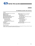
General Overview
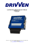
The Easy Demo platform is a simple way to perform quick demos using its on-board user
interface. The newest revision of the PurePath™ Console Motherboard (PPCMB), Rev F, adds
self-booting capabilities and this user interface to easily perform A/B comparisons. The PPCMB
is already compatible with many of TI’s audio evaluation modules (EVMs), making it a great
choice for the Easy Demo platform. The Easy Demo push-button user interface is described in
Chapter 2.
Figure 1.
The PurePath Console™ Motherboard (Shown on the Left)
Chapter 3 lists the hardware and software tools necessary for development.
Chapter 4 describes the Easy Demo sample code.
Chapter 5 describes the TLV320AIC3262 signal processing flow.
Easy Demo User Manual
3
SLAU645
2
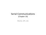
The Easy Demo User Interface
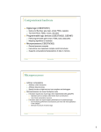
The Easy Demo User Interface (UI) has several push-buttons and LEDs to easily perform A/B
comparisons.
To activate the User Interface and begin the self-boot process, simply push any UI button. This
will give the MSP430 control of the DUT I2C bus.
USER INTERFACE
A
A
B
B
PROFILE
MODE
Figure 2.
USB
OPTICAL
VOL
ANALOG
INPUT
The Easy Demo User Interface
The User Interface consists of:
1. A Profile is meant to hold different demos. For example, Profile A might be a stereo
enhancement demo, while Profile B might be a bass boost demo.
2. Within each Profile, there are Modes. Each Mode is meant to change an option within a
Profile. For example, if performing a stereo enhancement demo, Mode A is bypass and
Mode B enables the enhancement.
Table 1.
Profile
A
B
Example Demo Layout
Profile Name
Stereo Enhancement
Bass Boost
Mode
Mode Name
A
Disabled
B
Enabled
A
Disabled
B
Enabled
3. The Volume button (VOL) controls the volume level of the system. The volume range
can be defined by the user.
4. The Input button selects between PPCMB input sources: USB, Optical and Analog.
The Easy Demo UI can also be controlled remotely via USB or an external
I2C interface by sending simple I2C commands.
4
Easy Demo User Manual
SLAU645
3
Development Tools
This section covers the recommended hardware and software tools for development.
3.1
Hardware Tools
A list of the recommended hardware collateral follows:
3.2
•
PurePath™ Console Motherboard (PPCMB) – Can be
obtained here: http://www.ti.com/tool/purepath-cmbevm. A
PPCMB-compatible EVM is needed to perform demos.
•
eZ430 USB Debugging Interface – Older versions are not
compatible with the MSP430F5510 on-board the PPCMB. The
eZ430 Chronos has the latest version and can be obtained here:
http://www.ti.com/tool/EZ430-CHRONOS
•
MSP-FET Flash Emulation Tool (optional) – Requires
hand-wiring Spy-Bi-Wire connections between the
debugger and the PPCMB. Can be obtained here:
http://www.ti.com/tool/msp-fet430uif
Software Tools
A list of recommended tools to download before starting evaluation follows:
•
Code Composer Studio – for MSP430 firmware debugging and
programming. Download here: http://www.ti.com/tool/ccstudio.
•
PurePath™ Studio GDE (Portable Audio) – generates and
downloads miniDSP code into the on-board TLV320AIC3262.
Download here: http://www.ti.com/tool/aicpurepath_studio.
•
PurePath™ Console – generates and downloads miniDSP code to
EVM boards connected to the PPCMB. Download here:
http://www.ti.com/tool/PUREPATHCONSOLE.
Easy Demo User Manual
5
SLAU645
4
Easy Demo Sample Code
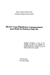
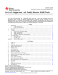
The Easy Demo sample code handles the user interface and sends I2C/SPI commands to onboard peripherals and EVM connected to the PurePath™ Console Motherboard. The code is
divided into 3 software layers:
1. The Application layer contains the main event handler, initialization code, interrupt
service routines (ISRs) for port interrupts, and so forth.
2. The API layer contains the Audio API which handles the configuration of the audio
devices for each profile, mode, volume, and input selection.
3. The Driver layer translates the audio commands into I2C and SPI commands. It also
implements low-level functions such as delays and the I2C slave interface.
Application Layer
Application Code (/Device)
API Layer
Audio API (/AUDIO_API)
aic3262.c, tas5766.c, etc.
Driver Layer
(/Drivers)
MSP430
Hardware
spi.c
i2c.c
vrm.c
SPI Master
(USCI_A0)
I2C Master
(USCI_B0)
I2C Slave
(USCI_B1)
Px.x
Storage
Px.x
microSD Card
USB
I2C Master
4Mbit Flash
512kbit EEPROM
DUT
PurePath™
Console
Motherboard
User Interface
(Buttons / LEDs)
Figure 3.
6
I/O Pins
Px.x
Software and Hardware Layer Stack-up
Easy Demo User Manual
SLAU645
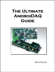
The PPCMB has an MSP430F5510 microcontroller to perform the self-booting and user
interface tasks. It also has 4 methods to store data: MSP430 flash, on-board I2C EEPROM, onboard SPI flash, and an SPI microSD card slot. Currently, the MSP430 flash and I2C EEPROM
are the only methods being used.
MSP430
Hardware
SPI Master
(USCI_A0)
I2C Master
(USCI_B0)
I2C Slave
(USCI_B1)
I/O Pins
Px.x
Storage
Px.x
microSD Card
USB
I2C Master
4Mbit Flash
512kbit EEPROM
DUT
PurePath™
Console
Motherboard
User Interface
(Buttons / LEDs)
Figure 4.
Px.x
Hardware Layer Stack-up
The Easy Demo code has a Virtual Register Map (VRM) that is controlled by the Application
layer or the I2C Slave port. The I2C Slave port allows configuring the User Interface via USB or
remotely without having to use the on-board User Interface. This is handled in /Device/vrm.c.
Additional details can be found in Appendix A. Note that the Virtual Register Map is stored in the
first few registers of the I2C EEPROM.
The DUT can be controlled via I2C by the on-board TAS1020B USB controller or the
MSP430F5510. To prevent I2C contention issues, the bus is multiplexed and controlled by a
GPIO pin (see Figure 4). As mentioned in Chapter 2, the MSP430 waits for the user to push a UI
button to begin initialization. This will give the MSP430 control of the DUT I2C bus. DUT control
can return to the TAS1020B or external interface by sending 0x01 to the VRM Register 1.
Pushing the on-board Reset button will also return DUT control back to the TAS1020B or
external interface.
Easy Demo User Manual
7
SLAU645
4.1
The Easy Demo Project
The folder structure is quite simple. The execution begins in main.c. The 3 software layers are
organized in folders: Device, AUDIO_API, and Drivers. The changelog.txt file provides a list of
changes from previous revisions. The rest of the files and folders are automatically generated by
the Code Composer Studio compiler.
Figure 5.
Easy Demo Project
For the PPCMB, select PPCMB_REVx under Properties > CCS General. This selects the
MSP430F5510 as the MCU.
Figure 6.
Project Configuration Selection
The PPCMB_REVx also sets the __PPCMB_REVF__ flag under Properties > C/C++ General >
Paths and Symbols. This symbol is used throughout the project to identify the configuration.
Figure 7.
8
Easy Demo User Manual
Project Configuration Selection
SLAU645
4.2
The Application Layer (/Device)
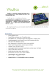
The Application code uses an event-driven architecture. The event handler can be found in
Device/Device_eventHandler.c. Its state machine is shown in Figure 8. Text in capital letters
indicates states. Each state will call an output function upon entry. Before exiting the state, flags
(in blue) will be set for other states to perform actions.
START
LPM3
INIT
out: init()
vrm_chg
reset = 0
reset = 1
Active
RESET
out: reset()
IDLE
out: idle()
POST
SERVICE
out:
post_service()
1
PRE
SERVICE
out:
pre_service()
reset_chg
2
usb_active_chg
ppcmb_init
PPCMB_INIT
out:
ppcmb_init()
profile_chg
input_chg
USB_ACTIVE
out:
usb_active()
local_chg
SERVICE
out: service()
profile_chg
7
3
UPDATE
LEDS
out:
update_leds()
vol_chg
PROFILE
out: profile()
local_chg
mode_chg
mode_chg
input_chg
6
4
VOLUME
out: volume()
local_chg
5
MODE
out: mode()
local_chg
vol_chg
Service
Priority
Figure 8.
INPUT
out: input()
local_chg
vol_chg
Event Handler State Machine
Easy Demo User Manual
9
SLAU645
4.3
The Audio API Layer (/AUDIO_API)
The Audio API makes loading audio device configurations easy. The Application Layer simply
needs to call a function with a parameter and value. For example, if it is desired to change the
volume, simply send the following command.
Audio(AUDIO_VOLUME, &Device.status.volume);
The second parameter passes the address of a volume variable.
Note that the second parameter is of type void *, therefore, any type is compatible with the
Audio() function. The advantage of this approach is that the Audio API can change the volume at
the Application Layer in case the value exceeds the maximum level specified in the Audio API.
The Application Layer should only have access to AUDIO_API/Audio.h.
The AUDIO_API is structured to support any parser type (for example, EEPROM, header,
sdcard, and so forth). However, loading scripts from a header file is the only method that has
been implemented at this moment.
Figure 9.
10
Easy Demo User Manual
Audio API Folder Structure
SLAU645
4.3.1 Audio Header File Generation
The Audio API currently parses header files that originate from PurePath™ Studio GDE and
PurePath™ Console software. Refer to the documentation of each software tool for details.
The miniDSP code for the on-board TLV320AIC3262 chip is already included as part of the
project. It does not need to be modified. The PurePath™ Studio process flow that was used to
generate that code is explained in Chapter 5.
4.3.2 Loading a PurePath Studio/Console Header File into the Audio API
The AUDIO_API/header folder of the MSP430 code contains custom miniDSP header files.
Once the code is compiled, the header file data should be pasted in xxxxx_x_code.h. This
header file usually contains the default configuration that is loaded when a Profile is selected.
Figure 10. Header Parser Folder Structure
The xxxxx_x_configs.h files contain configurations such as coefficients for A/B comparison,
sleep, wake, and other commands. This header file usually contains the configurations loaded
when a Mode is selected.
Small changes need to be done to the PurePath Studio/Console output header file when
integrating into the MSP430 code:
1. Header guards should be added.
2. The header_parser.h file should be included.
3. The cfg_reg/reg_value name should be re-defined to be const so it is loaded into the
MSP430 ROM and not RAM.
Easy Demo User Manual
11
SLAU645
A PurePath™ Studio example is shown in Figure 11:
// (c)2015 by Texas Instruments Incorporated, All Rights Reserved.
#ifndef AIC3262_1_CODE_H_
#define AIC3262_1_CODE_H_
#include "../header_parser.h"
#define cfg_reg static const cfg_reg
#define reg_value cfg_reg
reg_value REG_Section_program[] = {
{ 0,0x0},
{ 0x7F,0x00},
{121,0x01},
{ 1,0x01},
{254,0x01},
{ 0x7F,0x78},
...
...
};
#endif /* AIC3262_1_CODE_H_ */
Figure 11. PurePath™ Studio Header File Example
Figure 12 shows a PurePath™ Console Example:
// (c)2015 by Texas Instruments Incorporated, All Rights Reserved.
#ifndef TAS5766M_1_CODE_H_
#define TAS5766M_1_CODE_H_
#include "../header_parser.h"
#define cfg_reg static const cfg_reg
#define reg_value cfg_reg
// Paste PurePath Console generated configuration here:
cfg_reg registers[] = {
// Select Page 0
{ 0x00, 0x00 },
// Set the device into Powerdown
{ 0x02, 0x11 },
// Reset Device
{ 0x01, 0x11 },
...
...
};
#endif /* TAS5766M_1_CODE_H_ */
Figure 12. PurePath™ Console Header File Example
12
Easy Demo User Manual
SLAU645
5
TLV320AIC3262 PurePath™ Studio Example Process Flow
In the PurePath™ Console Motherboard, audio can be sourced from USB, Optical, or Analog.
This signal is then fed to the TLV320AIC3262 Audio Codec with miniDSP. The codec then sends
a digital signal to the target EVM via I2S and an analog signal to the HP OUT audio jack. Refer to
the schematics for details (Rev F+).
Source
(USB, Optical or Analog)
Target EVM
TLV320AIC3262
Headphones
Figure 13. Audio Signal Flow
The PurePath™ Studio process flow shows such implementation. For cases where it is desired
to limit the main volume (for example, to protect a speaker based on power level), the Limit_1
component can be adjusted relative to full-scale. Volume is controlled indirectly using the
Main_Vol_1 component. 0 dB is obtained by writing 0x400000.
Figure 14. PPCMB AIC3262 Process Flow
Easy Demo User Manual
13
SLAU645
Appendix A. Easy Demo Virtual Register Map
The Easy Demo Virtual Register Map (VRM) contains 128 pages of 8-bit registers. Each register
corresponds to an on-board 64kB (512kbit) EEPROM memory location. The external I2C master
sends I2C commands through USCI_B1 to program these virtual registers.
The device can be controlled by writing to certain locations in Page 0 and Page 1 of the VRM.
Figure 15 is an example command that can be sent through I2C by the host PC.
w
d
w
d
w
d
w
d
w
d
w
d
w
d
w
30 02
500
30 02
500
30 02
500
30 02
500
30 02
500
30 02
500
30 03
500
30 03
01 # Increment Mode
02 # Increment Audio Input Source
04 # Increment Volume+
08 # Increment Volume10 # Increment Profile+
1F # Increment All
01 # Set Profile to 1
00 # Set Profile to 0
Figure 15. Set Volume, Input, and Mode Example
The I2C Write Protocol
[S][I2C Slave Address/W][ACK][Register Offset][ACK][Data(0)][ACK]...[Data(n)][ACK][P]
The I2C master must perform ACK polling to allow the MSP430 time to process its data after
each write. To perform ACK polling, send the I2C slave address along with a write command. If
a NACK is returned as in the following, then issue a stop command (P).
[S][I2C Slave Address/W][NACK][P]
If an ACK is received, issue a stop and then proceed with the full command.
[S][I2C Slave Address/W][ACK][P]
The I2C Read Protocol
A read is performed using repeated starts (Sr) by first writing the register offset and then issuing
a read command.
[S][I2C Slave Address/W][ACK][Register Offset][ACK]
[Sr][I2C Slave Address/R][ACK][Data(0)][ACK]...[Data(n)][NACK][P]
A page is selected similar to an AIC device, by writing Register 0 of any page.
14
Easy Demo User Manual
SLAU645
A.1 Register Map Summary
Table 2 summarizes the VRM.
Table 2.
PAGE NO.
ANY
Easy Demo Virtual Register Map Summary
REG. NO.
DESCRIPTION
240 (0xF0) Device Select Register
0 (0x00)
0 (0x00)
Page Select Register
0 (0x00)
1 (0x01)
USB DUT Control Register
0 (0x00)
2 (0x02)
Demo Increment Register
0 (0x00)
3 (0x03)
Active Profile Control Register
0 (0x00)
4 (0x04)
Active Mode Control Register
0 (0x00)
5 (0x05)
Volume Level Control Register
0 (0x00)
6 (0x06)
Active Audio Input Control Register
0 (0x00)
7 (0x07)
Reserved
0 (0x00)
…
0 (0x00)
…
127 (0x7F) VRM Options
1 (0x01)
0 (0x00)
Page Select Register
1 (0x01)
1 (0x01)
Reserved
1 (0x01)
1 (0x01)
…
…
…
127 (0x7F) Reserved
…
…
Easy Demo User Manual
15
SLAU645
A.2 Virtual Register Map
A.2.1 Page 0 Registers
A.2.1.0
Page 0 (0x00) / Register 0 (0x00): Page Select Register
Selects active VRM Page.
BIT
READ /
WRITE
D7-D0
R/W
A.2.1.1
RESET
VALUE
DESCRIPTION
0000 0000 Page Select Register
0: Selects Page 0 of the Register Map.
1: Selects Page 1 of the Register Map.
2: Selects Page 2 of the Register Map.
…
254: Selects Page 254 of the Register Map.
255: Selects Page 255 of the Register Map.
Page 0 (0x00) / Register 1 (0x01): USB DUT Control Register
By default, the TAS1020B USB Controller has control of the DUT. When a User Interface button is pressed, the DUT control
is given to the MSP430. To give control back to the TAS1020B, write a ‘1’ to D0.
BIT
READ /
WRITE
RESET
VALUE
D7-D1
R/W
0000 000
D0
R/W
0
A.2.1.2
DESCRIPTION
Reserved. Write only reset values.
Control DUT via USB
0: USB DUT control command has already been sent.
1: Activate USB Control of the DUT (self-clearing).
Page 0 (0x00) / Register 2 (0x02): Demo Increment Register
This register controls Volume, Input, and Mode and Profile in the same way the on-board push buttons control these.
BIT
READ /
WRITE
RESET
VALUE
D7-D5
R/W
000
D4
R/W
0
Increment Profile
0: Profile has been already incremented.
1: Increment Profile (self-clearing).
D3
R/W
0
Increment Vol0: Vol- has been already incremented.
1: Increment Vol- (self-clearing).
D2
R/W
0
Increment Vol+
0: Vol+ has been already incremented.
1: Increment Vol+ (self-clearing).
D1
R/W
0
Increment Audio Input Select
16
DESCRIPTION
Reserved. Write only reset values.
Easy Demo User Manual
SLAU645
A.2.1.2
Page 0 (0x00) / Register 2 (0x02): Demo Increment Register
This register controls Volume, Input, and Mode and Profile in the same way the on-board push buttons control these.
BIT
READ /
WRITE
RESET
VALUE
DESCRIPTION
0: Audio Input has already been incremented.
1: Increment Audio Input (self-clearing).
D0
A.2.1.3
R/W
0
Increment Mode
0: Mode has been already incremented.
1: Increment Mode (self-clearing).
Page 0 (0x00) / Register 3 (0x03): Active Profile Control Register
This register directly controls the Active Profile.
BIT
READ /
WRITE
RESET
VALUE
D7
R/W
0
D6-D0
R/W
000 0000
A.2.1.4
DESCRIPTION
Reserved. Write only reset values.
Active Profile
0: Profile A
1: Profile B
2: Profile 2
…
127: Profile 127 (Maximum)
Page 0 (0x00) / Register 4 (0x04): Active Mode Control Register
This register directly controls the Active Mode.
BIT
READ /
WRITE
RESET
VALUE
D7
R/W
0
D6-D0
R/W
000 0000
A.2.1.5
DESCRIPTION
Reserved. Write only reset values.
Active Mode
0: Mode A
1: Mode B
2: Mode 2
…
127: Mode 127 (Maximum)
Page 0 (0x00) / Register 5 (0x05): Volume Level Control Register
This register directly controls the Volume Level.
BIT
READ /
WRITE
RESET
VALUE
D7
R/W
0
D6-D0
R/W
000 1000
DESCRIPTION
Reserved. Write only reset values.
Volume Level
Easy Demo User Manual
17
SLAU645
A.2.1.5
Page 0 (0x00) / Register 5 (0x05): Volume Level Control Register
This register directly controls the Volume Level.
BIT
READ /
WRITE
RESET
VALUE
DESCRIPTION
000 0000: Mute
000 0001: Level 1
…
000 1000: Level 8 (Default)
…
000 1110: Level 14
000 1111: Level 15 (Recommended maximum)
001 0000: Custom 16
…
111 1111: Custom 127 (Maximum)
A.2.1.6
Page 0 (0x00) / Register 6 (0x06): Active Audio Input Control Register
This register directly controls the Active Audio Input.
BIT
READ /
WRITE
RESET
VALUE
D7
R/W
0
D6-D0
R/W
000 0000
A.2.1.7
Reserved. Write only reset values.
Active Audio Input
0: USB
1: Optical
2: Analog
…
127: Custom 255 (Maximum)
Page 0 (0x00) / Registers 7-126 (0x05-0x7E): Reserved Registers
BIT
READ /
WRITE
D7-D0
R/W
A.2.1.8
DESCRIPTION
RESET
VALUE
DESCRIPTION
1111 1111 Reserved. Write only reset values.
Page 0 (0x00) / Register 127 (0x7F): VRM Options
TBD.
BIT
READ /
WRITE
RESET
VALUE
D7-D1
R/W
1111 111
D0
R/W
0
18
DESCRIPTION
Reserved. Write only reset values.
VRM Default Settings Control
0: Normal operation.
1: VRM Page 0 and Page 1 registers will be reset to defaults upon RESET or power cycle
Easy Demo User Manual
SLAU645
A.2.1.8
Page 0 (0x00) / Register 127 (0x7F): VRM Options
TBD.
BIT
READ /
WRITE
RESET
VALUE
DESCRIPTION
(self-clearing bit).
A.2.2 Page 1 Registers
A.2.2.1
Page 1 (0x01) / Register 0 (0x00): Page Select Register
Selects active VRM Page.
BIT
READ /
WRITE
D7-D0
R/W
A.2.2.2
RESET
VALUE
DESCRIPTION
0000 0000 Page Select Register
0: Selects Page 0 of the Register Map.
1: Selects Page 1 of the Register Map.
2: Selects Page 2 of the Register Map.
…
254: Selects Page 254 of the Register Map.
255: Selects Page 255 of the Register Map.
Page 1 (0x01) / Registers 1-127 (0x01-0x7F): Reserved Registers
BIT
READ /
WRITE
D7-D0
R/W
RESET
VALUE
DESCRIPTION
1111 1111 Reserved. Write only reset values.
Easy Demo User Manual
19
IMPORTANT NOTICE
Texas Instruments Incorporated and its subsidiaries (TI) reserve the right to make corrections, enhancements, improvements and other
changes to its semiconductor products and services per JESD46, latest issue, and to discontinue any product or service per JESD48, latest
issue. Buyers should obtain the latest relevant information before placing orders and should verify that such information is current and
complete. All semiconductor products (also referred to herein as “components”) are sold subject to TI’s terms and conditions of sale
supplied at the time of order acknowledgment.
TI warrants performance of its components to the specifications applicable at the time of sale, in accordance with the warranty in TI’s terms
and conditions of sale of semiconductor products. Testing and other quality control techniques are used to the extent TI deems necessary
to support this warranty. Except where mandated by applicable law, testing of all parameters of each component is not necessarily
performed.
TI assumes no liability for applications assistance or the design of Buyers’ products. Buyers are responsible for their products and
applications using TI components. To minimize the risks associated with Buyers’ products and applications, Buyers should provide
adequate design and operating safeguards.
TI does not warrant or represent that any license, either express or implied, is granted under any patent right, copyright, mask work right, or
other intellectual property right relating to any combination, machine, or process in which TI components or services are used. Information
published by TI regarding third-party products or services does not constitute a license to use such products or services or a warranty or
endorsement thereof. Use of such information may require a license from a third party under the patents or other intellectual property of the
third party, or a license from TI under the patents or other intellectual property of TI.
Reproduction of significant portions of TI information in TI data books or data sheets is permissible only if reproduction is without alteration
and is accompanied by all associated warranties, conditions, limitations, and notices. TI is not responsible or liable for such altered
documentation. Information of third parties may be subject to additional restrictions.
Resale of TI components or services with statements different from or beyond the parameters stated by TI for that component or service
voids all express and any implied warranties for the associated TI component or service and is an unfair and deceptive business practice.
TI is not responsible or liable for any such statements.
Buyer acknowledges and agrees that it is solely responsible for compliance with all legal, regulatory and safety-related requirements
concerning its products, and any use of TI components in its applications, notwithstanding any applications-related information or support
that may be provided by TI. Buyer represents and agrees that it has all the necessary expertise to create and implement safeguards which
anticipate dangerous consequences of failures, monitor failures and their consequences, lessen the likelihood of failures that might cause
harm and take appropriate remedial actions. Buyer will fully indemnify TI and its representatives against any damages arising out of the use
of any TI components in safety-critical applications.
In some cases, TI components may be promoted specifically to facilitate safety-related applications. With such components, TI’s goal is to
help enable customers to design and create their own end-product solutions that meet applicable functional safety standards and
requirements. Nonetheless, such components are subject to these terms.
No TI components are authorized for use in FDA Class III (or similar life-critical medical equipment) unless authorized officers of the parties
have executed a special agreement specifically governing such use.
Only those TI components which TI has specifically designated as military grade or “enhanced plastic” are designed and intended for use in
military/aerospace applications or environments. Buyer acknowledges and agrees that any military or aerospace use of TI components
which have not been so designated is solely at the Buyer's risk, and that Buyer is solely responsible for compliance with all legal and
regulatory requirements in connection with such use.
TI has specifically designated certain components as meeting ISO/TS16949 requirements, mainly for automotive use. In any case of use of
non-designated products, TI will not be responsible for any failure to meet ISO/TS16949.
Products
Applications
Audio
www.ti.com/audio
Automotive and Transportation
www.ti.com/automotive
Amplifiers
amplifier.ti.com
Communications and Telecom
www.ti.com/communications
Data Converters
dataconverter.ti.com
Computers and Peripherals
www.ti.com/computers
DLP® Products
www.dlp.com
Consumer Electronics
www.ti.com/consumer-apps
DSP
dsp.ti.com
Energy and Lighting
www.ti.com/energy
Clocks and Timers
www.ti.com/clocks
Industrial
www.ti.com/industrial
Interface
interface.ti.com
Medical
www.ti.com/medical
Logic
logic.ti.com
Security
www.ti.com/security
Power Mgmt
power.ti.com
Space, Avionics and Defense
www.ti.com/space-avionics-defense
Microcontrollers
microcontroller.ti.com
Video and Imaging
www.ti.com/video
RFID
www.ti-rfid.com
OMAP Applications Processors
www.ti.com/omap
TI E2E Community
e2e.ti.com
Wireless Connectivity
www.ti.com/wirelessconnectivity
Mailing Address: Texas Instruments, Post Office Box 655303, Dallas, Texas 75265
Copyright © 2015, Texas Instruments Incorporated
IMPORTANT NOTICE FOR TI REFERENCE DESIGNS
Texas Instruments Incorporated ("TI") reference designs are solely intended to assist designers (“Buyers”) who are developing systems that
incorporate TI semiconductor products (also referred to herein as “components”). Buyer understands and agrees that Buyer remains
responsible for using its independent analysis, evaluation and judgment in designing Buyer’s systems and products.
TI reference designs have been created using standard laboratory conditions and engineering practices. TI has not conducted any
testing other than that specifically described in the published documentation for a particular reference design. TI may make
corrections, enhancements, improvements and other changes to its reference designs.
Buyers are authorized to use TI reference designs with the TI component(s) identified in each particular reference design and to modify the
reference design in the development of their end products. HOWEVER, NO OTHER LICENSE, EXPRESS OR IMPLIED, BY ESTOPPEL
OR OTHERWISE TO ANY OTHER TI INTELLECTUAL PROPERTY RIGHT, AND NO LICENSE TO ANY THIRD PARTY TECHNOLOGY
OR INTELLECTUAL PROPERTY RIGHT, IS GRANTED HEREIN, including but not limited to any patent right, copyright, mask work right,
or other intellectual property right relating to any combination, machine, or process in which TI components or services are used.
Information published by TI regarding third-party products or services does not constitute a license to use such products or services, or a
warranty or endorsement thereof. Use of such information may require a license from a third party under the patents or other intellectual
property of the third party, or a license from TI under the patents or other intellectual property of TI.
TI REFERENCE DESIGNS ARE PROVIDED "AS IS". TI MAKES NO WARRANTIES OR REPRESENTATIONS WITH REGARD TO THE
REFERENCE DESIGNS OR USE OF THE REFERENCE DESIGNS, EXPRESS, IMPLIED OR STATUTORY, INCLUDING ACCURACY OR
COMPLETENESS. TI DISCLAIMS ANY WARRANTY OF TITLE AND ANY IMPLIED WARRANTIES OF MERCHANTABILITY, FITNESS
FOR A PARTICULAR PURPOSE, QUIET ENJOYMENT, QUIET POSSESSION, AND NON-INFRINGEMENT OF ANY THIRD PARTY
INTELLECTUAL PROPERTY RIGHTS WITH REGARD TO TI REFERENCE DESIGNS OR USE THEREOF. TI SHALL NOT BE LIABLE
FOR AND SHALL NOT DEFEND OR INDEMNIFY BUYERS AGAINST ANY THIRD PARTY INFRINGEMENT CLAIM THAT RELATES TO
OR IS BASED ON A COMBINATION OF COMPONENTS PROVIDED IN A TI REFERENCE DESIGN. IN NO EVENT SHALL TI BE
LIABLE FOR ANY ACTUAL, SPECIAL, INCIDENTAL, CONSEQUENTIAL OR INDIRECT DAMAGES, HOWEVER CAUSED, ON ANY
THEORY OF LIABILITY AND WHETHER OR NOT TI HAS BEEN ADVISED OF THE POSSIBILITY OF SUCH DAMAGES, ARISING IN
ANY WAY OUT OF TI REFERENCE DESIGNS OR BUYER’S USE OF TI REFERENCE DESIGNS.
TI reserves the right to make corrections, enhancements, improvements and other changes to its semiconductor products and services per
JESD46, latest issue, and to discontinue any product or service per JESD48, latest issue. Buyers should obtain the latest relevant
information before placing orders and should verify that such information is current and complete. All semiconductor products are sold
subject to TI’s terms and conditions of sale supplied at the time of order acknowledgment.
TI warrants performance of its components to the specifications applicable at the time of sale, in accordance with the warranty in TI’s terms
and conditions of sale of semiconductor products. Testing and other quality control techniques for TI components are used to the extent TI
deems necessary to support this warranty. Except where mandated by applicable law, testing of all parameters of each component is not
necessarily performed.
TI assumes no liability for applications assistance or the design of Buyers’ products. Buyers are responsible for their products and
applications using TI components. To minimize the risks associated with Buyers’ products and applications, Buyers should provide
adequate design and operating safeguards.
Reproduction of significant portions of TI information in TI data books, data sheets or reference designs is permissible only if reproduction is
without alteration and is accompanied by all associated warranties, conditions, limitations, and notices. TI is not responsible or liable for
such altered documentation. Information of third parties may be subject to additional restrictions.
Buyer acknowledges and agrees that it is solely responsible for compliance with all legal, regulatory and safety-related requirements
concerning its products, and any use of TI components in its applications, notwithstanding any applications-related information or support
that may be provided by TI. Buyer represents and agrees that it has all the necessary expertise to create and implement safeguards that
anticipate dangerous failures, monitor failures and their consequences, lessen the likelihood of dangerous failures and take appropriate
remedial actions. Buyer will fully indemnify TI and its representatives against any damages arising out of the use of any TI components in
Buyer’s safety-critical applications.
In some cases, TI components may be promoted specifically to facilitate safety-related applications. With such components, TI’s goal is to
help enable customers to design and create their own end-product solutions that meet applicable functional safety standards and
requirements. Nonetheless, such components are subject to these terms.
No TI components are authorized for use in FDA Class III (or similar life-critical medical equipment) unless authorized officers of the parties
have executed an agreement specifically governing such use.
Only those TI components that TI has specifically designated as military grade or “enhanced plastic” are designed and intended for use in
military/aerospace applications or environments. Buyer acknowledges and agrees that any military or aerospace use of TI components that
have not been so designated is solely at Buyer's risk, and Buyer is solely responsible for compliance with all legal and regulatory
requirements in connection with such use.
TI has specifically designated certain components as meeting ISO/TS16949 requirements, mainly for automotive use. In any case of use of
non-designated products, TI will not be responsible for any failure to meet ISO/TS16949.IMPORTANT NOTICE
Mailing Address: Texas Instruments, Post Office Box 655303, Dallas, Texas 75265
Copyright © 2015, Texas Instruments Incorporated