1
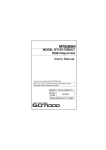
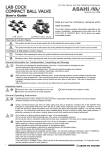
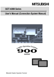
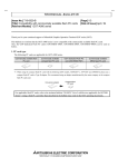
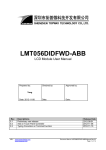
A9GT-80V4R1 Type Video/RGB Hybrid Interface Module User’s Manual (Hardware) Thank you for buying the MELSEC-GOT Series Prior to use, please read both this manual and detailed manual thoroughly and familiarize yourself with the product. MODEL A9GT-80V4R1-U-HW MODEL 1DM222 CODE IB(NA)-0800226-C (0508)MEE Mitsubishi Graphics Operation Terminal ! SAFETY PRECAUTIONS ! (Always read before starting use) When using Mitsubishi equipment, thoroughly read this manual and the associated manuals introduced in the manual. Also pay careful attention to safety and handle the module properly. These precautions apply only to the installation of Mitsubishi equipment and the wiring with the external device. Refer to the user’s manual of the CPU module to be used for a description of the PLC system safety precautions. These SAFETY PRECAUTIONS classify the safety precautions into two categories: "DANGER" and "CAUTION". DANGER Procedures which may lead to a dangerous condition and cause death or serious injury if not carried out properly. Procedures which may lead to a dangerous condition and CAUTION cause superficial to medium injury, or physical damage only, if not carried out properly. Depending on circumstances, procedures indicated by CAUTION may also be linked to serious results. In any case, it is important to follow the directions for usage. Store this manual in a safe place so that you can take it out and read it whenever necessary. Always forward it to the end user. A-1 [DESIGN PRECAUTIONS] DANGER ! Do not bundle control lines or communication wires together with main circuit or power lines, or lay them close to these lines. As a guide, separate the lines by a distance of at least 100 mm (3.94 inch) otherwise malfunctions may occur due to noise. [INSTALLATION PRECAUTIONS] DANGER ! Before mounting or dismounting this module to or from the GOT, always shut off GOT power externally in all phases. Not doing so can cause a module failure or malfunction. CAUTION ! Use this module in the environment given in the general specifications of the GOT User's Manual. Not doing so can cause an electric shock, fire, malfunction or product damage or deterioration. ! When installing this unit to the GOT, fit it to the connection interface of the GOT and tighten the mounting screws in the specified torque range. Undertightening can cause a drop, failure or malfunction. Overtightening can cause a drop, failure or malfunction due to GOT or screw damage. [WIRING PRECAUTIONS] DANGER ! Plug the cable into the connector of the connected module and tighten the mounting and terminal screws in the specified torque range. Undertightening can cause a short circuit or malfunction. Overtightening can cause a short circuit or malfunction due to the damage of the screws or module. [STARTUP AND MAINTENANCE PRECAUTIONS] DANGER ! Before starting cleaning, always shut off GOT power externally in all phases. Not doing so can cause a module failure or malfunction. A-2 [STARTUP AND MAINTENANCE PRECAUTIONS] CAUTION ! Do not disassemble or modify any module. This will cause failure, malfunction, injuries, or fire. ! Do not touch the conductive areas and electronic parts of this module directly. Doing so can cause a module malfunction or failure. ! Exercise care to avoid foreign matter such as chips and wire offcuts entering the module. Not doing so can cause a fire, failure or malfunction. ! Always secure the cables connected to the module, e.g. run them in conduits or clamp them. Not doing so can cause module or cable damage due to dangling, moved or accidentally pulled cables or can cause a malfunction due to a cable contact fault. ! Do not hold the cable part when unplugging any cable connected to the module. Doing so can cause module or cable damage or a malfunction due to a cable contact fault. [DISPOSAL PRECAUTIONS] DANGER ! Dispose of this product as industrial waste. A-3 Revisions *The manual number is given on the bottom left of the back cover. Print Date MAY, 2002 MAY, 2002 *Manual Number IB(NA)-0800226-A IB(NA)-0800226-B AUG., 2005 IB(NA)-0800226-C Revision First edition Partial correction Chapter3, Chapter4 Partial correction Chapter1 MODEL CODE change Changed from 13JT90 to 1DM222. This manual confers no industrial property rights or any rights of any other kind, nor does it confer any patent licenses. Mitsubishi Electric Corporation cannot be held responsible for any problems involving industrial property rights which may occur as a result of using the contents noted in this manual. 2002 MITSUBISHI ELECTRIC CORPORATION A-4 CONTENTS 1. Overview........................................................................................................ 1 2. Specifications................................................................................................. 3 2.1 A9GT-80V4R1 specifications ................................................................... 3 2.2 Cable specifications ................................................................................. 4 2.2.1 Specifications of the cables (coaxial cables) used when displaying video images ................................................... 4 2.2.2 Specifications of the cables (9-core combined cables) used when displaying RGB screens .................................................. 6 3. Name of the part’s and outline dimension drawing ........................................ 7 4. Installation procedure .................................................................................... 8 A-5 About the Manuals The following manuals are related to this product. Refer to the following list and request the required manuals. Detailed Manuals Manual name A985GOT/A975GOT/A970GOT/A960GOT User’s Manual (Available as an Option) Manual No. (Model code) SH-3311 (1DM098) Related Manuals For relevant manuals, refer to the PDF manual stored within the drawing software used. A-6 1. Overview This user’s manual describes the A9GT-80V4R1 Type Video/RGB Hybrid Interface Module (referred to as the A9GT-80V4R1 hereinafter). The A9GT80V4R1, when mounted together with the A985GOT-TBA-V or A985GOT-TBDV (collectively referred to as the A985GOT-V hereinafter), can display images taken by video cameras as well as on your personal computer on the A985GOT-V monitor. A985GOT-V Video camera A9GT-80V4R1 A 1254 B 348 ’ Ó̂ CAUTION ë “® ì Ì‚ °‹ ê Œ ‚ ‚è ‚ Ê ’ “d † ’ … ’ E ’ µ ‚ È ‚ ¢ ‚ Å ‚ -‚ ¾ ‚ ³‚ ¢ ‚ Do no t mount not desmount a module while the power is supp lied. Computer PLCs for line control *1: When connecting with a personal computer, your computer’s earth wire should be grounded. *2: Several types of video cameras, when used with A9GT-801V4R1, may cause a PLC or GOT to malfunction due to the noise that comes through the power cables for the cameras. Supply power to the cameras from different power supply for PLC or GOT. (Do not supply power to them from the same consent.) Be sure to attach the following line filter to each of the camera power line, if it is impossible to supply power from different power supply. Recommended line filter: ZHC2203-11 (TDK Corporation) or equivalent product. *3: The CRT of the personal computer and the A985 GOT-V monitor cannot display the same image simultaneously. *4: Both video images and PC screens cannot be displayed on the GOT at the same time. 1 The A9GT-80V4R1 can use the functions of both the conventional video input interface module (A9GT-80V4) and the RGB input interface module (A9GT80R1). The following shows the comparison between the conventional and new models: Item Video window RGB screen A9GT-80V4R1 A9GT-80V4 A9GT-80R1 • A9GT-80V4R1 cannot be mounted to the GOT other than A985GOT-V. • When using A985GOT-TBA-V, select the product with hardware version L (manufactured from January, 2002) or later. • For details of the system configuration, refer to the GOT-A900 Series User's Manual (Connection System Manual). • For details of the video input function and RGB input function, refer to the following manual. For GT Designer : GT Works Version /GT Designer Version Reference Manual For GT Designer2 : GT Designer2 Version Reference Manual • When the Video/RGB input interface unit is used, the following software package is required. Type A9GT-80V4R1 Compatible software package GT Works2 GT Works GT Designer2 GT Designer SW5D5C-GTWORKS-E SW1D5C-GTWK2-E version 26C or later version A or later SW5D5C-GOTR-PACKE SW1D5C-GTD2-E version 26C or later version A or later After opening the box, check that the following items are present. Description Quantity A9GT-80V4R1 1 2 2. Specification 2.1 A9GT-80V4R1 specifications Video input section Item Video input Color system Monochrome Number of video input channels Input signal Display size [dot’s] Specifications NTSC format, PAL format (interlaced format) EIA format, CCIR format (interlaced format) 4 channel IVp-p, 75 , composite signal 640x480 (possible to reduce to 320x240, 160x120) 720x480 (possible to reduce to 360x240, 180x120) Video external connection Coaxial cable method Applicable wire size 75 coaxial shield cable Analog RGB RGB input method (dot’s) (SVGA; 800x600, VGA; 640x480) Number of video input 1 channel channels Input image signal 1V-p, 75 RGB Synchronizing signal TTL, 1k input 800 600 (refresh rate 60, 72, 75 [Hz]) section Display size [dot’s] 640 480 (refresh rate 60, 72, 75, 85 [Hz]) *1 RGB external connection D-Sub15 pin method Applicable wire size 9-core combined cable (recommended) According to the specifications of the personal Maximum cable length [m](feet) computer/vision sensor/video camera to be used. *2 73(H) 105(W) 43(D) (Value for a single A9GTExternal dimensions 80V4R1 module, not including the protruded section) 5 V DC internal current consumption 0.5 (Value for a single A9GT-80V4R1 module) [A](5VDC) Weight [kg](Ib) 0.2 (0.44) (Value for a single A9GT-80V4R1 module) *1: If VGA (640 480 dots) is used, since the resolution differs from that of the A985GOT-V (800 600 dots), blank spaces will be displayed in black. *2: The length of the cable differs according to the specifications of the personal computer/vision sensor/video camera to be used. Be sure to use the cable whose length is as specified for the PC/vision sensor/video camera to be used. *3: Both video images and RGB screens cannot be displayed on the A985GOTV at the same time. 3 2.2 Cable specifications The cable specifications, connection drawings, and connectors used in the A9GT-80V4R1 are shown below: 2.2.1 Specifications of the cables (coaxial cables) used when displaying video images (1) Coaxial cable Use high frequency coaxial cable "3C-2V" "5C-2V" (conforms to JIS C 3501) for coaxial cable. The following shows the coaxial cable specifications. Item 3C-2V 5C-2V Internal condcuctive Insulating material material Construction Cable diameter Allowable bending radius Internal conductive material diameter Insulation material diameter External conductive material diameter Applicable connector plug Sheath External conductive material 5.4mm (0.21in) 7.4mm (0.29 in) 22mm (0.87 in) or more 30mm (41.18 in) or more 0.5mm (0.02 in) (Annealed copper wire) 0.8mm (0.03 in) (Annealed copper wire) 3.1mm (0.12 in) (Polyethylene) 4.9mm (0.19 in) (Polyethylene) 3.8mm (0.15 in) (Single annealed copper wire mesh) 5.6mm (0.22 in) (Single annealed copper wire mesh) Connector plug for 5C-2V (BNC-P-5-N1-CAU is recommended.) Connector plug for 3C-2V (BNCP-3-N1-CAU is recommended.) (2) Connector and connector cover • GOT connector Use BNC connector for GOT side connector. The following shows the connection method for BNC connector and coaxial cable. (a) Structure of BNC connector and the coaxial cable. Parts of the BNC connector Structure of the coaxial cable Nut Plug shell Washer Clamp Outer sheath Outer conductor Insulating material Internal conductive material Gasket Contact 4 (b) Connecting the BNC connector with the coaxial cable. 1) Remove the outer sheath of the end of the coaxial cable as shown 15mm below. (0.59inch) Remove the outer sheath. Clamp 2) Slip a nut, a washer, a gasket, and a clamp on the coaxial cables as shown below, and loosen the outer conductor. Nut Washer Gasket Internal conductive material 3) Cut the outer conductor, insulating material, and internal conductive material to specified dimensions shown below. Cut the outer conductor and extended it over the end of the clamp. Insulating material 3mm (0.12inch) 6mm (0.24inch) Clamp and outer conductor 4) Solder the contact to the tip of the internal conductive material. Soldering 5) Insert the contact assembly in the plug shell, and engage the plug shell with the nut. *1: Soldered part must not have excess solder mound. *2: The tail end of the contact must come into close contact with the cut end of the insulating material. The contact must not be cutting in the insulating material. *3: Apply solder quickly so that the insulating material may not be deformed by heat. • Connector at the video camera and vision sensor. Use the connector applicable to the video camera and vision sensor. (3) Precautions for cable preparation The length of the cable varies depending on the personal computer/vision sensor to be used. Create within the range of personal computer/version sensor specifications. 5 2.2.2 Specifications of the cables (9-core combined cables) used when displaying RGB screens (1) Cable specifications Item Specifications Applicable cable Equivalent to SP23-23352A UL20276-SB Applicable wire size 9-core combined cable (recommended) (2) Connection diagram 75 Coaxical GOT side R RGND G GGND B BGND DGND DGND HSYNC VSYNC NC NC NC NC NC 1 6 2 7 3 8 5 10 13 14 4 9 11 12 15 Personal computer side Twisted pair 1 6 2 7 3 8 5 10 13 14 4 9 11 12 15 R RGND G GGND B BGND GND GND HSYNC VSYNC GND NC GND SDA SCL (3) Connector • GOT connector Use the connector matching the following model for the GOT. 15-pin D-sub (male) inch screw type Manufactured by DDK 17HE-R13150-73MC2 • Connector at the personal computer/vision sensor Use the connector applicable to the personal computer/vision sensor. (4) Precaution for cable creating The length of the cable varies depending on the personal computer/vision sensor to be used. Create within the range of personal computer/vision sensor specifications 6 3. Name of the Part’s and Outline Dimension Drawing 105 (4.13) 1) 73 (2.70) A8GT-80V4R1 4) CAUTION 5) Do not mount not desmount a module while the power is supplied. VIDEO IN CH.1 CH.2 CH.3 CH.4 REAR SIDE RGB IN DISPLAY SIDE 2) 2) 2) 4) 43 (1.69) 2) No. 1) 2) 3) 4) 5) Name Connector for connection Connector for video input Connector for RGB input Option module mounting screw Rating plate 3) Unit: mm (inch) Description Connector for connection to the A985GOT-V Connector for connecting a coaxial cable Connector for connecting a 9-core combined cable Mounting screw to the A985GOT-V - 7 4. Installation Procedure (1) Insert the A9GT-80V4R1 connector into the option module interface at the back of A985GOT-V. A985GOT-V back A9GT-80V4R1 (2) Tighten the attachment screw to a point within the prescribed torque range of 39 to 59 N"cm. To remove the unit, reverse the installation procedure. 8 Warranty Mitsubishi will not be held liable for damage caused by factors found not to be the cause of Mitsubishi; machine damage or lost profits caused by faults in the Mitsubishi products; damage, secondary damage, accident compensation caused by special factors unpredictable by Mitsubishi; damages to products other than Mitsubishi products; and to other duties. For safe use " This product has been manufactured as a general-purpose part for general industries, and has not been designed or manufactured to be incorporated in a device or system used in purposes related to human life. " Before using the product for special purposes such as nuclear power, electric power, aerospace, medicine or passenger movement vehicles, consult with Mitsubishi. " This product has been manufactured under strict quality control. However, when installing the product where major accidents or losses could occur if the product fails, install appropriate backup or failsafe functions in the system. Country/Region Sales office/Tel U.S.A Mitsubishi Electric Automation Inc. 500 Corporate Woods Parkway Vernon Hills, IL 60061 Tel : +1-847-478-2100 Brazil MELCO-TEC Rep. Com.e Assessoria Tecnica Ltda. Rua Correia Dias, 184, Edificio Paraiso Trade Center-8 andar Paraiso, Sao Paulo, SP Brazil Tel : +55-11-5908-8331 Germany Mitsubishi Electric Europe B.V. German Branch Gothaer Strasse 8 D-40880 Ratingen, GERMANY Tel : +49-2102-486-0 U.K Mitsubishi Electric Europe B.V. UK Branch Travellers Lane, Hatfield, Herts., AL10 8XB,UK Tel : +44-1707-276100 Italy Mitsubishi Electric Europe B.V. Italian Branch Centro Dir. Colleoni, Pal. Perseo-Ingr.2 Via Paracelso 12, 20041 Agrate B., Milano, Italy Tel : +39-039-6053344 Spain Mitsubishi Electric Europe B.V. Spanish Branch Carretera de Rubi 76-80 08190 Sant Cugat del Valles, Barcelona, Spain Tel : +34-93-565-3131 France Mitsubishi Electric Europe B.V. French Branch 25 Boulevard des Bouvets, F-92741 Nanterre Cedex, France TEL: +33-1-5568-5568 South Africa Circuit Breaker Industries LTD. Tripswitch Drive, Elandsfontein Gauteng, South Africa Tel : +27-11-928-2000 Country/Region Sales office/Tel Hong Kong Ryoden Automation Ltd. 10th Floor, Manulife Tower, 169 Electric Road, North Point, HongKong Tel : +852-2887-8870 China Ryoden Automation Shanghai Ltd. 3F Block5 Building Automation Instrumentation Plaza 103 Cao Bao Rd. Shanghai 200233 China Tel : +86-21-6120-0808 Taiwan Setsuyo Enterprise Co., Ltd. 6F., No.105 Wu-Kung 3rd.RD, Wu-Ku Hsiang, Taipei Hsine, Taiwan Tel : +886-2-2299-2499 Korea HAN NEUNG TECHNO CO.,LTD. 1F Dong Seo Game Channel Bldg., 660-11, Deungchon-dong Kangsec-ku, Seoul, Korea Tel : +82-2-3660-9552 Singapore Mitsubishi Electric Asia Pte, Ltd. 307 Alexandra Road #05-01/02, Mitsubishi Electric Building Singapore 159943 Tel : +65-6473-2308 Thailand F. A. Tech Co.,Ltd. 898/28,29,30 S.V.City Building,Office Tower 2,Floor 17-18 Rama 3 Road, Bangkpongpang, Yannawa, Bangkok 10120 Tel : +66-2-682-6522 Indonesia P.T. Autoteknindo SUMBER MAKMUR Jl. Muara Karang Selatan Block a Utara No.1 Kav. No.11 Kawasan Industri/ Pergudangan Jakarta - Utara 14440 Tel : +62-21-663-0833 India Messung Systems Put,Ltd. Electronic Sadan NO:111 Unit No15, M.I.D.C BHOSARI,PUNE-411026, India Tel : +91-20-712-2807 Australia Mitsubishi Electric Australia Pty. Ltd. 348 Victoria Road, PostalBag, No 2, Rydalmere, N.S.W 2116, Australia Tel : +61-2-9684-7777 HEAD OFFICE : 1-8-12, OFFICE TOWER Z 14F HARUMI CHUO-KU 104-6212, JAPAN NAGOYA WORKS : 1-14, YADA-MINAMI 5-CHOME, HIGASHI-KU, NAGOYA, JAPAN When exported from Japan, this manual does not require application to the Ministry of Economy, Trade and Industry for service transaction permission. Specifications subject to change without notice. Printed in Japan on recycled paper.