1
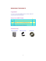
Fanless Mini PC
TV-850B
1,2 GHz Mini PC, with TV out, LPT, 2xCOM, 1z LAN
TC-850B
1,2 GHz Mini PC, 2xCOM, HDD sup., 1x LAN
RB-851B
1,2 GHz Mini PC, with CF, miniPCI, 1x LAN
RB-851BG 1,2 GHz Mini PC, with CF, miniPCI, HDD sup., 1x LAN
RB-852B
1,2 GHz Mini PC, with CF, 2xLAN, miniPCI
RB-853BS 1,2 GHz Mini PC, with CF, 2xLAN, HDD sup.
User’s manual
Table of Contents
SAFETY INFORMATION .............................................................................................. 2
REGULATORY ............................................................................................................. 3
UNPACKING YOUR MINI PC ........................................................................................ 4
PREFACE ..................................................................................................................... 5
Mini PC Overview ...................................................................................................... 6
ABOUT EMBEDDED CPU BOARD................................................................................. 7
PERIPHERALS.............................................................................................................. 8
CONNECTING THE POWER ADAPTOR .................................................................. 8
CONNECTING THE MONITOR ............................................................................... 8
CONNECTING THE USB ......................................................................................... 9
CONNECTING USB, SPEAKER/EARPHONE AND WEB............................................ 9
CONNECTING THE KEYBOARD AND MOUSE ........................................................ 9
BIOS ......................................................................................................................... 10
RECONFIGURING Mini PC ................................................................................... 10
TECHNICAL SPECIFICATION ...................................................................................... 11
TAKING CARE YOUR COMPUTER .............................................................................. 12
STORING ............................................................................................................. 12
USING CABLES FOR CONNECTION...................................................................... 12
CLEANING YOUR COMPUTER ............................................................................. 12
TROUBLESHOOTING ................................................................................................. 13
REAR PANEL ............................................................................................................. 14
REAR CONNECTORS OUTLINE FOR Mini PC TC-850B ......................................... 14
REAR CONNECTORS OUTLINE FOR Mini PC RB-851B ......................................... 14
REAR CONNECTORS OUTLINE FOR Mini PC RB-852B / RB-853BS ...................... 15
REAR CONNECTORS OUTLINE FOR Mini PC TV-850B ......................................... 15
PIN ASSIGNMENTS................................................................................................... 16
1
SAFETY INFORMATION
WARNING
Do not expose your computer to rain or moisture, in order to prevent
shock and fire hazard.
Never install your computer in wet locations.
Do not open the cabinet to avoid electrical shock. Refer to your nearest
dealer for qualified personnel servicing.
Never touch un-insulated terminals or wire unless your power adaptor
and display monitor are disconnected.
Locate your computer as close as possible to the socket outline for
easy access and to avoid force caused by entangling of your arms with
surrounding cables from the computer.
When using Mini PC, avoid using or installing the modem to the serial
port during a storm or a lightning.
Do not use the modem or a telephone to report a gas leak in the vicinity
of the leak.
USB connectors are not supplied with Limited Power Sources.
DO NOT ATTEMPT TO OPEN OR TO DISASSEMBLE THE CHASSIS
(ENCASING) OF THIS PRODUCT. PLEASE CONTACT YOUR
NEAREST DEALER FOR SERVICING FROM QUALIFIED TECHNICIAN.
2
REGULATORY
FCC CLASS A NOTE
This equipment has been tested and found to comply with the limits for a Class A digital device,
pursuant to Part 15 of the FCC Rules. These limits are designed to provide reasonable
protection against harmful interference when the equipment is operated in a commercial
environment. This equipment generates, uses and can radiate radio frequency energy and, if
not installed and used in accordance with the instruction manual, may cause harmful
interference in which case the user will be required to correct the interference at his own
expense. Testing was done with shielded cables. Therefore, in order to comply with the FCC
regulations, you must use shielded cables with your installation.
WARNING
This product Complies with EN55022 Class A. In a domestic environment this product may
cause radio interference in which case the user may be required to take adequate measures.
Changes or modifications to this unit not expressly approved by the party responsible for
compliance could void the user’s authority to operate the equipment.
This device complies with Part 15 of the FCC rules. Operation is subject to the following two
conditions: (1) this device may not cause harmful interference, and (2) this device must accept
any interference received, including interference that may cause undesired operation.
This digital apparatus does not exceed the Class A limits for radio noise emissions from digital
apparatus as set out in the interference - causing equipment standard entitled “Digital
Apparatus”, ICES-003 of the Department of Communications.
Cet appareil numérique respecte les limites de bruits radioélectriques applicables aux appareils
numériques de Classe (A) prescrites dans la norme sur le matériel brouilleur: “Appareils
Numériques”,NMB-003 édietée par le miniistre des Communications.
MANUFACTURER’S DECLARATION OF CONFORMITY
This equipment has been tested and found to comply with the requirements of European
Community Council Directives 89/336/EEC and 73/23/EEC relating to electromagnetic
compatibility and product safety respectively.
ATTENTION
This product has been designed and certified to comply with certain regulatory requirements
pertaining to Information Technology Equipment. This product has not been designed for use
as a medical device. Without limitation of the foregoing, this product is not intended and has
not been certified for use in a hospital or clinical environment to diagnose, treat, or monitor
patients under medical supervision, and is not intended and has not been certified to make
physical or electrical contact with patients, nor to transfer energy to or from patients and/or to
detect such energy transfer to or from patients.
3
UNPACKING YOUR MINI PC
Congratulation!
You have just acquire Mini PC RB/TC/TV series, the world’s smallest and
compact PC, please check the following items:
PACKING LIST FOR Mini PC SERIES
Item
Description
Q’ty
c
d
Mini PC
Max. 20-watts External Power Adaptor, Vin: 100~240VAC •
60/50Hz, 1.0A / Vout:: +5.0~5.25VDC @ 4A max. LPS
Drivers CD for Mini PC
User’s Manual
x1
x1
e
f
x1
x1
* Note: The accessories are subject to change without immediate notice.
CHECK BEFORE USE
c Mini PC EmbedBox
d AC Power Adaptor
4
e Drivers CD
PREFACE
Mini PC TV-850B/TC-850B/RB-851B/RB-851BG/RB-852B/RB-853BS
XtendLan introduces an industrial classic in the computing industry, by
featuring Mini PC RB/TC/TV series, a chef d’oeuvre compact PC that
connects people through networking via global internet across the continents
over the channels of sea bay. The conquest for browsing e- information
through wired LAN/WAN. This portable device is handy for travelers and
service technicians who worked in and out of the office. For office desk
workers, this showpiece occupies very little space on a corner of the table,
and it is so convenient that you may lock it in your drawer after office hours.
A jewel in the crown Mini PC RB/TC/TV series for thin client users, which is
handy-rugged-robust. Mini PC RB/TC/TV series serves as the Internet
Appliance that offers state-of-art design for applications surrounding
networking, computing, transaction and information transport.
XtendLan connotes the Mini PC RB/TC/TV series for small business
enterprises to serve these boxes to users for the connection to a server as
thin client. The Mini PC RB/TC/TV series achieves multi-servers requirement
to serve as firewall, mail-server, print server, and many other single task
application in the office. Furthermore, with Mini PC RB/TC/TV series,
business executive can work his way from the office to home, a student can
do his assignment from the dormitory and continue back at home. Mini PC
RB/TC/TV series allows you to use your computer with just one finger press
at the power button. It is built in an awesome mechanical dimension
of 170×124× 56mm, this is just a right device for space conscious
environment.
5
Mini PC Overview
Front Panel
Power LED
The power LED lights up, when system
is turn on.
HDD LED
The HDD LED flashes when the system
is working. Please do not turn off the
system when HDD start running
Power Switch
Depress switch to turn on & turn off the
systems.
USB port
For connection to devices with USB
interface (keyboard, mouse, HDD, CDROM, Memory Stick, etc.)
6
ABOUT EMBEDDED CPU BOARD
SYSTEM SPECIFICATION
CPU
Keyboard and Mouse
VIA Esther 1.2GHz
PS/2 Keyboard and Mouse
North/South Bridge
VIA CX700M
On-Board IDE
Support PIO, Bus Master, and Ultra
DMA/66 operation.
Can connect to 2 IDE devices.
Main Memory
512MB DDR2 (1GB RB-851BG)
BIOS
“Plug and Play” function, auto-search
new apparatuses inset.
Provide DMI for system management.
Advanced ACPI configuration and power
control interface. ( intelligence control
system.)
Peripheral
1. Printer port x1
(support SPP/EPP/ECP module)
2. USB2.0 ports x2
3. Serial port
4. Rear Audio (Mic-in, Line-out)
Dimension & Weight
170 x 123 x 56 mm / 970g
VGA
AGP Rev.2.0 Compliant
Resolution up to 1920x1440
Operating System
Suitable for –
Windows XP
Windows XP Embedded
Windows Embedded CE
WEPOS
LINUX
Audio
AC97 CODEO, Fully Compliant with
AC97v2.1
LAN
Realtek 8100B
10/100Base-Tx Ethernet Interface
7
PERIPHERALS
CONNECTING THE POWER ADAPTOR
Power Adaptor
To use your computer immediately, take
and use the supplied AC adapter as a
power source. See the left diagram for
visual connection.
Connect the DC power jack of the power
adaptor to the DC Input jack of Mini PC.
Turning ON Your Computer
Press the power button as indicated on
the figure on your left-side, the system
will start automatically.
CONNECTING THE MONITOR
VGA Connection
Depending on your choice of viewing,
select a conventional CRT or the LCD
VGA monitor.
8
CONNECTING THE USB
Mini PC provides USB port (one each in front & at the back of the cabinet).
Turning ON Your Computer
Front cabinet
Press the power button as indicated on
the figure on your left-side, the system
will start automatically.
CONNECTING USB, SPEAKER/EARPHONE AND WEB
USB Port
The second USB port is available for
connection to USB devices.
Connecting to WEB
There is an available RJ-45 LAN jack for
connection to the hub of your intranet;
and via your server for internet service
(see diagram for RJ-45 LAN jack).
Speaker/Earphone
Mini PC supports Input/Output device for
speaker,
earphone
and
MIC
(Microphone), etc…
CONNECTING THE KEYBOARD AND MOUSE
Describing Mouse actions
Description
Action
Point
-
Click
-
Double-click
Right-click
Scroll wheel
-
Slide and point your mouse to your
desired position.
Press the left button once.
Press the left button twice.
Press the right button once. When
selecting (most) programs, this action
displays a shortcut menu of the contextsensitive choices.
Move your finger along the wheel of your
mouse (just upright your middle finger)
and scroll vertically to move page upward
and downward.
Describing Keyboard
The keypad usually comes in standard
QWERTY;
except
that
different
language(s) keyboard comes with
additional special characters..
9
BIOS
RECONFIGURING Mini PC
1.
2.
3.
4.
Take note that AMI BIOS is used in the Mini PC. To reconfigure the computer,
depress or hit the <Del> key to enter your BIOS setup main menu.
Select from the menu, the desired setup for change.
Press <Esc> to go back to main menu.
Move your cursor to “Save Settings and Exit”, press “Y” to save the changes that
you just made. Mini PC will restart accordingly to your new setup.
10
TECHNICAL SPECIFICATION
Features
CPU
BIOS
System Chipset
I/O Chip
System Memory
Expansion
I/O
MIO
USB
Compact Flash Slot
Mini PCI Socket
Display
Chipset
Description
VIA Esther 1.2GHz
AMI BIOS
VIA CX700M
VT1211
Onboard 512MB DDR2 (1GB RB-851BG)
1x X-PCI connector
EIDE (Ultra DMA 133), 1x PS/2 K/B and Mouse
Print and RS-232 Port
USB 2.0 Ports (one in front)
Type I/II compact flash slot
124pin Mini PCI socket
Integrated VIA UniChrome 2D/3D Graphics with
MPEG4/WMV9 Accelerator
Up to 64 MB share system memory
Up to 1920 x 1440
Display Memory
Resolution CRT
Audio
AC97 2.2 (Codec)
VIA Vinyl VT1708
Audio Interface
Line out, , Mic in
Ethernet
Chipset
Realtek 8100BT
Remote Boot ROM
Built-in boot ROM function
Mechanical &Environment
Power Requirement+
5V~5.25V @ 4A
Operating Temperature0
0 ~ 60oC
Operating Humidity0%
- 90% relative humidity, non-condensing
Size (W x H x D)
170 x 123x 56mm
Weight780
780g / 940 g
11
TAKING CARE YOUR COMPUTER
This section gives you guidelines on using Mini PC computer – Safe using, Storing and
Handling.
STORING
Do not place your computer in a location that is subject to:
Heating sources, such as stove, oven, heater, radiator or air duct
Direct contact from sunlight
Rain or moisture area
Excessive dust accumulation area
High humidity place
Constant or occasional mechanical movement, vibration or shock
Strong magnets or magnetic fields or magnetically unshielded speakers
Ambient temperature of more than 95oF (35oC) or less than 32oF (0oC)
Do not place other electronic device or electrical equipment near your computer.
The electromagnetic field of the computer may cause interference subjecting to
malfunction.
Provide adequate air ventilation (circulation) to prevent internal buildup of heat.
Do not place your computer near the wall, behind the curtains or draperies, in
between two books that block its ventilation slots. Leave a space of at least
8 inches (20cm) behind the sides and back panel of the computer.
Change of environmental temperature: Problems may occur when there is a
sudden change of environmental temperature, or if the computer is brought
directly from a cold location to a warm one, moisture may condense inside your
computer. Turn off your computer, and contact your nearest dealer.
Checking the surrounding appliance(s) before using your computer. Since the
computer uses high-frequency radio signal and may interface with radio or TV
reception causing interference or poor signal display. When this happens,
relocate the computer by a suitable distance away from the set.
Do not drop the computer from the working table nor place heavy objects on top
of the computer.
USING CABLES FOR CONNECTION
To avoid problem, use only the specified interface cables in your accessory bag.
The supplier will not be responsible for the connection arising from the
other unspecified peripheral equipment.
Do not use cut or damaged cables for connection.
CLEANING YOUR COMPUTER
Clean the computer with a soft, dry cloth or a soft cloth lightly moistened with a
mild detergent solution.
Do not use any type of abrasive pad, scouring powder, or solvent such as
alcohol or benzine, as these may damage the finish of your computer.
When a solid object falls or a liquid spills onto the computer, turn off the
computer immediately and unplug the LAN and power cables. Contact a
qualified person or your dealer to check the computer before you use it again.
Always disconnect the power cord from the power source before cleaning the
computer.
12
TROUBLESHOOTING
This section describes the techniques of resolving some basic problems that you
encounter when using your computer. For more troubleshooting guidelines, please
contact your nearest dealer for technical support.
TROUBLESHOOTING YOUR EMBEDBOX
A. Computer does not start
Make sure the computer is properly secured and plugged into a power source
before it is turned on. Make sure the power indicator shows the power is on.
When the computer is plugged into a power strip or the UPS (Uninterruptible
Power Supply), make sure the power strip or UPS is turned on and working
normally.
Check if your VGA or LCD monitor is properly plugged into a power source and
turned on. Make sure the brightness and contrast controls are adjusted correctly.
See the manual that came with your display (monitor) for details.
Check if your power control button does not function, by removing the AC
adaptor. Wait for one minute, and then reattach all power connection before
pressing the power button.
Condensation may cause the computer to malfunction for a while. If this happens,
do not use the computer for at least one hour.
When you have checked all the above guidelines and the computer does not
work. Remove the power adaptor from the computer, unplug the power cord, and
plug it in again. Then turn on the power.
B. BIOS Error Message – BIOS error message appear when my computer starts
If the BIOS error message appears, press any key to resume or, hit <DEL>to enter
BIOS setup main menu, follow these steps:
1. Press <DEL>, and the BIOS Setup main menu appears, check if HDD is detected
at “Pri Master”. If it is not detected, use “Sel” keys <↑↓> to choose “AUTO”, then
go back to the main menu by pressing <ESC>. Move your cursor down with “Sel”
keys <↓>, and choose “Save Settings and Exit”, a message dialog appears as
seen below, hit <Enter>.
“Save current settings and exit (Y/N)? Y ”
2. Go to “Auto Configuration with Optimal Settings” using the “Sel” keys <↑↓>, then
press <Enter>. A message dialog appears as seen below, hit “ Y ” key and press
<Enter> to save and recover the factory setting.
“Load high default settings (Y/N)? N ”
C. “Operating System Not Found” – A message indicating that
“Operating system not found” appear when my computer starts (Windows
won’t start)
Enter your BIOS setup main menu by pressing <DEL> key, be sure that your C:
drive is enable.
If Windows still does not start, follow these steps to initialize the BIOS:
1. Turn off the computer.
2. Remove any peripheral devices connected to the computer.
3. Restart the computer..
4. Press <DEL> to enter BIOS Setup main menu window.
5. Follow the steps as written in item B. BIOS error message.
If you have just connect your computer to a USB Devices, remove these
peripherals.. And restart your computer to confirm that the Windows
operating system starts properly. If your computer continues to display the
message ”Operating system not found,” and Windows does not start, please
contact your nearest dealer for servicing.
13
REAR PANEL
REAR CONNECTORS OUTLINE FOR Mini PC TC-850B
DC Power Jack
Power Switch
PS/2 KB / MS
LAN
Printer Port
Mic In Line Out
Serial Port
REAR CONNECTORS OUTLINE FOR Mini PC RB-851B / RB-851BG
DC Power Jack
Power Switch
PS/2 KB / MS
LAN
Serial Port
Mic In Line Out
Compact Flash slot
14
REAR CONNECTORS OUTLINE FOR Mini PC RB-852B / RB-853BS
DC Power Jack
Power Switch
PS/2 KB / MS
Serial Port
LAN
Mic In Line Out
Compact Flash Slot
2nd LAN
REAR CONNECTORS OUTLINE FOR Mini PC TV-850B
DC Power Jack
Power Switch
PS/2 KB / MS
LAN S-Video out
Printer Port
Serial ports
15
Mic In Line Out
TV-out
PIN ASSIGNMENTS
Power Sw – Push Button Switch
Pin #
|
O
---
KBD(PS/2Keyboard & Mouse) – 6-pin Mini-Din
Connector
Pin #
Signal Name
1
KBCLK
2
PMCLK
3
GND
4
KBDAT
5
PMDAT
6
SB5V
7
GND
8
GND
9
GND
DC-IN (DC-IN 5V) – 3-pin MINI-DIN Lock Pin
Socket
Pin #
Signal Name
1
J23-pin 1 & 2
2
SB5V
NC
3
GND
4
Mouse (PS/2 Mouse) – 6-pin Mini-Din Connector
Pin #
Signal Name
1
PMCLK
2
NC
3
GND
4
PMDAT
5
NC
6
SB5V
7
GND
8
GND
9
GND
RJ-45 FOXCONN (LAN) – RJ45 Connector
Pin #
Signal Name
1
FTXD+
3
FRXIN+
5
NC
7
NC
VGA – 15-pin Dsub Connector
Pin #
1
2
3
4
5
Signal
Name
MR
MG
MB
NC
GND
Status
ON
OFF
---
USB1 (USB1x90o)– 4-pin USB Type 1 Connector
(Vertical Type)
Pin #
Signal Name
1
VCC
2
USB03
USB0+
4
GND
5
GGND
6
GGND
7
GGND
8
GGND
Pin #
2
4
6
8
Pin #
6
7
8
9
10
16
Signal Name
FTXDNC
FRXINNC
Signal
Name
GND
GND
GND
NC
GND
Pin #
11
12
13
14
15
Signal
Name
NC
VCC
HYSYNC
VSYNC
VCC
MIC_IN – 5-pin RCA Phone Jack
Pin #
1
2
3
4
5
COM - 9-pin Dsub Connector
Pin #
1
3
5
7
9
USB (USB2): For connection to external USB
device –4-pin USB Type 1 Connector (H)
Signal
Name
GND
MIC1
Open
Touch
Open
Touch
VREFOUT
Pin #
1
2
3
4
5
6
Signal
Name
VCC
USB2USB2+
GND
NC
NC
LEDS: POWER ON/OFF & HDD R/W
LED
State
Color
Blue
Power On
Red
HDD On
Red
HDD R/W
Flashes
Signal
Name
DCD1
TXD1
GND
RTS1
RI1
Pin #
2
4
6
8
--
17
Signal
Name
RXD1
DTR1
DSR1
CTS1
--