1
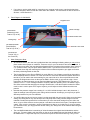
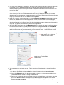
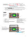
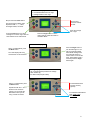
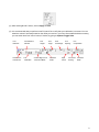
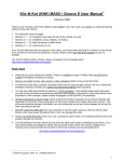
KNK MAXX User Guide for Previous KNK Owners1 By Sandy McCauley August 11, 2010 This document presents the major changes in operating a MAXX versus the original Klic-N-Kut and the differences in the software. Note that the full KNK MAXX User Manual you will receive not only includes these particular changes but has been enhanced and re-organized. For example, it now has nine chapters versus six and certain sections have been moved to the appropriate chapters where they belong. There are new sections, more screen shots, and re-written passages to provide more and, hopefully, clearer information. 1. Important Changes to Note: The software no longer comes with a dongle and you can only install and activate the software on TWO computers. Thus carefully select which two computers you wish to use and follow the instructions carefully in the user manual. In the event of a computer crash or the purchase of a new computer, please contact Accugraphic at 800-268-3672 for assistance with a new activation. If you kept your previous Klic-N-Kut, then you still have a copy of the previous software and a dongle. You can set up either software to cut to either KNK, but you’ll want to contact me first and I can help you with that. The tables which are provided with the Groove-E, 15” MAXX, and 24” MAXX are attached to the cutter with screws and do not require any support surface beneath, thus they can overhang a desk or table. Refer to the instructions in Section 1.7 of the User Manual on how to attach these tables. The new mat is thicker, printed with a grid, and the outside dimensions are 24” x 14”. Spray the top printed side with the Krylon adhesive or your preferred adhesive. Avoid direct contact between the pinch wheels and the mat as the rubber on the wheels will tend to pick up the adhesive and then later stick to the paper or cardstock you are cutting. Several ways to accomplish this are: Make sure the pinch wheels you are using are over the material you are cutting. o Place strips of scrap cardstock or paper along the area of the mat where the pinch wheels will be traveling. o The new mats have specific areas marked for the common paper sizes used. Consider masking off the rest of the mat, except for those areas, and spraying the adhesive only in those regions. o Apply silicon spray or silicon grease to the pinch wheels to prevent the adhesive from sticking to the rubber wheels. If using spray, do not spray the wheels directly; instead spray a clean rag or a paper towel and then apply the wet paper towel to the wheels, or use a cotton swab to apply the silicon to the wheels. If you inadvertently do get adhesive on the rubber wheels, they may be cleaned with isopropyl alcohol or Un-Du. Move the wheel away from a grit shaft, apply the cleaner to a clean rag or paper towel, and rub the entire wheel until free of adhesive. There are three pinch wheels on the MAXX models. Whenever you are cutting, you should be using at least two. If you are using only two, then slide either the right one or the left off to the side and do not drop the lever on that wheel. 1 o Take note of the white rectangular positioning labels on the cutter. (Refer to the parts diagram on the next page). These are directly above individual grit shafts and will assist you in positioning the pinch rollers before dropping the levers. As with your previous KNK, it’s important to have the rollers over the grit shafts, so always have the wheels under white rectangles! © 2008, 2009, 2010 Sandy McCauley., All Rights Reserved 1 If you plan to use the serial cable for connecting your computer to the cutter, note that the baud rate must be changed to 9600 on both the cutter and in the software. The instructions for that are shown in Sections 1.4 and Section 2.1. 2. Parts Diagram of KNK MAXX: Keypad Panel Pinch Wheel Positioning Label: Total of 4 (5 on 24”) Blade Carriage Blade Holder Seat Cutting Strip Grit Shaft (beneath Pinch Wheels): Total of 4 (5 on 24”) Bolt-On Front Table Pinch Wheel: Total of 3 (2 on the Groove-E) 3. Other Changes to Note: As mentioned earlier, the new mat is gridded and also has markings indicating where you may wish to place certain sizes of paper or cardstock. These are only for your convenience and are not required. If you do plan to use them, the mat should be aligned along the right side of the machine. Note: in the 8.5” x 11” portrait location, only two pinch wheels will be used. If you wish to have all three over an 8.5” x 11” material, then align the mat along the left side of the machine and position your paper to fit under the three positioning labels on that side. The Keypad Panel on the Groove-E/MAXX is much different. You will want to carefully go through the various displays shown in Section 1.4 of the user manual. I have also included this section later in this tutorial so you can read it now versus waiting for your manual to arrive. One major difference is that pressing the Origin button does not then put the KNK in Online mode. It only sets the origin. I have found this to be handy because you can then immediately press the TEST button to do your test cut (which is now a 1” x 1.25” rectangle instead of a square). But after pressing TEST, the machine is put into Online mode and that would be one change I would make. I wish the machine remained in Offline mode in case I need to press TEST again. Anyhow, you will adjust to these differences with some practice. Note that the pressure ranges from a setting of 1 to 160 in individual steps. Later in this document, I show the settings I was using during test cutting various materials. As always, you may find you prefer different pressures for your own materials. You will find that you have a lot more control over the speed with the new model. When set to the lowest setting, the cutting will be very slow and this can really help when cutting intricate designs or thicker materials. But also this speed will be in effect when you move the blade carriage from one side to the other, so go to Online mode to set the speed at a rate that’s convenient for this part. Then adjust before cutting. Also, once the cut begins, use the Pause button to abort a cut. At this time, if you try to restart your cut after Pause, you may get erratic random cutting. So, always turn off the machine after using the Pause button. The new MAXX bladeholder is something of a blend between the original black bladeholder and the silver one. To insert a blade, push the button on the top of the bladeholder and the blade will slide into the bladeholder. To adjust the exposure, unscrew the top and unscrew the brass ring. Then you can 2 screw the top to adjust the length. Secure the blade length by tightening the brass ring. Detailed steps are shown in a diagram later in this tutorial. This new bladeholder will use any of your existing red capped, blue capped, and sliver blades, engraving drop-in tool and punch tool. Further, because of the new bladeholder seat (grip) on the the new models, you can also use any of your current bladeholders, even your old Wishblade or Craft Robo ones! There is a new Sliver 2 (SL 260) blade for cutting thicker materials and I highly recommend it. Between this blade and the extra cutting force, I’ve had great success cutting thicker denser materials more easily. You can also continue using your original sliver blade, too. Use 15 and 20 for the Overcut and Trailing Blade settings. Adjust for other materials or images based on recommendations in the user manual. The KNK will come with a laser calibration sheet. This is necessary because there can be slight differences in the location of the laser relative to the position of the bladeholder seat from one machine to the next. The sheet contains a brief list of the steps required to calibrate; the user manual provides much more detail. If you wish to go ahead and review this procedure, then it is presented later in this document. If needed, I will be available to help you, by phone, perform this calibration. You will notice that when the Groove-E/MAXX is turned on, but not cutting, it will sometimes make a faint whistling sound. This is due to what is called “micro stepping” and is caused by idling between two veins on the encoder. I have no clue what this means! This is the explanation given to me by Accugraphic and they told me it’s nothing to worry about. 4. Software Changes Minor Changes: When you use any of the shape tools (except Oval), you’ll see that the cursor has a little symbol of that particular shape. I suppose this is to remind you that you are in that window? Not sure. Also, when you are moving a basic shape in the select mode, it will appear again. Also, when you move any object now, you will see a line also move on the Rulers indicating the current location of the center of the selected object. The settings for changing the End Point location has been moved from the Plotter Options tab to the Plotter tab. No biggie there. Alt-click the center bounding box of a selected image and it will place a duplicate image dead-on the original. The four main toolbars now have little dots on the left side or the top that you use for dragging to a new location (instead of two little gray lines). I suppose this makes them a bit easier to see. Major Changes: The first time you launch the new KNK Studio (after installation), you will be asked if you want to register the software. If you answer No, then you will have only 10 opportunities to cut. If you answer Yes, then you can enter an Activation Pin that will come with your software (probably a label on the box that holds the software, cables, bladeholder, etc). Then the program will connect with CADLink’s computer and update your installation. You can do this on two computers. After that, the software cannot be activated again for 6 months. In the event that something goes awry with your hard drive or you need to purchase a new computer, then contact Accugraphic at 800-268-3672. Now for the fun stuff! The new MAXX version of KNK Studio has an enhanced color vectorization feature (Super Size), allowing better auto-tracing of poor resolution images. You select your imported graphic and go to Image>Prepare to Vectorize Wizard. Refer to Chapter 6 of the new User Manual Because the Scan and Trace Wizard doesn’t work as well in color, I removed that tutorial from the User Manual. You can achieve the same thing in this new Wizard. 3 A lot more of the GSD files will now import. Previously, if the spline tool had been used more than once in tracing an image in RoboMaster, then only the first path would import. Now they all import. So, definitely test your gsd’s for direct import instead of using other methods, as it will be much faster and require less editing. A new icon, called Character Picker, appears in the Text mode Smart Bar and will open up the entire character set for the currently selected font. This is a very handy feature when you are using dingbat fonts. From the character set window, you can scroll through the choices to locate the particular image you wish to use and click on it to add it to the Sign Blank. Under the Text tools, on the Tools toolbar, is a new Text Search and Replace function that works just like the one in MS Word or other Office Applications. I’m not sure how useful this will be, although coincidentally, I had a customer recently need this feature after she had created about 10 different titles with the same words, but in different fonts. She then decided she wanted to change one of the words in every title. This feature would have been perfect for this application. One of the BEST new features is called Materials, which is not exactly the name I would have chosen, but nonetheless this will be very handy. Instead of having to change the Overcut and Trailing Blade values every time you change blades or every time you’re working with extremely large or extremely small images, you can now save those settings under names you choose. Additionally, you can then choose the “Material” setting from inside the Layout>Blank Size window. After entering Overcut and Trailing Blade values, click on Add new material and enter a name. Drop down window listing saved Overcut/Trailing Blade combinations. You can now pounce and cut in one step. This is done by modifying the color at the top of the Smart Bar: 1. In the main Sign Blank window, use Ctrl-A to select all images and go to Layout>Ungroup. 2. On the Job Palette, double click the color you wish to change to a color to pounce within this file. This color should then appear at the top on the Smart Bar. 3. Double click on this color’s box on the Smart Bar and a window will open. At the bottom, check the box next to Pounce and then enter values for the Dash length and the Spacing of the dashes. Recommended starting values are 0.07 and 0.15, as shown. If working in metric, then try 2mm and 4mm for the Dash and Space. 4 Check the Pounce box. Click on Add or Change to activate Pounce for this color and close the window. Enter a value for the length of the dash. Enter a value for the spacing of the dashed cuts. 4. Click on Add. A new color number is assigned to that color and your images of that color should change to dashes lines on the screen. If not, then select the images, note the new color number and click on it by locating it on the Shop Palette. 5. Proceed with the normal cutting procedure. This new color will be dash line cut while other colors will be solid cut. Note that you can assign other colors to be dashed cut, as needed. 2 5. Keypad Panel 1 7 3 Go through the various modes below to experiment with the settings and understand each mode. 8 9 4 5 10 6 11 1. 2. 3. 4. 5. 6. LCD Display Test: Draws a small rectangle when cutter is in Offline mode Online / Offline Toggle Menu Repeat: repeats last cut when cutter is in Offline mode Pause: Will pause cutter in the middle of a cut; press again to resume cutting 7. Offline Mode: moves carriage to the left; Online Mode: increases cutting force 8. Offline Mode: moves mat to the back; Online Mode: increases cutting speed 9. Offline Mode: moves carriage to the right; Online Mode: decreases cutting force 10. Sets the Origin 11. Offline Mode: moves mat forward; Online Mode: decreases cutting speed Online Mode Display v = cutting velocity, mm/sec f = cutting force (scaled from 0 to 160) Step 1: Turn on the KNK. A welcome message will flash for a few seconds when cutter is first turned on. Then the cutter will come to rest in the Online Mode. Experiment with “+” and “-“ buttons, as shown. Increase/Decrease Velocity (Speed) Increase/Decrease Cutting Force (Pressure) 5 Offline Mode Display x = forward/back distance from origin y = left/right distance from origin Step 2: Press the Online button. Move the mat forward or towards the back This will change to Offline mode. Experiment with “+”, “-“, TEST, and Origin buttons, as shown. Press the Test button for a small rectangle to cut at the origin. Note the cutter will then be in Online Mode. Move the carriage left or right Press the Origin button to set the origin. Note the cutter will remain in the Offline Mode. Laser Mode Display Press the Origin button to turn the laser light on. You will see a red light appear below blade carriage. Also, the cutter will change to Online mode. To turn off the laser, repeat Steps 2 and 3 and then press the Origin button again. Step 3: In Offline Mode, press the Menu button. The Laser display will show and the laser can be activated. Setting Display Us = Traverse speed (movement of carriage when head is up) Br = Baud rate (keep at 57600) Step 4: In Online Mode, press the Menu button. Experiment with the “+” and “-“ buttons for the Traverse Velocity. Do not modify the Baud Rate unless you are using a serial connection. Increases/Decreases Traverse Velocity (Speed) Increases/Decreases Baud Rate: USB: 57600 Serial: 9600 6 Set Per Display Xp = Calibration of X scale Yp = Calibration of Y scale Step 5: In Online Mode, press the Menu button twice. Do not change these values. Instead, it is recommended that calibration of the KNK be done from within the KNK Studio program. Refer to Section 2.4. Press again to turn off the Menu function. Pause Display v = cutting velocity, mm/sec f = cutting force (scaled from 0 to 160 As shown above, use the “+” and “-“ buttons to change the cutting velocity or cutting force and press Pause again to resume the cut. …OR… Turn off the cutter to abort the cut. Press the Pause button during the cut and the cutter will immediate stop cutting. At the end of a cut, the Repeat button can be pressed to activate the same cut again. 6. Blade Assembly The blade must be carefully inserted into the blade holder. Do this over a soft surface (e.g. over a hand towel). It’s important to protect the fragile blade! To install, follow the numbered steps as shown: 4. Turn counterclockwise to move towards the top. 2. Gently insert non-sharp end into holder. An internal magnet will pull the blade inwards. 6. Turn clockwise until locked in place. 1. Push in and hold so that a blade can be inserted. 3. Turn counter-clockwise to retract the blade. 5. Turn clockwise to set blade length to match the thickness of the material being cut. 7. Pressure Settings o For vinyl, set the pressure setting to around 50. If it is too low, the blade won’t even reach the cutting surface. Cheaper vinyl, such as cling vinyl, may require a slightly higher pressure. o For computer paper, vellum, and foil, set the pressure setting to around 40. Heavier vellum will need more pressure, however. 7 o For heavier paper, like the more expensive patterned papers used in scrapbooking, set the pressure setting to around 50 - 65. o For lighter cardstocks, try a pressure setting of around 70 - 85. o For heavier cardstocks like Bazzill and Club Scrap, try a pressure setting around 100 - 130. Some Bazzill weaves may require multi-pass to complete cut the cardstock. This is not a function of pressure; rather a function of the inconsistency in the cardstock itself. Note that humidity can cause cardstock to absorb moisture and become difficult to cut. o For very thin chipboard, try a pressure setting of around 125 - 150. As with the heavier cardstocks, humidity can play a factor and multi-cut may be necessary. o For thicker chipboard, the pressure setting will need to be anywhere from 150-160 and multiple passes may be necessary to completely cut through the material. For more information on cutting chipboard, vinyl, fabric, and felt, refer to Sections 9.1, 9.2 and 9.3. 8. Calibrating the Laser Light This calibration is necessary to make sure your print and cuts are accurate. It only needs to be done one time. It is recommended that you take note of the final calibration numbers in case you ever need to reinstall the software. (1) It is necessary that metric be used in the calibration process. To temporarily switch KNK Studio to metric, go to Options>Toggle Units. (2) A calibration sheet has been included in your box. If it is missing, you can download this file from: www.scrapbookdiecutter.com/downloads.htm (3) Turn on the cutter. Press the Online button to go into offline mode. Press the Menu button to display “LED Laser.” Press the Origin button to turn on the laser light, which will appear below the blade carriage. (4) Insert a blade into the bladeholder and make sure enough blade protrudes to puncture the calibration sheet. Insert the bladeholder into the bladeholder seat on the cutter. (5) Do not place the calibration sheet on the mat; you will not be cutting. Instead, raise the pinch wheel levers and insert the paper into the cutter, aligning it evenly along the right side of the machine. (6) Again, press the Online button to return to offline mode. Because the pinch wheels have not be lowered you can manually move the paper forward or backwards by hand. Use the left and right “+” and “-“ buttons to move the laser light until it is directly over the red circle on the calibration sheet. Again, make sure the calibration sheet is snug against the right side of the machine. Gently push the bladeholder down to puncture a hole in the calibration sheet. Then remove the sheet: Puncture is on X = 14 line and halfway between Y = -27 and Y = -28. Thus the calibration values are X:14 and Y: -27.5 (7) The location of the puncture indicates the (X,Y) values to be entered into the Origin Adjust setting in the software. Go to Cut>Plotting Defaults and click on Setup. Select the Plotter Options tab. Check the Edit box. For the example above a value of 14.0 is entered for X and a vaule of -27.5 is entered for Y. 8 (8) After entering X and Y values, click on Apply and OK. (9) It is recommended that you perform a test Print and Cut to verify that your calibration is accurate. You can tweak the values if necessary based on the offset you receive in your test. Once satisfied with the accuracy, you can switch back from mm to inches, if desired, by going to Options>Toggle Units. Font Detective Horizontal vs. Vertical Text Font Selection Window Text Justification Font Height Vertical Alignment in Text Frame Mode Font Angle Kern Percentage Character Picker Line Spacing Spell Check Line Compression On-Screen Kerning Character Width 9