1
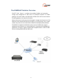
GSM2VoIP SIM Server DTT Up to 256 SIMs Version 1.1 User Manual Note: The most updated GSM2VoIP Gateway manual is located on our Web site, at: www.dtt.tw in the download section. Check this site for latest updates. Connecting to the Cellular with Remote SIM For additional assistance please contact us: Support Team Discovery Telecom Technologies Salt Lake City, USA Tel: +1801 7900348 Skype: discoverytelecom Email: [email protected] Web: www.dtt.tw Usage Warnings High voltage transients, surges, and other power irregularities can cause extensive damage. It is the user's responsibility to provide a power protection system. It is the user's responsibility to install, operate, and maintain the system in accordance with all applicable codes, regulations, and safety measures. Trademark and Patents All trademarks, patents and copyrights apply. General Manual Notes Without a notice and without ob ligation, the contents of this manual may be revised to incorporate changes and improvements. Every effort has been made to ensure that the information is complete and accurate at the time of publication. Nevertheless, Discovery Telecom cannot be held responsible for errors or commissions. The screen snapshots in this manual may have older version labels than your delivered package version. 2 Dear Customer, We thank you for purchasing our DTT GSM2VoIP SIM Server The information in this manual does not constitute a warranty of performance, although the information has b een compiled and checked for accuracy by Discovery Telecom Technologies Ltd. All our products are developed and produced by experienced engineers, who aspire to achieve customer satisfaction, utility value and reliability of products. Warranty Policy The product you have purchased is under warranty of 12 months from the date of purchase, by the original purchaser. In case of defects of materials or workmanship, Discovery Telecom will replace it free of charge. This warranty applies to hardware/software but does not include SIM Cards. This warranty will not be honored if the device has been mishandled in any way. We hope you enjoy our product and we will be happy to receive any comments you may have. This will enable us t o improve our products and the technical support that we give to every customer. 3 Table of Contents User Manual ................................ ................................ ................................ ............ 1 Getting Started ................................ ................................ ................................ ........ 5 Check Your Package Items ................................ ................................ ........................ 7 The GSM2VoIP Solution Overview ................................ ................................ .............. 8 Chapter 1: Installing SIM Cards and Connecting the Cables ................................ ......... 9 Chapter 1.1: Installing the SIM Cards ................................ ................................ ..... 9 Chapter 1.2: Connecting the Cables ................................ ................................ ......10 Chapter 2: Installing the Manager Application ................................ ......................... 11 Chapter 2.1: Install the GSM2VoIP Management Applic ation into an MS Windows PC ................................ ................................ ................................ 11 Chapter 3: Operating the SIM Server ................................ ................................ ....... 12 Chapter 3.1: Overview................................ ................................ ........................... 9 Chapter 3.2: Connecting to the PC Manegment ................................ ..................... 10 Chapter 3.3: Changing the IP Settings ................................ ................................ .... 9 Chapter 3.4: Replacing the SIMs ................................ ................................ ...........10 4 Getting Started Discovery Telecom team is glad you have chosen to use the Discovery’s GSM2VoIP Gateway for your needs. We will do our best, to make your installation efforts as well as day-to-day configuration and monitoring tasks , to be as pleasant as possible. We wish you a smooth operation , while greatly saving on your office mobile phone calls. This chapter is your “Map for installation, configuration and monitoring tasks” and includes a short explanation on each stage , as well as references for more elaborated explanations, drawings and examples in following chapters. The fo llowing is a list of tasks which are reco mmended to go through. It includes mandatory tasks as well as optional tasks that are not required for your current needs. It is advised , that you will use the following menu as your check-up To-Do-List. We advise you, to print this chapter and mark each stage when completed (e.g. V mark when done). Mandatory - Check package items delivered in your package Refer to the “Check your Package Items” chapter in order to see if all items, which should be in your package, are delivered . Mandatory – SIM cards installation and connections o Install SIM Cards o Install LAN cable o Install power coble Refer to “Chapter 1: SIM Cards Installation and Cables Connecting” for specific and detailed guidelines. Mandatory – Install the management application Install the MS-Windows Management Application on the PC/Laptop allocated for the system management. Use the provided CD. Refer to “Chapter 2: Installing the Manager Application ” for further information. Mandatory – General configurations 5 In order to operate the system, mandatory basic setup steps should be performed by using the LAN. 6 Check Your Package Items Please verify that your package contains the following components (some were ordered specifically) before installation: Main Hardware Device - The GSM2VoIP SIM Server 110/220V 50-60Hz Power Cable. LAN connection cable - for GSM2VoIP connection to the internet. TCP/IP Cross Cable (Red Cable) – for connecting the gateway directly to the PC Network Interface Card. RS-232 Serial PC Comport connec tion cable (RJ-45 to RS-232 COM) – for debugging and direct access to the config uration files. Will be referred as Com cable in this manual . Software Installation CD - Installation kit of the gateway Manager CD for MS-Windows Management Application, including the User Manual file and additional auxiliary utilities. 7 The GSM2VoIP Solution Overview The DTT™ SIM Server is a solution that enables flexible and convenient storage and management of SIM cards, for developed networks of mobile gateways. The Server offers virtual allocation of SIM cards via IP from one location to mobile gateways, no matter their location. SIM cards used are virtually stored and managed in a single central server unit. The SIM Server then allocates the SIM cards remot ely, via IP connection. Thus, a GSM modem may access to the remote SIM via GSM terminal adapter/SIM emulation. The SIM Server supports simultaneous access to up to 512 SIM cards. Typical applications use the device as a central SIM Server in distributed GS M/CDMA/3G applications. The device supports ISO/IEC 7816 compatible Smart -cards in ID-000 format including GSM RUIM and USIM cards. 8 Chapter 1: Installing SIM Cards and Connecting the Cables Chapter 1.1: The SIM Server layout The SIM Server consists of one master card, that controls the operation of the gateway, and SIM Server cards, that holds all the SIM cards. The master card has a connection to the LAN and the COM Port in the left of the SIM Server. The SIM Server cards are set from card 1 to c ard 8 from left to right, where card 1 is the closes to the SIM Server. Chapter 1.2: Installing the SIM Cards in the SIM Server cards Insert the SIM cards as follows: Open the two screws that secure the SIM Server card to the case. Pull the SIM Server card out. Each SIM Server card has 32 SIM sockets in it. The SIM sockets are marked from 1 to 32. To open the socket, slide the metal lock inward and push the socket up. Position the SIM in the socket, so the SIM metal contacts facing downward and the snubbed triangle outwards. Insert the SIMs in the socket. Push the socket down toward the card. Slide the metal lock of the socket outward until the SIM is locked. The SIMs now is in place. Slide the SIM Server card back in to is place. 9 Chapter 1.3: Connecting the Cables LAN cable - The LAN cable is used to connect the system to the internet network, connect the LAN line to the left RJ-45 marked LAN (the right RJ-45 that marked LAN are not in use) . Com Cable – Connect the Com Cable from the PC R S-232 comport to the left RJ-45 marked COM (the right RJ-45 that marked COM are not in use) . Power cable - Connect the power supply cable from your 110-240V 50-60Hz power outlet to the GSM2VoIP Gateway power connector. After connecting the power to the gateway, To power up the gateway turn the power switch, all the LEDs in the master will go on while the initialization process continue . At the end of this process the LED that marked 2 will start blinking and the LED that marked 1 will go off. 10 Chapter 2: Installing the Manager Application Before operation, configuration settings must be made in the GSM2VoIP. Configuration is done on an auxiliary computer by using the GSM2VoIP Management MS-Windows Application provided for MS -Windows operating system. Chapter 2.1: Install the GSM2VoIP Management Application into an MS-Windows PC 1. Insert the GSM2VoIP Management installation CD into the CD drive of the PC. 2. In Windows Explorer, navigate to the installation CD drive. 3. Double click 4. Click Next. 5. The Setup Type window will open. 6. Select Complete and click next. 7. Click Install. The GSM2VoIP Management application installs itself. Wait until a completion message will appear. to install the Management Application. 11 Chapter 3: Operating the SIM Server 3.1 Overview The work of the SIM Server is done automatically. Each time you insert a new SIM Server card, it scan the card. And he updates the data base of the SIMs. The data base of the SIMs and the settings for each SIM is kept in sim_server.xml file inside the SIM Server. When connecting with the PC management (port 2007), t he only setting that needs to be done with the PC software is the IP settings. That includes the IP Address of the unit, the Default Gateway address and the Subnet Mask. The rest of the settings are relevant only to the gateway. At the core of every GSM2VoIP unit there is a DSP processor. On the processor run a Linux operating system. On it run the v2g_2 program which operate the unit and a sim_server program which operate the internal SIM Server. The SIM Server is connected to the net with one IP Address in 3 different Ports, 2007 is the port for managing the unit, 2008 is the port for managing the SIMs, 2009 is the port of the Internal SIM Server. 3.2 Connecting with the PC management to the SIM Server 1. Launch the GSM2VoIP Management by pressing the GSM2VoIP logo on your PC desktop. 2. Press in the toolbar. The Selected Connection window will open. 3. Enter in the Host Address the IP Address of the SIM Server (The default IP address is 10.16.2.245). 4. Enter in the Port Number the port of the SIM Server (The default port is 2007). 12 Note: If you can't remember the IP Address see Appendix A: Com Port. 3.3 Changing the IP Address of the SIM Server 1. 2. 3. 4. 5. 6. Connect to the SIM Server with the current IP address port 2007. Open the VoIP window, the General tab. Enter in the IP Address box the new IP address for the gateway . Press Save. Disconnect from the gateway. Restart the gateway, wait 30 seconds for the of the initialization process. Note: This PC software is compatible for working with all types of the GSM2VoIP. When you are connected with the PC to the SIM Server, except the IP settings there is no other settings in the PC software that are relev ant to the SIM Server. 13 3.4: Replacing SIMs Replace the SIM cards as follows: Open the two screws that secure the SIM Server card to the case. Pull the SIM Server card out. Each SIM Server card has 32 SIM sockets in it. The SIM sockets are marked from 1 to 32. To open the socket, slide the metal lock inward and push the socket up. Position the SIM in the socket, so the SIM metal contacts facing downward and the snubbed triangle outwards. Insert the SIMs in the socket. Push the socket down toward the card. Slide the metal lock of the socket outward until the SIM is locked. The SIMs now is in place. Slide the SIM Server card back in to is place. The LEDs will blink slowly and then rapidly. The gateway will scan the information of the S IMs. When he will finish the LEDs will stop blinking. Note: After extracting a SIM Server card, you have to wait 30 seconds before sliding it back for the gateway to recognize that it was extracted. 14 Appendix A: Com Port The Com Port connection, give you direct access to the Linux based operating system files of the DSP. 1. Connect the Com Cable from the gateway to the PC RS232 Com Port. 2. Connect the Hyper Terminal press "Disconnect" than "Properties". 3. In the "Connect To" tab press "Configure", The "Po rt Setting" should be: 4. Press "OK" and move to the Settings tab. 5. Press ASCII Setup: 6. Sett this settings and press OK. 7. Press "Connect" in the Hyper Terminal. 8. When restarting the gateway you will see the initialization process. Wait until it finished. 9. Press the Enter button. On screen you will see #. 10. To see the IP settings write the command ifconfig and press Enter. 15 11. On screen you will: 12. The IP Address of the gateway is marked in a red circle. 16