1
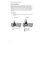
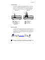
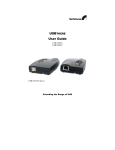
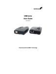
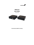
USBTHERE
User Guide
USB110EXT
USB120EXT
USB110 EXT shown
Extending the Range of USB
USBthere USB110EXT/USB120EXT
FCC Radio Frequency Interference Statement Warning
The USBthere has been tested and found compliant with the limits for a
Class B digital device, pursuant to Part 15 of the FCC Rules. These limits are
designed to provide reasonable protection against harmful interference when
installed and operated in a commercial environment. The USBthere
generates, uses, and can radiate radio frequency energy and, if not installed
and used in accordance with this user guide, may cause harmful interference
to radio communications. Operation of the USBthere in a residential area is
likely to cause harmful interference in which case the user will be required to
correct the interference at his own expense.
CE Statement
We, StarTech.com, declare under our sole responsibility
that the USBthere, to which this declaration relates, is in conformity with
European Standard EN 55022/A1 Class B, and EN 55024.
IC Statement
This Class B digital apparatus complies with Canadian ICES-003.
User Guide
Contents
Introduction................................................................................................ 1
Product Contents ........................................................................................ 1
About the USBthere ................................................................................... 2
Before You Begin ...................................................................................... 5
Installing the Local Unit ............................................................................ 5
Installing the Remote Unit ......................................................................... 5
Connecting the Local Unit to the Remote Unit.......................................... 5
Checking the Installation............................................................................ 6
Connecting a USB Device ......................................................................... 6
Troubleshooting ......................................................................................... 7
Specifications............................................................................................. 9
Technical Support .................................................................................... 10
Warranty Information .............................................................................. 10
i
USBthere USB110EXT/USB120EXT
Notes
ii
User Guide
Introduction
This manual is intended to assist IT professionals install the USBthere
USB110EXT/USB120EXT. The instructions in this guide assume a general
knowledge of computer installation procedures, familiarity with cabling
requirements, and some understanding of USB devices.
NOTE:
Notes give additional information that could make installation
easier.
Product Contents
When you open your product for the first time you should find the following
items:
•
•
•
•
USBthere USB110EXT/USB120EXT User Guide
Local Unit
Remote Unit
USB cable (2m long)
To complete the installation, you will also require the following items that
are not included with the product:
• USB compatible computer
• USB device
• Category 5 Unshielded Twisted Pair (UTP) cable with two RJ45
connectors (if using surface cabling),
OR,
Category 5 UTP cabling with two information outlets and two
Category 5 UTP patch cords with RJ45 connectors (if using
premise cabling)
NOTE:
The maximum length of the Category 5 UTP cable, including patch
cords, must not exceed 50m.
1
USBthere USB110EXT/USB120EXT
About the USBthere
The USBthere breaks the five-meter distance barrier for the connection of
USB peripheral devices and allows users to enjoy the benefits of USB
technology beyond the desktop. With the USBthere, USB devices can be
located up to 50 meters from the host computer. In addition, the USBthere
can supply power to remote low-power and some high-power USB devices.
The product is composed of two individual units, the Local Unit and the
Remote Unit.
The Local Unit
The Local Unit connects to the host computer using a conventional
USB cable.
Front View
Rear View
3
1
1 Host Port (USB Type B)
2
2
4
2 Host LED (green)
3 Link Port (RJ45)
4 Link LED (yellow)
User Guide
The Remote Unit
The Remote Unit connects to the USB device using a conventional
USB cable. The USBthere USB110EXT allows you to connect one
full-speed or low-speed USB device. The USBthere USB120EXT
allows you to connect two full-speed or low-speed USB devices.
Front View
Rear View
3
2
1
1 Device Port
(1 x USB Type A on
USB110EXT)
(2 x USB Type A on
USB120EXT)
4
2 Device LED (green)
3 Link Port (RJ45)
4 Link LED (yellow)
Network Cabling
The Local Unit and the Remote Unit are interconnected by up to 50
meters of Category 5 Unshielded Twisted Pair (UTP) cabling. The
UTP cabling must have a straight-through conductor configuration,
with no crossovers, and must be terminated with 8-conductor RJ45
connectors at both ends.
Remot e
Local
USB
cable
Comput er
Cat. 5 cable
USB
cable
USB
dev ice
NOTE: Category
5 UTP cabling is the standard data communications cable
installed in most commercial and some residential buildings.
3
USBthere USB110EXT/USB120EXT
USB Cables
USB cables have two distinct connectors. The Type A connector is used to
connect the cable from a USB device to the Type A port on a computer or
hub. The Type B connector is used to attach the USB cable to a USB device.
USB Type A
port
USB Type A
connector
USB Type B
port
USB Type B
connector
Power Handling
Some USB devices are powered directly from the USB and do not require
individual power supplies. These devices are called bus-powered devices.
The USBthere can provide power to these devices so they can be operated
remotely.
Bus-powered devices are further divided into low-power and high-power
categories. Low-power devices are allowed to draw up to 100 mA from the
USB. Typical examples include mice, joysticks, and keyboards without
hubs. High-power devices are allowed to draw up to 500 mA from the USB.
Typical examples include cameras and keyboards with hubs. To determine if
a device is high-power or low-power, consult the user documentation for the
device.
The USBthere can supply sufficient power to support all low-power devices
and most high-power devices. Devices that place a very heavy power drain
on USB (>300 mA) are not supported. Most USB devices operate well
within this power budget.
NOTE:
Devices with their own power source are usually considered to be
low-power devices from a USB perspective and are thereby
compatible with the USBthere.
Compatibility
The USBthere complies with USB 1.1 specifications governing the design of
full-speed and low-speed USB devices. However, StarTech.com does not guarantee that all USB 1.1 devices are co
the USBthere.
4
User Guide
Before You Begin
Before you can install the USBthere, you need to prepare your site.
1. Determine where the host computer is to be located and set up the
computer.
2. Determine where you want to locate the USB device.
3. If you are using surface cabling, ensure you have enough Category 5
UTP cabling to connect the two locations.
OR
If you are using premise cabling, ensure Category 5 UTP cabling is
installed between the two locations, with Category 5 information
outlets located near both the computer and the USB device.
Installing the Local Unit
1. Place the Local Unit near the host computer.
2. Plug the Type B connector on the USB cable (included) into the Host
port on the Local Unit.
3. Plug the Type A connector on the USB cable into the USB port on
the computer.
Installing the Remote Unit
1. Place the Remote Unit near the USB device.
Connecting the Local Unit to the Remote Unit
NOTE: To
ensure proper operation, we recommend that only Category 5, or
better, Unshielded Twisted Pair (UTP) cabling be used to connect
the Local Unit to the Remote Unit. The UTP cabling must have a
straight-through conductor configuration with no crossovers, and
must be terminated with 8-conductor RJ45 connectors at both ends.
With Surface Cabling
1. Plug one end of the Category 5 UTP cabling (not included) into the
Link port on the Local Unit.
2. Plug the other end of the Category 5 UTP cabling into the Link port
on the Remote Unit.
5
USBthere USB110EXT/USB120EXT
With Premise Cabling
1.
Plug one end of a Category 5 patch cord (not included) into the
Link port on the Local Unit.
2.
Plug the other end of the patch cord into the Category 5 information
outlet near the host computer.
3.
Plug one end of the second Category 5 patch cord (not included)
into the Link port on the Remote Unit.
4.
Plug the other end of the second patch cord into the Category 5
information outlet near the USB device.
NOTE:
The maximum length of the Category 5 UTP cable, including patch
cords, must not exceed 50 meters.
Checking the Installation
1.
Check that the Link LEDs on both the Local Unit and the Remote
Unit are on.
Connecting a USB Device
6
1.
Install any software required to operate the USB device. Refer to
the documentation for this device, as required.
2.
Connect the USB device to the Device port on the Remote Unit.
3.
Check that the Host LED on the Local Unit is on.
4.
Check that the Device LED on the Remote Unit is on.
User Guide
Troubleshooting
The following table provides troubleshooting help. The topics are arranged
in the order in which they should be executed in most situations. If you are
unable to resolve the problem after following these instructions, please
contact technical support for further assistance (see page 10).
Symptoms/Cause
All LEDs on Local Unit
are off.
Cause:
The Local Unit is not
receiving power from
the computer
Host LED on Local Unit
is on; Link LED on
Local Unit is off.
Cause:
There is no connection
between the Local Unit
and the Remote Unit.
Remedy
1. Ensure that the Local Unit is connected to a
USB port on the computer
2. Check that the computer is switched on and
that the OS is running (not in Sleep mode).
1. Ensure that a Category 5 UTP cable with
straight-through conductors is connected
between the Local Unit and the Remote Unit.
2. Ensure that Category 5 cables and connectors
are used throughout the entire link between
the Local Unit and the Remote Unit.
3. Check that Category 3 cable has not been
substituted.
4. Check that the cable length between the Local
Unit and the Remote Unit does not exceed 50
metres.
5. Connect a short Category 5 patch cord
between the Local Unit and the Remote Unit.
Recheck the operation of the system.
7
USBthere USB110EXT/USB120EXT
Symptoms/Cause
Remedy
Link LED on Local Unit
is on;
Host LED on Local Unit
is on.
Link LED on Remote
Unit is on;
Device LED on Remote
Unit is off.
Cause:
a) The USB device is
not connected to
the Remote Unit.
b) The USB device is
malfunctioning.
c) The computer does
not recognise the
USB device.
d) The computer does
not support USB
hubs.
e) The extender is
malfunctioning.
1. Check that the USB device is securely
connected to the USB port on the Remote
Unit.
2. Disconnect the Local Unit from the computer.
3. Connect the USB device directly to the USB
port on the computer.
4. If the device does not operate properly,
consult the user documentation for the device.
5. If the device operates properly when directly
connected to the computer, connect another
full speed device (of a different type) to the
Remote Unit. Connect the Local Unit to the
computer.
6. If the second device does not operate, the
extender may be malfunctioning. Contact
technical support for assistance.
7. If the second device does operate properly,
the first device may not be compatible with the
extender. Contact technical support for
assistance.
All LEDs on both Local
Unit and Remote Unit
are on but the device
does not operate
correctly
Cause:
a) The USB device is
malfunctioning.
b) The computer does
not recognise the
USB device.
c) The extender is
malfunctioning.
1. Disconnect the Local Unit from the computer.
2. Connect the USB device directly to the USB
port on the computer.
3. If the device does not operate properly,
consult the user documentation for the device.
4. If the device operates properly when directly
connected to the computer, connect another
full speed device (of a different type) to the
Remote Unit. Connect the Local Unit to the
computer.
5. If the second device does not operate, the
extender may be malfunctioning. Contact
technical support for assistance.
6. If the second device does operate properly,
the first device may not be compatible with the
extender. Contact technical support for
assistance.
8
User Guide
Specifications
Range (over Category 5
UTP cable)
50 meters (165 ft)
USB device support
USBthere USB110EXT: 1 x full-speed (12
Mb/s) ) or low-speed (1.5 Mb/s) device.
USBthere USB120EXT: 2 x full-speed (12
Mb/s) or low-speed (1.5 Mb/s) devices.
USB hub support
Up to 3 hubs connected in series.
Each hub reduces the maximum range by 10
meters.
Maximum power
available to USB at
Remote Unit
300 mA when the Local Unit is supplied with
500 mA;
600 mA when the Local Unit is supplied with
1000 mA
USB cable
2 meters (6.6 ft)
Local Unit connector
(upstream)
1 x USB Type B
Local Unit connector
(downstream)
1 x RJ-45
Remote Unit connector
(upstream)
1 x RJ-45
Remote Unit connector
(downstream)
USBthere USB110EXT: 1 x USB Type A
USBthere USB120EXT: 2 x USB Type A
Local Unit dimensions
100 mm x 70 mm x 30 mm (4.0” x 2.8” x 1.2”)
Local Unit weight
0.1 kg (0.2 lb)
Remote Unit dimensions
100 mm x 70 mm x 30 mm (4.0” x 2.8” x 1.2”)
Remote Unit weight
0.1 kg (0.2 lb)
Total system shipping
weight
0.4 kg (0.8 lb)
Temperature range
4°C to 40°C
Regulatory testing
FCC, CE Class B
9
USBthere USB110EXT/USB120EXT
Technical Support
The following technical resources are available for this StarTech.com product:
On-line help:
We are constantly adding new information to the Tech Support section of our
web site. To access this page, click the Tech Support link on our homepage,
www.startech.com. In the tech support section there are a number of options
that can provide assistance with this product.
Knowledge Base - This tool allows you to search for answers to common
issues using key words that describe the product and your issue.
FAQ - This tool provides quick answers to the top questions asked by our
customers.
Downloads - This selection takes you to our driver download page where
you can find the latest drivers for this product.
Call StarTech.com tech support for help:
USA/Canada: 1-519-455-4931
UK/Ireland/Europe: 00-800-7827-8324
Support hours: Monday to Friday 9:00AM to 5:00PM EST (except holidays)
Warranty Information
This product is backed by a one-year warranty. In addition,
StarTech.com warrants its products against defects in materials and
workmanship for the periods noted below, following the initial date of
purchase. During this period, the products may be returned for repair,
or replacement with equivalent products at our discretion. The
warranty covers parts and labor costs only. StarTech.com does not
warrant its products from defects or damages arising from misuse,
abuse, alteration, or normal wear and tear.
Limitation of Liability
• In no event shall the liability to StarTech.com Ltd. (or its officers,
directors, employees or agents) for any damages (whether direct or
indirect, special, punitive incidental, consequential, or otherwise),
loss of profits, loss of business, or any pecuniary loss, arising out of
related to the use of the product exceed the actual price paid for the
product.
10
User Guide
Notes
11
-