1
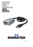
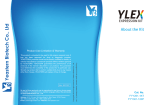
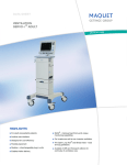
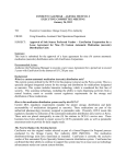
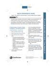
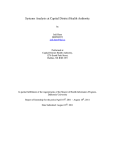
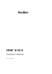
VELA ventilator
user guide
®
Critical care ventilation
Table of contents
VELA ventilator model matrix.......................1-2
Panels..........................................................3-8
Circuit assembly.........................................9-12
Primary controls.......................................13-16
Extended Functions..................................17-19
Operational verification testing................20-25
FiO2 Monitor Calibration..........................26-27
Ventilation.................................................... 28
Breath types.........................................29-35
Ventilation modes................................36-42
Apnea Backup ventilation.....................43-44
Noninvasive ventilation.........................45-46
Interfaces for NPPV..................................47-48
Advanced settings....................................49-55
Digital displays.........................................56-60
Graphics..................................................61-64
Loops screen............................................65-69
Trends screen...........................................70-71
End-tidal capnography (EtCO2 ).................72-78
Notes.......................................................79-81
The VELA® ventilator user guide is not intended as a replacement for the operator’s manual. You must
become completely familiar with the VELA ventilator operator’s manual before using the VELA ventilator.
i
VELA ventilator model matrix
Option
VELA
VELA +
VELA Comprehensive
% O2
X
X
X
100% O 2
X
X
X
FiO 2 Monitor
X
X
X
Nebulizer
X
X
X
Inspiratory Hold
X
X
X
Expiratory Hold
X
X
X
Assist/Control
X
X
X
SIMV
X
X
X
CPAP
X
X
X
Pressure Control
X
X
X
Pressure Support
X
X
X
Basic Waveform Graphics
X
X
X
PRVC/Vsync
X
X
NPPV
X
X
Leak Compensation
X
X
Loops
X
1
Option
VELA
VELA +
Trends
X
MIP/NIF
EtCO 2
VELA Comprehensive
X
Option
Option
Option*
Square Waveform
X
APRV/BiPhasic
X
Assured Volume
X
*Software is activated; hardware to be purchased.
2
Panels
A
Front panel
B
C
D
J
A.Effort indicator
PRESSURE A/C
B. Mode indicator
C. Screen indicator
40
380
0
mL
Vti
mL
Vte
I
D. Alarm status indicator
28
cmH2O
Ppeak
ALARM
SILENCE
2
4
6
8
10
ALARM
RESET
2
4
6
8
10
12
2
4
6
8
10
12
12
FREEZE
INSP
HOLD
MANUAL
BREATH
EXP
HOLD
-20
80
V (lpm)
40
0
-40
-80
21
500
750
0
-250
%
FiO2
MAIN
Paw (cmH2O)
20
5
cmH2O
PEEP
E. Power indicator
F. Data dial
391
250
Vt (mL)
NEBULIZER
100%
O2
PANEL
LOCK
H
G
20
22
1.0
5
5
21
BPM
Rate
cmH2O
Insp Press
Sec
Insp Time
cmH2O
PEEP
LPM
Flow trig
%
%O2
Man Brth Silence
Vol Min
Effort
G.Message window
ADV
SETTINGS
LIMITS
SETUP
ACCEPT
E
PRINT
DC
AC
H.Primary controls
DC
STATUS
CANCEL
F
FROM
PATIENT
TO
PATIENT
I. Monitored parameters
PRESSURE
RELIEF
J. Membrane buttons
3
Rear panel
A.Power switch
B. Fan and fan filter
C. High-pressure oxygen fitting
K
A
H
B
D. Low-pressure oxygen fitting
L
E. Nurse call system connection
M
E
F. Ground terminal
G.Future options
H.Alarm speaker
I. Power cord connector
J.Fuses
K. Parallel printer port
F
I
J
N
G
L. Video output port
M.MIB port
N.CO2 power box connector
4
C
D
Membrane buttons and LEDs
The VELA ventilator membrane panel differs between the International model
and the U.S. model.
O2
ALARM
SILENCE
ALARM
RESET
FREEZE
INSP
HOLD
MANUAL
BREATH
EXP
HOLD
NEBULIZER
100%
O2
PANEL
LOCK
ACCEPT
DC
AC
VELA ventilator membrane panel (International)
DC
STATUS
CANCEL
VELA ventilator membrane panel (United States)
5
Membrane button functions
Alarm Silence: Pressing this button disables the audible portion of an alarm for 60 seconds
(± 1 second) or until the ALARM SILENCE button is pressed again. This button is not functional
for a VENT INOP alarm.
Alarm Reset: Cancels the visual indicator for alarms that are no longer active.
Freeze: The FREEZE button freezes the current screen and suspends real-time update of data
until pressed again. When the screen is frozen, you can scroll through displayed waveforms,
trends or loops using the Data Dial to move the cursor on screen.
Inspiratory Hold: When the INSP HOLD button is pressed and held, once the preset volume
of a volume breath has been delivered, the patient is not allowed to exhale for a maximum of
6 seconds.
Expiratory Hold: When the EXP HOLD button is pressed and held, at the start of the next
breath interval, the ventilator does not allow the patient to inspire or exhale for a maximum
of 6 seconds.
Manual Breath: Pressing this button during the expiration phase of a breath delivers a single
mandatory breath at current ventilator settings. No breath is delivered if the button is pressed
during inspiration.
6
Membrane button functions (continued)
Synchronized Nebulizer: When an in-line nebulizer is attached and the NEBULIZER button is
pressed, the ventilator supplies nebulized gas to the patient at 6 L/min. When nebulization is
active, the nebulizer flow is synchronized with the inspiratory phase of each breath and can be
adjusted in increments of 1 minute for a maximum of 60 minutes. You may end the nebulization
period early by pushing the NEBULIZER button again.
Caution: Using the nebulizer may impact patient volumes. During volume control breaths,
approximately 50 mL is added to the Tidal Volume for every 0.5 seconds of inspiratory time.
If this added volume is undesirable for your patient, adjust the set Tidal Volume appropriately.
This added volume also slightly increases the Peak Pressure. Properly set High-Pressure alarms
help protect the patient from injury. Backpressure from a nebulizer can reduce nebulizer flow.
This backpressure varies depending on the manufacturer and/or brand of nebulizer used. The
user should be aware of this and take steps to account for the effect of backpressure. Neither
volume nor peak pressure is affected for Pressure Control or Pressure Support breaths.
Caution: Use of an external flow meter to power the nebulizer is not recommended.
7
Membrane button functions (continued)
O2
100% O2: When this button is pressed, the ventilator increases the oxygen concentration
delivered to the patient to 100% for 3 minutes. If the 100%O 2 button is pressed again
within the three-minute period, the maneuver is cancelled and the ventilator returns to
the prior settings for FiO 2.
Panel Lock: The PANEL LOCK button disables all front panel controls except MANUAL BREATH,
100 %O 2, ALARM RESET, ALARM SILENCE, and the PANEL LOCK button.
Accept: Accepts data entered into a field on the touch-screen.
Cancel: Cancels data entered into a field on the touch-screen. The ventilator continues to
ventilate at current settings.
8
Circuit assembly
1.Carefully seat the rim of the diaphragm on the exhalation valve, and gently press around the rim to ensure it is seated evenly as shown. Use diaphragm #10384 on models 15997, 16257, 16330 and 16186. Use diaphragm #16240 on models 16530, 16531, 16532
and 16600.
2.Line up the fins of the exhalation valve
body with the openings in the exhalation
valve housing.
9
3.Rotate clockwise until it clicks into place.
4.Attach the flow sensor with the
flow tubes in an upright position.
10
5.To connect the smart connector for the variable orifice flow sensor, pull back the locking sleeve. Push the locking sleeve into the receptacle, and slide it forward to secure. To remove, repeat these steps in reverse order.
11
Complete patient circuit assembly.
A.Nebulizer output
B. Expiratory flow sensor
C. Expiratory limb of patient circuit
D. Inspiratory limb of patient circuit
A
B
C
12
D
Primary controls
Activating a primary control
To activate a primary breath control, touch the touch-screen directly over the control.
The control highlights (changes color), indicating it is active. To modify the settings for
the highlighted control, turn the data dial below the touch-screen. Turning in a clockwise
direction increases the selected value; turning counterclockwise decreases it.
Primary breath controls
The primary breath controls are operator set controls, which directly affect the way a breath
is delivered to your patient. They are displayed along the bottom of the touch-screen. Only
the controls that are active in the currently selected mode of ventilation are displayed.
Displayed control
Description
Range
bpm
Rate
Breath rate in breaths per minute
2 to 80 bpm
mL
Vt
Tidal volume in milliliters
50 to 2,000 mL
cmH 2 O
Insp Pres
Inspiratory pressure in centimeters of water pressure
1 to 100 cmH2O
13
Primary breath controls (continued)
Displayed control
Description
Range
L/min
Peak Flow
Peak inspiratory flow in liters per minute
10 to 140 L/min
sec
Insp Time
Inspiratory time in seconds
0.30 to 10 sec
sec
Insp Pause
Sets an inspiratory pause, which is in effect for each volume
breath delivered
Off, 0.1 to 2.0 sec
cmH 2 O
PSV
Pressure Support in centimeters of water pressure
Off, 1 to 60 cmH2O
cmH 2 O
PEEP
Positive end-expiratory pressure in centimeters of
water pressure
0 to 35 cmH2O
L/min
Flow Trig
Sets inspiratory flow-trigger point in liters per minute
1 to 10 L/min
%
%O 2
Controls the percentage of oxygen in the delivered gas
21% to 100%
14
Primary breath controls (continued)
Controls associated with breath type and mode
Breath type
VOL
VOL
PRES
PRES
PRVC
PRVC
CPAP/
APRV/
NPPV
NPPV/
NPPV/
and mode
A/C
SIMV
A/C
SIMV
A/C
SIMV
PSV
BIPHASIC
A/C
SIMV
CPAP/PS
RATE
bpm
X
X
X
X
X
X
X
X
VOLUME
mL
X
X
X
X
X
X
X
X
INSP PRES
cmH2O
X
X
NPPV INSP PRES
cmH2O
PEAK FLOW
L/min
X
X
INSP TIME
sec
INSP PAUSE
sec
PSV
cmH2O
X
X
(not in
VSYNC)
X
X
X
X
(not in
VSYNC)
X
X
X
NPPV PSV
cmH2O
X
X
X
15
X
Primary breath controls (continued)
Controls associated with breath type and mode (continued)
Breath type
VOL
VOL
PRES
PRES
PRVC
PRVC
CPAP/
APRV/
NPPV
NPPV/
NPPV/
and mode
A/C
SIMV
A/C
SIMV
A/C
SIMV
PSV
BIPHASIC
A/C
SIMV
CPAP/PS
PEEP
cmH2O
X
X
X
X
X
X
X
X
X
X
X
FLOW TRIG
L/min
X
X
X
X
X
X
X
X
X
X
X
% OXYGEN
%O 2
X
X
X
X
X
X
X
X
X
X
X
PRES HIGH
cmH2O
X
TIME HIGH
sec
X
TIME LOW
sec
X
PRES LOW
cmH2O
X
Apnea (pressure
and volume settings)
X
16
X
X
Extended Functions
The Extended Functions screen in the Patient Screen Select dialog allows access to stored data
and customization of the front panel. To access Extended Functions, touch the Screen Indicator
in the top-center section of the touch-screen.
The Screen Select menu appears. Press Extended Functions.
The Extended Functions menu appears.
Events
Vent
Setup
Version
Info
Date
Time
CO2
Setup
Exit
17
Extended Functions (continued)
The Extended Functions menu is available from several different screens within the VELA
ventilator software screens. Some of the functions accessible from this screen are for use
by a trained technician when servicing the VELA ventilator.*
Events
Stores data events for service evaluation and troubleshooting*
Transducer test
Allows service testing of transducer function*
Version info
Displays the software version information and the turbine and
ventilator serial number
Date/time
Displays total hours of ventilator and turbine operation and the
date/time configuration
Vent setup
Allows setting of these functions:
Enable or disable an Off setting for the Low Minute
Volume alarm
Low Min Vol
Locks
Enable or disable the front panel lock switch
FiO 2 monitor
Turns the FiO 2 monitor on or off. Disabling results in the inability
to perform FiO 2 calibration and the inability to monitor the FiO 2
Altitude units of measure
Toggles between feet and meters for the altitude setting
Altitude setting
Allows setting of altitude for accurate volume measurement
Language buttons
Select the desired language for the front panel
* Denotes function for use by trained service technician.
18
Extended Functions (continued)
Vent setup (continued)
Allows setting of these functions (continued):
Allows setting of communications choice via MIB output
(VOXP, GSP)
Ext. Communications
Baud
Allows setting of Baud rate
Format
Allows user to change communcation format
End of Msg.
Allows user to change end of message
Neb Time
Allows setting of time (1 to 60 minutes) that nebulizer is active
Alarm Loudness
Allows setting of alarm loudness
Dim screen
Allows setting the screen to Dim or Bright
Video Normal/Inverse
Reverses the color configuration of the graphic interface
CO 2 Setup
Allows access to EtCO 2 setup to enable EtCO 2 monitoring
19
Operational verification testing
The user should carry out the following checks to ensure optimum performance. Verification
testing should always be performed off patient.
Note: All personnel performing preventive maintenance and product repair must be trained
and certified by CareFusion. If any portion of the following performance check fails, and you
are unable to correct the problem, contact your CareFusion certified service technician.
User verification tests
1. After disconnecting the patient, turn the ventilator off.
2. Press and hold the Accept button.
3. While holding the Accept button, turn the ventilator on. Continue to hold the button until
the ventilator completes the Power On Self Tests (POST).
4. Release the Accept button when the UVT Remove Patient message appears in the screen.
The Audible Alarm sounds. Press Alarm Silence button to clear.
20
User Verification tests (continued)
5. Press the Patient Removed touch-screen icon. The UVT test selection screen displays.
UVT STARTUP
ATTENTION: REMOVE PATIENT BEFORE PROCEEDING
PATIENT
REMOVED
6. Press the appropriate touch-screen icon to begin each test.
VOLUME A/C
40
ml
Vte
0
EPM
Rate
MAIN
Paw(cmH20)
20
UVT TEST SELECT
-20
80
V((
40
I:E
cmH2O
PEEP
SWITCH
TEST
ALARM
TEST
LEAK TEST
EXTENDED
FUNCTIONS
SERVICE
SETUP
0
-40
-80
cmH2O
Ppeak
LAMP
TEST
1500
10
12
10
12
10
12
EXIT
XPpp
1000
500
0
-500
2
4
6
8
Man Brth Silence
Effort
21
Vol Min
ADV
SETTINGS
LIMITS
SETUP
Lamp test
Run this test to make sure the front lamps are functioning properly.
1. Press the Lamp Test touch-screen icon to start the test. The ventilator illuminates
all front panel LEDs except the Power LED and the DC LED.
2. Press the Lamp Test touch-screen icon again to turn the LEDs off and exit the test.
You cannot start another test until you exit this test.
Switch test
Run this test to check the front panel membrane switches to make sure they are
working properly.
1. Press the Switch Test icon.
2. Press each membrane switch control in turn. Watch for the name of the control to
appear in the message bar at the bottom left of the touch-screen (see next page):
22
Switch test (continued)
Key Test: SILENCE
Key Test: RESET
Key Test: FREEZE
Key Test: INSP HOLD
Key Test: MAN BREATH
Key Test: EXP HOLD
Key Test: NEBULIZER
Key Test: 100% O2
Key Test: LOCK
Key Test: ACCEPT
Key Test: CANCEL
Message bar
3. Press the Switch Test icon again to exit the test. You cannot start another test until you exit
this test.
23
Alarm test
Run this test to check the audible alarm.
1. Press the Alarm Test touch-screen icon to start the test. The audible alarm sounds.
2. Press the Alarm Test touch-screen icon again to silence the audible alarm and exit the test.
You cannot start another test until you exit this test.
Leak test
Note: This test should be performed with all circuit accessories installed (e.g., humidifier,
water traps). Make sure all connections are secure and all openings occluded before
beginning the test.
Run this test to make sure the patient breathing circuit is not leaking.
1. Attach a one-liter test lung or occlude at the patient breathing circuit wye.
2. Press the Leak Test touch-screen icon to run the test. The test begins by increasing the
pressure in the patient breathing circuit to 60 cmH2O. The ventilator then displays the
following messages in sequence:
Leak test requested
Leak test in progress
24
3. The ventilator holds and measures the circuit pressure again. If the pressure loss is within
acceptable limits, the test passes and the ventilator displays the following message:
xx.x Passed
Where xx.x is the ending measurement
4. Otherwise, the test fails and the ventilator displays the following message:
xx.x Failed
5. If the test fails, check all connections to make sure there are no leaks and repeat the test.
6. If the test fails again, call CareFusion technical support.
25
FiO2 Monitor Sensor Calibration
The FiO2 Monitor Sensor Calibration screen is accessible only from the Extended Functions
screen and off patient during the UVT. Press the Extended Functions touch-screen icon to
access the FiO2 Mon Calibration button.
When the FiO2 Mon Calibration button is touched, the calibration menu appears. You have
a choice of doing an ambient air calibration or a 100% oxygen calibration. Calibration should
be completed when the ventilator is off patient. Calibration takes approximately four
minutes. The calibration is fully automatic once you touch the appropriate button.
FiO2 MONITOR SENSOR CALIBRATION
Start Amb
Calibration
Start 100%
Calibration
CANCEL
CALIBRATION
Ambient Valid 756, 100% Valid 3411
26
EXIT
FiO2 Monitor Sensor Calibration (continued)
The FiO2 monitor comes calibrated from the factory. There is normally no need for a routine
calibration. If the monitored oxygen concentration falls outside the acceptable error range
of the sensor, a CHK O2 CAL alert appears in the alarm indicator bar. A full calibration
(both ambient and 100% O2 ) should be performed.
To exit the FiO2 Calibration screen, touch the Exit touch-screen icon.
To exit the Extended Functions screen, touch the Exit touch-screen icon to return to the
Main screen.
Note: If the FiO2 monitor is turned off, it is not possible to calibrate the FiO2 monitor.
The FiO2 monitor must be turned on to be calibrated.
Exit
To exit the UVTs, press the Exit touch-screen icon. The touch-screen freezes while the
VELA ventilator performs the POST test and then begins normal operation.
27
Ventilation
Breath types
There are two basic breath types:
• Mandatory breaths (delivered according to set ventilator parameters)
• Demand breaths (triggered by the patient)
All breaths are defined by four variables:
• Trigger (initiates the breath)
• Control (controls the delivery)
• Limit (terminates the breath)
• Cycle (how often is the breath delivered)
28
Mandatory breaths
Mandatory breaths can be triggered by the machine, the patient or the operator.
There are three mandatory breath types delivered by the VELA ventilator:
• Volume Breaths
• Pressure Breaths
• Pressure Regulated Volume Controlled (PRVC)
Volume Breaths
A Volume Breath is available in the Assist Control and SIMV mode. The VELA ventilator delivers
the set tidal volume with a constant flow during an inspiration time with a set inspiratory pause,
according a set frequency. If the compliance and/or the resistance of the respiratory system
of the patient changes, the Peak Pressure can vary from breath to breath.
In Volume A/C, all breaths are mandatory and controlled by the ventilator per operator settings.
The patient may initiate all breaths; however, when there is no patient effort, breaths are
delivered at the set breath rate.
29
Volume Breaths (continued)
In Volume SIMV, both mandatory and demand breath types can be delivered. The operator
sets a (SIMV) rate. When this rate is, for example, six breaths per minute, the ventilator will
guarantee these six breaths (synchronized with patient effort). In between these six breaths,
the patient can breathe spontaneously. The spontaneous breaths can be supported with
Pressure Support (PSV).
Pressure Breaths
A Pressure Breath is available in the Assist Control and SIMV mode. The VELA ventilator
delivers the set inspiratory pressure with variable flow until this pressure level is achieved.
Flow is then regulated to maintain this pressure level for the duration of the set inspiratory
time. The monitored Peak Pressure is equal to the sum of the Inspiratory Pressure + the
PEEP settings.
Pressure is constant and flow is decelerating during the inspiratory time. During mandatory
breaths, the demand system is able to provide additional flow if needed. Pressure Breaths
guarantee an inspiratory pressure; however, volumes may vary from breath to breath
depending on the compliance of the lungs.
30
Pressure Breaths (continued)
In Pressure A/C, all breaths are mandatory and controlled by the ventilator per operator
settings. The patient may initiate all breaths; however, when there is no patient effort,
breaths are delivered at the set breath rate.
In Pressure SIMV, both mandatory and demand breath types can be delivered. The operator
sets a (SIMV) rate. When this rate is, for example, six breaths per minute, the ventilator will
guarantee these six breaths (synchronized with patient effort). In between these six breaths,
the patient can breathe spontaneously. The spontaneous breaths can be supported with
Pressure Support (PSV).
Pressure Regulated Volume Control (PRVC)
In Pressure Regulated Volume Control (PRVC) breaths, the pressure level is modulated up or
down to achieve a preset tidal volume. When PRVC is selected, a volume controlled breath
to the set tidal volume is delivered to the patient (test breath). Depending on the measured
compliance, the VELA ventilator sets the best possible inspiratory pressure to deliver that
target volume during the first pressure controlled breath. The next breath and all
31
Pressure Regulated Volume Control (continued)
subsequent breaths are delivered as pressure controlled breaths. Inspiratory pressure is
adjusted automatically by the ventilator to maintain the target volume based on the
dynamic compliance of the previous breath. The maximum step change between two
consecutive breaths is 3 cmH2O. The maximum tidal volume delivered in a single breath
is determined by the Volume Limit setting.
Note: During PRVC, the advantages from Pressure (variable flow) and Volume (guaranteed
delivered volume) breaths are combined. The disadvantages from Volume (constant flow,
which can be too low) and Pressure (variable volume) are locked out.
32
The VELA ventilator initiates a test breath sequence when any of the following occur:
• Entering the mode (PRVC)
• Changing the set tidal volume while in PRVC
• Reaching the Volume Limit setting
• Delivered tidal volume > 1.5 times the set volume
• Activating any of the following alarms:
- High Peak Pressure
- Low Peak Pressure
- Low PEEP
- Patient Circuit Disconnect
- I-Time Limit
- I:E Limit
33
In PRVC A/C, all breaths are mandatory and controlled by the ventilator per operator settings.
The patient may initiate all breaths; however, when there is no patient effort, breaths are
delivered at the set breath rate.
In PRVC SIMV, both mandatory and demand breath types can be delivered. The operator
sets a (SIMV) rate. When this rate is, for example, six breaths per minute, the ventilator will
guarantee these six breaths (synchronized with patient effort). In between these six breaths,
the patient can breathe spontaneously. The spontaneous breaths can be supported with
Pressure Support (PSV).
34
Demand breaths
All demand breaths are patient-triggered, controlled by pressure and flow or time-cycled.
Demand breaths can be either Pressure Supported (PSV) or Spontaneous. All demand breaths
are accompanied by the yellow patient demand indicator, which flashes in the upper left of the
touch-screen (also, the waveform on the screen is yellow in VELA ventilator Diamond models).
PSV (Pressure Support Ventilation)
Pressure Supported (PSV) breaths are active when CPAP/PSV, SIMV or APRV/Biphasic is
selected. The patient-triggered breath will be supported with the set amount of PSV (+ PEEP).
Spontaneous
A Spontaneous breath is a demand breath where the pressure level during inspiration is preset
at the PEEP level.
35
Ventilation modes
To access the mode selection options, touch the Mode indicator at the top left of the
touch-screen.
MODE SELECT
Volume
A/C
Pressure
A/C
PRVC
A/C
NPPV A/C
Volume
SIMV
Pressure
SIMV
PRVC
SIMV
NPPV SIMV
NPPV
CPAP PSV
APRV
BiPhasic
CPAP PSV
Mode
Accept
The choices displayed in the Mode Select screen are a combination of breath type
and ventilation delivery mode.
When a mode is accepted, its name is displayed at the top left of the touch-screen.
36
Displayed modes
Mode
Description
Volume A/C
Volume breath with Assist ventilation (default)
Pressure A/C
Pressure breath with Assist ventilation
Volume SIMV
Volume breath with Synchronized Intermittent Mandatory Ventilation (SIMV)
Pressure SIMV
Pressure Breath with SIMV
CPAP/PSV
Continuous Positive Airway Pressure (Demand Breath) with Pressure
Support Ventilation (PSV)
APRV/Biphasic
Spontaneous demand breath at two alternating baseline pressure levels or controlled
ventilation cycled by time
PRVC A/C
Pressure Regulated Volume Controlled breath with Assist Ventilation
PRVC SIMV
Pressure Regulated Volume Controlled breath with SIMV and an adjustable level of Pressure
Support for spontaneous breaths.
NPPV A/C
Non-invasive Positive Pressure with Assist Ventilation
NPPV/SIMV
Non-invasive Positive Pressure with SIMV
NPPV/CPAP PSV
Non-invasive Positive Pressure and Continuous Positive Airway Pressure
(Demand Breath) with Pressure Support Ventilation (PSV)
Note: Modes listed above are all found in the VELA Comprehensive model. Other VELA
ventilator models may have a subset of the above modes.
37
Assist Control ventilation (A/C)
Assist Control ventilation (A/C) is the default mode for all patient types. In A/C mode,
all breaths initiated and delivered are mandatory breaths, and are triggered by one of
the following:
• Patient effort activates the inspiratory trigger mechanism
• The breath interval, as set by the Rate control, times out
• The operator presses the Manual Breath button
Initiation of a breath by any means resets the breath interval timing mechanism. It is possible
for the patient to initiate every breath if he/she is breathing faster than the preset breath rate.
If the patient is not actively breathing, the ventilator automatically delivers breaths at the
preset interval (set breath rate). Demand breaths are not possible in A/C mode.
Assist Control ventilation is available in three breath types: Volume, Pressure and PRVC.
Elapsed
breath
interval
Elapsed
breath
interval
38
1
Mandatory breath (breath interval elapsed)
2
Mandatory breath (patient-triggered)
Synchronized Intermittent Mandatory Ventilation (SIMV)
In SIMV mode, the ventilator can deliver both mandatory and demand breath types. Mandatory
breaths are delivered when the SIMV “time window” is open and one of the following occurs:
• A patient effort is detected
• The breath interval has elapsed with no patient effort detected
• The Manual Breath button has been pressed
SIMV Rate = 6 BPM
10 Sec
10 Sec
10 Sec
10 Sec
10 Sec
Pressure
10 Sec
Time
SIMV window open
2
Patient-triggered volume breath
4
Pressure Supported breath
The breath interval is established by the preset breath rate. It resets as soon the interval
time has elapsed, or when the Manual Breath button is pressed.
SIMV ventilation is available in three breath types: Volume, Pressure and PRVC.
39
Continuous Positive Airway Pressure (CPAP) / Pressure Support
Ventilation (PSV)
In CPAP/PSV mode, all breaths are patient-initiated demand breaths unless the mandatory
Manual Breath button is pressed. When the Manual Breath key is pressed, a single breath
is delivered at the currently selected Apnea backup control settings.
Pressure
Pressure Support (PSV) is active in CPAP mode.
Time
Note: When CPAP/PSV is selected, you must do the following:
40
1
Demand breath
Airway Pressure Release Ventilation (APRV / BiPhasic)
APRV/BiPhasic is a time-cycled pressure mode. The ventilator cycles between two different
baseline pressures based on time, which can be synchronized with patient effort. Controlled
ventilation can be maintained by time-cycling the transitions between baseline pressures.
Pressure Support (PSV) can be added to improve comfort for the spontaneously
breathing patient.
In this mode, the patient is allowed to breathe spontaneously at either of the two preset
baseline pressure levels. These are set using the Pres High and Pres Low controls. The maximum
duration at each pressure during time cycling is set with the Time High and Time Low controls.
The operator can also adjust the length of the respective trigger (Sync) windows with the Time
High and Time Low Sync controls, which are advanced settings of Time High and Time Low. The
Sync windows are adjustable from 0 to 50%, in 5% increments of set Time High and Time Low.
The ventilator synchronizes the change from Pressure Low to Pressure High with the detection
of inspiratory flow or the first inspiratory effort detected within the T Low Sync window.
Transition from Pressure High to Pressure Low occurs with the first end of inspiration detected
after the T High Sync window opens.
41
Airway Pressure Release Ventilation (continued)
Paw [cmH2O]
Flow [L/min]
Vt [mL]
42
1
Time High, Pressure High
2
Time Low, Pressure Low
Apnea Backup ventilation
MODE SELECT
Volume
A/C
Pressure
A/C
PRVC
A/C
NPPV A/C
Volume
SIMV
Pressure
SIMV
PRVC
SIMV
NPPV SIMV
Volume
Pressure
NPPV
CPAP PSV
APNEA MODE
Apnea
Settings
APRV
BiPhasic
CPAP PSV
Mode
Accept
The Apnea Mode choices appear when either the APRV/BiPhasic, CPAP/PSV or NPPV/CPAP PSV
mode is selected. Apnea Backup is active in all SIMV and CPAP modes. In SIMV, the Apnea
Backup breaths are delivered at the current ventilator breath settings (Volume or Pressure).
Apnea Backup defaults to a breath rate of 12 unless a higher rate is set. The
ventilator ceases Apnea Backup and resumes ventilation at the current settings once
the patient initiates two breaths in a row or the Alarm Reset button is pushed.
43
Apnea Backup ventilation (continued)
Note: When APRV/BiPhasic, CPAP/PSV or NPPV/CPAP PSV is selected, you must:
1. Select the breath type for Apnea Backup mode.
2. Set the primary controls visible at the bottom of the touch-screen, for the selected Apnea
breath type before pressing the Mode Accept button. The controls for the Apnea breath
type are not visible once the Mode Accept button has been pressed. Only those controls
that are active and required for CPAP/PSV remain. You can access the Apnea Backup
controls anytime by touching the Mode Indicator at the top left of the screen to open the
Mode menu.
44
Noninvasive ventilation
The VELA ventilator has a comprehensive noninvasive positive pressure ventilation (NPPV)
package, which includes NPPV SIMV, NPPV AC and NPPV CPAP/PSV.
NPPV Assist Control (A/C): Is delivered as a Pressure Control breath. Any patient trigger will
receive a Pressure Control breath, and the breathing pattern is normally time-cycled. NPPV AC
is used with patients that require maximum support noninvasively. Every breath although
patient-triggered is a controlled breath.
NPPV SIMV: Is a Pressure Control SIMV mode. The SIMV timed synchronized mandatory
breaths are Pressure Control breaths, and the spontaneous breaths are either CPAP type
breaths or, at the user’s discretion, Pressure Support (PSV) Breaths. NPPV SIMV is used
with patients that require mandatory support in addition to the patient’s spontaneous rate.
NPPV CPAP/PSV: Consists of CPAP breathing at the user preset baseline pressure with the
option of using Pressure Support (PSV) as an adjunctive adjustable pressure (decreases work
of breathing). NPPV CPAP/PSV is used for spontaneous breathing patients not requiring
mandatory breaths from the ventilator.
45
Noninvasive ventilation (continued)
NPPV Leak Compensation: Is automatically enabled in the NPPV modes. The NPPV Leak
Compensation function ensures that any gas flow leakage around a mask (non-vented) or
tracheal tube up to 40 liters per minute, in addition to the set bias flow, is automatically
determined and compensated for. Leak compensation adjusts bias flow to maintain PEEP
and establish a new baseline for patient-triggering. Leak compensation does not add a
calculated volume to the monitored exhaled volume. Exhaled volume measurement will
indicate the patient’s exhaled volume minus volume lost to leakage during exhalation.
Maximum leak compensation is 60 LPM with bias flow set at 20 LPM.
46
Interfaces for NPPV
Ventilator circuit: Using NPPV on the VELA ventilator requires a standard dual-limb or
double-lumen “F” circuit and an interface designed for non-invasive ventilation. The interface
and circuit must not have built-in exhalation ports. Unlike single-limb circuits, dual-limb circuits
reduce the risk of rebreathing CO2.
Interfaces: The interface must be non-vented. Single limb CPAP masks, oxygen masks,
nasal O2 cannula, etc. are not acceptable because of built-in leaks, one-way valves and
other design features.
It is important to ensure the interface is sized correctly and is secured comfortably for your
patient. Incorrect interface sizing can lead to patient noncompliance with treatment, leaks
and pressure areas.
47
Interfaces for NPPV (continued)
• Use mask size template to ensure
correct size
• Do not over-tighten mask/headgear;
leads to pressure areas
• Ensure facial contours are optimized
to prevent leaks (e.g., dentures in
place, facial hair to a minimum)
• Leak Compensation is 40 LPM plus Bias
Flow (access bias flow in advanced settings
to increase bias flow for larger leaks)
• Access PSV Cycle in advanced settings to
tailor flow termination criteria, particularly
in presence of large leaks; by increasing
flow termination, this allows a NIV breath
to cycle to exhalation
• Access PSV Tmax in advanced settings to
time-cycle a PSV breath; if the breath is
unable to be flow-cycled due to a large
leak, PSV Tmax is your other option to
cycle the breath
48
Advanced Settings
You can further refine the delivery of the breath by accessing the Advanced Settings. Not all
primary controls have Advanced Settings. Primary controls that feature advanced settings
will display a yellow triangle to the right of the control name (Diamond models only).
Accessing the Advanced Settings
To access the Advanced Settings, touch the ADV Settings button located at the bottom
right of the touch-screen with the Limits, Setup and Print buttons.
ADV
SETTINGS
8
15
BPM
Rate
CmH2O
Insp Pres
LIMITS
SETUP
49
PRINT
Advanced settings associated with breath type and mode
Breath type
VOL
VOL
PRES
PRES
PRVC
PRVC
CPAP/
APRV/
NPPV
NPPV/
NPPV/
and mode
A/C
SIMV
A/C
SIMV
A/C
SIMV
PSV
BiPhasic
A/C
SIMV
CPAP/PS
X
X
X
X
X
X
X
X
X
X
X
Assured Volume
Volume Limit
(Comprehensive)
Vsync (Vol Limit,
Flow Cycle)
X
X
Waveform
X
X
Sigh
X
X
Bias Flow
X
X
PC Flow Cycle
X
X
X
X
X
X
X
X
PSV Cycle
X
X
X
X
X
X
X
PSV Tmax
X
X
X
X
X
X
X
% T High Sync
X
T High PSV
X
% T Low Sync
X
50
Assured Volume (Comprehensive only): The Assured Volume control, when activated,
sets the minimum tidal volume, delivered from the ventilator, in a Pressure Controlled breath.
This control is always used with the time cycling criterion in Pressure Control ventilation.
Once you set the Assured Volume, the ventilator calculates the inspiratory flow required to
deliver the Assured Volume in the set inspiratory time. When a Pressure Control breath is
delivered and Peak Flow decelerates to this calculated inspiratory flow, and if the Assured
Volume has not been met, the ventilator will automatically transition to a continuous flow
inspiration to assure the preset Assured Volume has been delivered. Once the inspiratory
time has elapsed and the Assured Volume has been delivered, the ventilator will cycle into
exhalation. When the Assured Volume is met or exceeded during delivery of the pressure
control breath, the ventilator will complete the breath as a normal Pressure Control breath.
Minimum tidal volume is delivered from the ventilator when the Assured Volume control
is active in a Pressure Control breath.
PC Flow Cycle: The Flow Cycle setting sets the percentage of the peak inspiratory flow (Peak
Flow), at which the inspiratory phase of a Pressure Control breath is terminated. Flow Cycling is
active for Pressure Control breaths only.
51
Volume Limit: The Volume Limit setting sets the Volume Limit for a pressure breath and is
active for PRVC/Vsync breaths only. When the volume delivered to the patient meets or exceeds
the preset Vol Limit, the inspiratory phase of the breath is terminated. When the Volume Limit
threshold has been reached, the ventilator alarm status indicator changes to yellow and displays
the words Volume Limit. The alarm status indicator cannot be reset until the ventilator has
delivered a breath that does not meet the Volume Limit threshold. To reset the alarm status
window, use the Alarm Reset button.
Note: Excessive inspiratory flow rates or highly compliant ventilator circuits may allow the
delivery of a tidal volume that exceeds the Volume Limit setting. This is due to the ventilator
circuit recoiling and providing additional tidal volume to the patient. Delivered tidal volumes
should be closely monitored to ensure Volume Limit accuracy.
Vsync: Vsync may be selected in Volume A/C and Volume SIMV modes. When selected, it
generates a decelerating-flow, volume test breath to the set tidal volume with a 40 msec pause.
The ventilator sets the target pressure at the end of inspiratory pressure from the first Pressure
Control breath. The next breath and all subsequent breaths are delivered as Pressure Control
breaths. Inspiratory pressure is adjusted automatically by the ventilator to maintain the target
volume based on the dynamic compliance of the previous breath. The maximum step change
between two consecutive breaths is 3 cmH2O. The maximum tidal volume delivered in a single
breath is determined by the Volume Limit setting.
52
Vsync breaths are:
• Controlled by pressure (inspiratory + PEEP) and volume
• Limited by pressure (inspiratory + PEEP + margin)
• Cycled by time or flow: Inspiratory time in Vsync is determined indirectly by setting
the peak inspiratory flow; the set inspiratory time is displayed in the message bar
Vsync breath operation is as follows: This test breath sequence is initiated when any
of the following occur:
• Entering the mode (Vsync)
• Changing the set tidal volume while in Vsync
• Reaching the Volume Limit setting
• Delivered tidal volume > 1.5 times the set volume
• Activating any of the following alarms:
- High Peak Pressure
- Low Peak Pressure
- Patient Circuit Disconnect
53
Waveform: On the Comprehensive model, during the delivery of a volume breath, flow
can be delivered in one of two user selectable waveforms: Decelerating or Square. The
default waveform for all models is Decelerating Wave.
• Decelerating Wave (Decel): The ventilator delivers gas starting at the peak flow
setting and decreasing until the flow reaches 50% of the set peak flow
• Square Wave (Square) (Comprehensive only): The ventilator delivers gas at
the set peak flow for the duration of the inspiration
Sigh: The ventilator delivers sigh volume breaths when this setting is On. A sigh volume
breath is delivered every 100th breath or every seven minutes, whichever comes first in
place of the next normal volume breath. Sigh breaths are only available for Volume
breaths in Assist and SIMV modes.
Bias Flow: Sets the background flow available between breaths. Additionally, this control
establishes the base flow that is used for flow-triggering.
PC Flow Cycle: Sets the percentage of the peak inspiratory flow at which the inspiratory
phase of a PC breath is terminated.
54
PSV Cycle: Sets the percentage of peak inspiratory flow at which the inspiratory phase of a
PSV breath is terminated.
PSV Tmax: Controls the maximum inspiratory time of a Pressure Supported (PSV) breath.
% T High Sync: Sets the length of the Time High trigger (sync) window. The Sync window is
adjustable from 0 to 50%, in 5% increments of set Time High and synchronizes the change
from Pressure High to Pressure Low with the first end of inspiration detected after the T High
Sync window opens. Should no patient effort be detected, the transition will occur when the
set Time High has elapsed. Setting the T High Sync window to 0% provides time-cycling only.
T High PSV: Allows Pressure Support to be active in Time High. Pressure Support
in Time High is delivered at the same PSV level as Pressure Low.
% T Low Sync: Sets the length of the Time Low trigger (sync) window. The Sync window is
adjustable from 0 to 50%, in 5% increments of set Time Low and synchronizes the change
from Pressure Low to Pressure High with the first end of inspiration detected after the T Low
Sync window opens. Should no patient effort be detected, the transition will occur when
the set Time Low has elapsed. Setting T Low Sync window to 0% provides time-cycling only.
55
Digital displays
Main screen monitors
Five parameters are continuously displayed on the Main screen to the left of the
waveform displays. These are configurable in the same way as the displays on the
Monitors screen.
1. Use the touch-screen to select and highlight the value to be displayed.
2. Turn the data dial beneath the touch-screen to scroll through the
menu choices.
3. To accept your selection, press the Accept button adjacent to the
data dial.
PRESSUR
391
40
380
0
mL
Vti
mL
Vte
28
cmH2O
Ppeak
80
21
500
750
0
-250
20
V
40
0
5
%
FiO2
56
-20
-40
-80
cmH2O
PEEP
Pa
20
250
22
Vt
The Monitor screen
To access the Monitor screen:
1. Touch the screen indicator in the top center of the Main screen display.
2. The Screen Select box displays (see below).
3. Select Monitor from the selection box that appears.
SCREEN SELECT
MAIN
LOOP
MONITOR
TRENDS
MANEUVER
EXTENDED
FUNCTIONS
Screen Select box
57
Monitor screen (continued)
4. Use the touch-screen to select and highlight the value to be displayed.
5. Turn the data dial beneath the touch-screen to scroll through the menu choices.
6. To accept your selection, press the Accept button adjacent to the data dial.
The Monitor screen displays a total of 15 different monitored values simultaneously.
Each value can be independently selected from a menu of possible choices (see below).
Monitor screen
58
Monitored values menu choices
Display
Value
Vte (ml)
Expired tidal volume
Vti (ml)
Inspired tidal volume
Spon Vt (ml)
Spontaneous tidal volume
Mand Vt (ml)
Mandatory tidal volume
Ve (L)
Minute volume
Spon Ve (L)
Spontaneous minute volume
Rate (bpm)
Breath rate
Spon Rate (bpm)
Spontaneous breath rate
sec (Ti)
Inspiratory time
Te (sec)
Expiratory time
I:E
Inspiratory/Expiratory ratio
Ppeak (cmH2 O)
Peak inspiratory pressure
59
Monitored values menu choices (continued)
Display
Value
Pmean (cmH2 O)
Mean inspiratory pressure
PEEP (cmH2 O)
Positive end-expiratory pressure
O 2 Regulated (psig)
Oxygen regulated inlet pressure
FiO 2 (%)
Percentage of oxygen
f/vt
Rapid Shallow Breathing Index
EtCO 2
End-tidal CO 2 (only when installed and enabled)
60
Graphics
Graphic displays are color coded to provide the clinician with helpful information.
They may appear as red, yellow or blue.
• Red indicates the inspiratory portion of a mandatory breath
• Yellow indicates the inspiratory portion of an assisted or spontaneous breath (patient
assisted or spontaneous breaths are also denoted with a yellow demand indicator that
appears in the left corner of the mode indicator)
• Blue represents the expiratory phase of a mandatory, assisted or spontaneous breath
61
Waveforms
Three waveforms can be selected and simultaneously displayed on the Main screen.
Scroll through the waveform choices. Make your selection, touch the heading again
or press the Accept button to confirm the change.
A. Waveform heading display
750
500
Vt (ml)
250
0
A
-250
80
40
2
4
6
8
10
12
2
4
6
8
10
12
2
4
6
8
10
12
.
V (lpm)
0
-40
-80
750
500
Vt (ml)
250
0
-250
Waveform graphs displayed on the Main screen
62
Waveform choices
Heading display
Waveform shown
Range
Paw (cmH2 O)
Airway Pressure
Minimum Maximum -5 to +10 cmH 2O
-60 to +120 cmH2O
V (L/min)
Flow
Minimum Maximum -6 to +6 L/min
-300 to +300 L/min
Vt (mL)
Airway Tidal Volume
Minimum Maximum -20 to +60 mL
-700 to +2,100 mL
PcO 2*
CO 2 value through the respiratory cycle
Minimum Maximum -10 to +30 mmHg
-60 to +180 mmHg
* Option (only when installed and enabled)
63
Configure Main screen graphics for scale and sweep speed.
1. Touch the vertical or horizontal axis to highlight.
750
500
Vt (mL)
250
0
-250
80
40
2
4
6
8
10
12
2
4
6
8
10
12
2
4
6
8
10
12
.
V (lpm)
0
-40
-80
750
500
Vt (mL)
250
0
-250
2. Turn the data dial to adjust scale or sweep speed. Touch the axis again,
or press the Accept button to confirm the changes.
64
Loops screen (Comprehensive model only)
To access the Loops screen:
1. Touch the screen indicator in the top-center window that indicates the current
screen configuration.
The Screen Select box displays.
2.Select Loop from the menu that appears.
SCREEN SELECT
MAIN
LOOP
MONITOR
TRENDS
MANEUVER
EXTENDED
FUNCTIONS
Screen selection
The ventilator is able to display up to two loops in real time, selected from the following:
65
Flow/Volume loop
When selected, the ventilator displays a Flow Volume loop within the following ranges:
Flow ranges:
Minimum: -6 to +6 L/min
Maximum: -300 to +300 L/min
Volume ranges:
Minimum: 0 to 60 mL
Maximum: 0 to 2,000 mL
Pressure/Volume loop
Pressure ranges:
Minimum: -5 to +10 cmH2O
Maximum: -60 to +120 cmH2O
66
Pressure/Volume loop (continued)
Volume ranges:
Minimum: 0 to 60 mL
Maximum: 0 to 2,000 mL
Using the Freeze button to
compare loops
On the Comprehensive model, you
can freeze the Loops screen and select
a reference loop for comparison.
Once real-time data refresh resumes
(by pressing the Freeze button again),
the selected loop remains in the
background behind the real-time graphic.
Flow/Volume loop frozen
67
Using the Freeze button (continued)
1. Touch the Save Loop button displayed in the bar on the right, beneath the frozen
graphic display (see below).
Save
Loop
Ref Loop
Off
Loop comparison buttons
This puts the selected loop into memory and places a time reference into a field in the
bar on the left beneath the graphics display (see below). A total of
four loops can be saved at one time.
2. Touch the screen directly over the reference loop you wish to use as a comparison.
The reference highlights (changes color).
Loop
12-20-00
Saved Loops display
68
Loop
19-03-20
Using the Freeze button (continued)
Touch the Ref Loop button on the right side of the bar until it toggles to On.
When you touch the Freeze button again, the reference loop remains in the background and
the screen refreshes loops in real time over it. To turn off this feature, freeze the screen again
and toggle the Ref Loop button to Off by touching it.
69
Trends screen (Comprehensive model only)
The monitored parameters described in the previous section are trended as one-minute
averaged values over a running 24-hour period. To access the Trends screen, press the
Screen Indicator in the top-center portion of the touch-screen display. The screen menu
appears. Press the Trend button on the screen menu to open the trends screen.
70
The Trends screen (continued)
Four histograms and a spreadsheet are displayed on the touch-screen. Each histogram and
column on the spreadsheet can be configured from the 16 monitored parameters. Touch
the title bar of any histogram or the heading of any column to open a scrollable menu.
Move through the list by turning the data dial. Highlight the item to be displayed, and
press the highlighted display or the Accept button above the data dial to accept the
new item for display.
Histograms can be scaled. Touch either axis and, with the axis highlighted, use the data dial
to adjust the scale. Touch the axis again or press the Accept button to accept the change.
To look at histogram or spreadsheet trends over time, press the Freeze button and use the
data dial to move the cursor through the time line. The time line is shown in yellow text on
the spreadsheet.
The Trends screen updates every 10 minutes. While the screen is frozen, no updates occur
until the screen is unfrozen. Trend data is stored every minute by the ventilator.
71
Option: End-tidal capnography (EtCO2 )
CARNOSTAT
CARNOSTAT
The CAPNOSTAT 5 measures CO2 by using the infrared absorption technique. The principle is
based on the fact that CO2 molecules absorb infrared (IR) light energy of specific wavelengths,
with the amount of energy absorbed directly relating to the CO2 concentration. When an IR
beam is passed through a gas sample containing CO2, the electronic signal from the photo
detector (which measures the remaining light energy) can be obtained. This signal is then
compared to the energy of the IR source and calibrated to accurately reflect CO2 concentration
in the sample.
The airway adapter is placed inline between
the patient wye and elbow.
The Capnostat sensor snaps in directly over
the airway adapter.
72
Setup
To use the CO2 option on the VELA ventilator, you will first need the external EtCO2 power box,
Capnostat 5 and airway adapter.
73
Setup (continued)
1. Position the EtCO2 power box onto the rail mount of the VELA ventilator. Connect
the Limo connector to the options outlet at the back of the VELA ventilator.
2. Attach the end of the CO2 sensor cable to the connection on the front of the power
isolation box.
3. Access the CO2 Setup screen by touching the screen indicator in the top center of the touch
screen. Touch Extended Functions, and then CO2 setup.
4. Enable CO2 monitoring by touching the Enable screen icon. Turn the Data Dial to On.
Press the Accept button.
The Screen Select menu appears. Press Extended Functions.
74
Setup (continued)
5. Insert the airway adapter into the CO2 sensor. The adapter will click into place when
properly inserted.
6. Once the airway adapter is placed in the sensor, a Sensor Zero procedure must be performed.
A zero is also required to adjust the sensor to the optical characteristics when changing
airway adapter types (single patient use or reusable).
CO2 Setup
OFF
mmHg
1
CO2
Enable
CO2
CO2 Units
CO2
ETCO2 Avg
ZERO
CO2 Sensor
Check
Cal
75
EXIT
Setup (continued)
Note: The CAPNOSTAT must be at operating temperature to be zeroed. If required, the
VELA ventilator will wait up to 120 seconds for the sensor to warm up.
7.Press Zero CO2 , if the sensor is ready to zero, a message “Zeroing CO2 Sensor…”
will be displayed.
Note: If the message “CO 2 Sensor not ready…” is displayed, the sensor is not ready to
be zeroed. The sensor will not be ready to zero if it is not up to its operating temperature, it
detects breaths or there is a sensor malfunction. When the sensor becomes ready to zero,
“Zeroing CO2 Sensor…” will be displayed.
8. When the sensor is zeroed, “CO2 Sensor Zero Pass” will be displayed. The CO2 sensor is
now ready for use.
Note: If the CO2 sensor does not return a Zero Pass or Fail response, the message “Zero CO2
Timeout” will be displayed (note that in this event, the actual operation of zeroing the sensor
may subsequently continue to completion. If this should occur prior to the activation of the
Exit control, the message will be replaced by Zero CO2 Pass or Zero CO2 Fail as appropriate)
9. Once the sensor is successfully zeroed, place the airway adapter and sensor into the
ventilator circuit between the wye and endotracheal tube (and any adapters).
76
Settings and monitors
CO2 Enable: When CO2 monitoring is
enabled, all CO2 monitoring and alarm
functions are also enabled. When
CO 2 monitoring is disabled, all CO 2
monitoring and alarm functions
are disabled.
CO2 Setup
OFF
mmHg
1
CO2
Enable
CO2
CO2 Units
CO2
ETCO2 Avg
ZERO
CO2 Sensor
Check
Cal
EXIT
CO2 Units: The user has the ability to
change units of measure from mmHg,
or kPa.
EtCO2 Averaging: EtCO2 is measured for each breath. The user shall be able to select the
number of breaths over which the displayed EtCO2 is averaged: one to eight breaths.
Zero CO2 Sensor: This control initiates the Sensor Zero procedure. This procedure only needs
to be done when changing between different airway adapter types (disposable or reusable) and
as part of the Calibration Check.
Calibration Check: This provides access to a Calibration Check procedure. This procedure is
done during yearly preventative maintenance.
77
Monitored values
End-Tidal CO2 (EtCO 2 ): EtCO2 is the patient’s peak expired CO2 as measured and reported by
the CO2 sensor in the airway. EtCO2 is measured for each breath. The display is either a breathby-breath measurement or averaged.
Waveform
PCO2 wave (capnogram): This displays the CO2 value through the respiratory cycle as
measured and reported by the CO2 sensor at the wye.
Alarms
High EtCO2 : Creates a low-priority alarm if the monitored EtCO2 exceeds this setting.
Low EtCO2 : Creates a low-priority alarm if the monitored EtCO2 exceeds this setting.
78
Notes
79
Notes
80
Notes
81
WARNING—U.S. Federal Law restricts this device to sale by or on the order of a physician.
CareFusion
22745 Savi Ranch Parkway
Yorba Linda, CA 92887
800.231.2466 toll-free
714.283.2228 tel
714.283.8493 fax
carefusion.com
© 2012 CareFusion Corporation or one of its subsidiaries. All rights
reserved. VELA is a trademark or registered trademark of CareFusion
Corporation or one of its subsidiaries. All other trademarks are
property of their respective owners. RC2973 L3446 Rev. A (0312/4000)