1
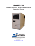
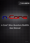
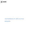
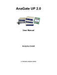
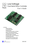
n-Core® Sirius A Device
User Manual
Rev. 20130823
Sirius A
User Manual
Table of contents
1.
Introduction ....................................................................................................................... 2
2.
Technical features ............................................................................................................ 3
3.
Pinout ................................................................................................................................. 4
4.
Power supply ..................................................................................................................... 5
4.1.
On/Off mode ................................................................................................................................................. 5
4.2.
Reset ................................................................................................................................................................ 5
5.
Input and output interfaces ............................................................................................. 5
5.1.
GPO ................................................................................................................................................................. 6
5.2.
GPI ................................................................................................................................................................... 6
5.3.
ADC ................................................................................................................................................................. 7
5.4.
I2C..................................................................................................................................................................... 8
5.5.
SPI ..................................................................................................................................................................... 8
5.6.
USART ............................................................................................................................................................... 9
5.6.1.
USB ........................................................................................................................................................... 9
5.6.2.
DB-9/RS-232 ............................................................................................................................................ 9
5.7.
LED ................................................................................................................................................................. 10
6.
Radio ................................................................................................................................ 10
7.
Firmware updates ........................................................................................................... 10
8.
Accessories ..................................................................................................................... 11
9.
Recommendations of use and security ....................................................................... 11
10. Additional information ................................................................................................... 12
1
Sirius A
User Manual
1. Introduction
GPO
GPI
ADC
I2C
USART (USB)
USART (RS-232)
RELAYS (GPO)
Sirius A is a radio frequency device that offers a total solution to build wireless networks based on the IEEE
802.15.4/ZigBee™ standard in a fast and easy way.
Its robust design provides an extraordinary connectivity and versatility to adapt to a wide range of
applications. It has several communication ports and input/output interfaces, which allows integrating a
great number of external devices such as, for example, sensors, actuators or even computers, among
others.
Sirius A forms part of the n-Core® platform, developed by Nebusens. n-Core® offers a set of hardware and
software tools capable for covering all your necessities of development and deployment of wireless
networks based on the IEEE 802.15.4/ZigBee™ standard.
For more information about the n-Core® platform, please visit www.nebusens.com
2
Sirius A
User Manual
2. Technical features
Independent power supply (DC IN)
Mini-USB power supply
Power switch
Dimensions
Model
Frequency
Flash
RAM
EEPROM
External EEPROM
Transceiver
Frequency band
Number of channels
Channel spacing (USA)
Maximum power transmission
(software-controlled)
Sensitivity
Data transmission rate
Transceiver
Frequency band
Number of channels
Channel spacing
Maximum power transmission
(software-controlled)
Sensitivity
Data transmission rate
UART through USB/DB-9
SPI
I2C Master (pull-up)
Programming port
Opto-coupled digital outputs (x4)
Opto-coupled digital inputs (x4)
ADC (x2)
Relay sockets (x2)
UART through USB
UART through DB-9
LED (x2)
Electrical characteristics
5 – 9V
5V
ON/OFF
Physical characteristics
111.8 x 107.7 x 26.3 mm
Micro-controller
ATMEGA1281V
8MHz
128KB
8KB
4KB
256KB (AT25F2048)
Radio
900MHz
AT86RF212
868 to 868.6MHz (Europe)
902 to 928MHz (USA)
1 (Europe), 10 (USA)
2MHz
+10dBm
-110dBm
20 – 100Kbps (Europe)
40 – 250Kbps (USA)
2.4GHz
AT86RF231
2405 to 2480MHz
16
5MHz
+15dBm
-101dBm
250Kbps
Connectivity
1: Manual/SW selection
2: UART through USB/DB-9
10-pin connector
Mini-JTAG
TTL-CMOS compatible
0 – 5V, 50mA. Independent external power supply
TTL-CMOS compatible
0 – 6V, 0 – 50mA
0 – 1.25V
SPDT: N.C., COM, N.O.
Test: 12V@2A
Silabs CP2103 Virtual Com Port
RS-232 (TXD, RXD, CTS, RTS, DTR)
Green/Red
3
Sirius A
User Manual
3. Pinout
1
2
3
4
5
6
7
8
9
10
11
12
13
14
15
16
17
18
19
Block E2
GPO_1
GPO_2
GPO_3
GPO_4
GPO_VCC_IN
GND
GND
GPI_1
GPI_2
GPI_3
GPI_4
ADC_2
ADC_1
GND
GND
I2C SDA
I2C SCL
5V IN
GND
1
2
3
4
5
6
7
8
9
10
1
2
3
Block P2
3.3 V output (controlled)
I2C SDA
SPI_CLK
I2C SCL
SPI_MOSI
ADC_3
SPI_MISO
3.3 V output (permanent)
3.3 V (USB-dependent)
GND
Block E1 (RLY1)
COM
N.C.
N.O.
4
Block P6
1
2
3
4
5
6
7
8
9
10
1
2
3
TCK
GND
TDO
3.3 V output (permanent)
TMS
RESET
N/C
N/C
TDI
GND
Block E1 (RLY2)
COM.
N.C.
N.O.
Sirius A
User Manual
4. Power supply
18-19
Sirius A device has two alternatives for power supply:
2-pole connector in block E2 (pins 18-19): 5 – 9V DC.
Type B-Mini USB connector in block E1: 5V DC.
USB
Both connections can be established simultaneously, without
influencing in the normal operation of the device.
4.1. On/Off mode
On/Off button of Sirius A device is placed in block E1. This switch
allows eliminating completely the power supply of the device.
1. Device switched off
2. Device switched on
1
2
4.2. Reset
Reset button of Sirius A device is placed in block E2. This button
reinitiates the routines programmed in the device, without
affecting data stored in EEPROM.
5. Input and output interfaces
Sirius A device has the following input and output interfaces:
4 opto-coupled digital outputs (GPO)
2 relay ports (GPO) SPDT configuration
4 opto-coupled digital inputs (GPI)
2 software-configurable as IRQs
3 analog-to-digital converter (ADC)
2 general-purpose
1 in DC-IN
2 LEDs (green and red)
1 I2C bus (internal pull-up)
1 SPI bus
1 USART accessible from outside
USB (Virtual Com Port)
RS-232 (DB-9)
All input and output interfaces available in Sirius A device are next described.
5
Sirius A
User Manual
5.1. GPO
Sirius A device has four general-purpose opto-coupled
digital outputs (LTV847S1), accessible from the block E2
(pins 1 - 4).
Voltage and current characteristics for each GPO are
determined by the transistors of the opto-coupler LTV847S.
Next, it is shown the connections for each of the outputs.
IMPORTANT NOTE: In order to use the GPOs is necessary
that reference pins (GND) of both the Sirius A device
(block E2, pins 6 and 7) and the input device (for
example, an actuator) are connected to each other.
The GPO_VCC_IN (block E2, pin 5) is the union of all the collectors of the opto-transistors of the LTV847S.
Each GPO output corresponds with the emitter of an opto-transitor of the LTV847S. In order to activate the
GPO is necessary to supply a voltage between 3.3V and 5V (recommended) to GPO_VCC_IN input. This
voltage will be transmitted to each GPO, considering the losses of each LTV847S opto-transistor.
5.2. GPI
Sirius A device has four general-purpose opto-coupled
digital inputs (LTV847S1), accessible from the block E2 (pins
8 - 11). GPI3 (pin 10) and GPI4 (pin 11) can be configured
as external interruptions (IRQs).
Voltage and current characteristics for each GPI are
determined by the LEDs of the opto-coupler LTV847S.
Next, it is shown the connections for each of the opto-coupled digital inputs.
1 http://www.us.liteon.com/downloads/LTV-817-827-847.PDF
6
Sirius A
User Manual
IMPORTANT NOTE: In order to use the GPI is necessary
that reference pins (GND) of both the Sirius A device
(block E2, pins 6 and 7) and the input device (for
example, a sensor) are connected to each other.
5.3. ADC
Sirius A device has three analog-to-digital converters. Two
of them are accessible from the block E2. ADC_1 and
ADC_2 are for general purposes (pins 12 and 13). ADC_0 is
connected directly to DC-IN (pin 18), allowing the
monitoring of the voltage used to power the device.
The reference voltage of the microcontroller is 1.25V. The
voltage range for ADC_Xexternal input is from 0V to 3.75V.
Next, it is shown the connections of analog-to-digital
converters accessible from outside in the block E2.
This type of connection implies a difference between
the voltage supplied to the external ADC input
(ADC_Xexternal) and the voltage registered by the
microcontroller
in
the
internal
ADC
input
(ADC_Xinternal). The relation between both is given by
the expression:
𝑨𝑫𝑪𝑿𝒊𝒏𝒕𝒆𝒓𝒏𝒂𝒍 =
𝑨𝑫𝑪_𝑿𝒆𝒙𝒕𝒆𝒓𝒏𝒂𝒍
𝟑
A similar behavior is observed for the analog-to-digital converter (ADC_0)
connected to the DC-IN power supply. Therefore, the relation between the
power supply voltage and the voltage read at ADC_0 can be calculated as:
𝑨𝑫𝑪𝟎𝒊𝒏𝒕𝒆𝒓𝒏𝒂𝒍 =
𝑽𝑪𝑪_𝑰𝑵
𝟏𝟏
IMPORTANT NOTE: In order to use the ADC is necessary
that reference pins (GND) of both the Sirius A device
(block E2, pin 14) and the input device (for example, a
sensor) are connected to each other.
7
Sirius A
User Manual
5.4. I2C
Sirius A device has an internally pulled-up I2C bus,
accessible from the block E2 (pins 15 - 17) and from the
internal block P2 (pins 2 - 4).
Electrical and protocol characteristics of I 2C bus are
determined by the specifications of the ATmega1281V®2
microcontroller.
I2C_SDA (block E2, pin 16, and block P2, pin 2) and
I2C_SCL (block E2, pin 17, and block P2, pin 4) lines have
internal pull-up as is shown below:
IMPORTANT NOTE: In order to use the I2C bus is
necessary that reference pins (GND) of both the Sirius A
device (block E2, pin 15) and the input device (for
example, a sensor) are connected to each other.
5.5. SPI
Sirius A device has a SPI bus, accessible from the block P2
(pins 3, 5 and 7).
Electrical and protocol characteristics of SPI bus are
associated to the specifications of the ATmega1281V ®3
microcontroller.
IMPORTANT NOTE: In order to use the SPI bus is
necessary that reference pins (GND) of both the Sirius A
device (block P2, pin 10) and the input device (for
example, a sensor) are connected to each other.
2
3
http://www.atmel.com/dyn/resources/prod_documents/doc2549.pdf (section 12.3.4 Alternate Functions of Port D, p. 83; section 30. Electrical Characteristics, p. 367).
http://www.atmel.com/dyn/resources/prod_documents/doc2549.pdf (section 13.3.2 Alternate Functions of Port B, p. 79).
8
Sirius A
User Manual
5.6. USART
Sirius A device has a USART serial communications port,
accessible from the block E1 through USB and RS-232 ports.
USART can be used to communicate the Sirius A device
with other devices that have serial communication
capacities, for example, a PC. Likewise, USART can also be
used to update the device firmware as described in
Section 6 of this manual.
Access to USART is exclusive for each port, so they cannot
be used simultaneously. Selection of the active port is
done through the switch SW2 (USB/DB-9). SW2 (Man/uC)
must be always in position 0.
Bit rate
Data bits
Parity
Stop bits
Flow control
9600 bps – 115200 bps
8
None
1
Hardware/None
SW2 (Man/uC)
0
0
SW2 (USB/DB-9)
0
1
Selection
USB
DB-9
5.6.1. USB
The USART1 of the ATmega1281V® microcontroller in Sirius A
device is connected to USB port through Silabs USB-Serial
converter, model CP21034.
This port is recognized by the operating system, such as Windows®, as a virtual serial port (Virtual Com Port)5,
and it allows supplying power to the Sirius A device simultaneously to the establishment of the
communication with it.
5.6.2. DB-9/RS-232
The USART1 of the microcontroller ATmega1281V ® in Sirius A
device is also connected to a DB-9 port through a levelconverter, allowing connections with any device that
accomplishes RS-232 standard.
Configuration of DB-9 port pins corresponds to a DCE (Data Circuit-terminating Equipment). Therefore, a
null-modem cable is necessary in order to connect the Sirius A device to a PC.
1
2
3
4
5
6
7
8
9
4
http://www.silabs.com/support/pages/support.aspx?ProductFamily=USB%20to%20UART
5 http://www.silabs.com/products/mcu/Pages/USBtoUARTBridgeVCPDrivers.aspx
9
NC
RXD
TXD
NC
GND
DSR
RTS
CTS
NC
Sirius A
User Manual
5.7. LED
Sirius A device has 2 LEDs placed in block E1.
Green LED: connected to GPIO_1 of the microcontroller.
Red LED: connected to GPIO_0 of the microcontroller.
By default, LEDs are configured as detailed below:
Red LED fast blinking: device is looking for a ZigBee™ network to join.
Red LED sporadic blinking: device is sending Node Alive6 signals, which indicate that the device is
connected to the ZigBee™ network.
Green LED fixed on7: device is connected to a ZigBee™ network.
When n-Core® locating functions are used, both LEDs remain switched off and blink simultaneously
when the device sends a tags table6.
6. Radio
Sirius A devices include a transceiver that implements the IEEE 802.15.4/ZigBee™ standard. The power of the
signal can be configured by software, by means of n-Core® development API6.
Types of antenna:
Model SA2400: Internal ceramic antenna.
Model SA900-1: Internal ceramic antenna.
Model SA900-2: External antenna with RPSMA connector.
Transceiver:
Model SA2400: AT86RF231 + amplifier (up to +15dbm).
Models SA900-1 and SA900-2: AT86RF212.
7. Firmware updates
Sirius A firmware's updates optimize device performance, fix bugs and, in some cases, add new
functionalities.
In order to update the device's firmware in a safe way, please, download the n-Core® update package
and follow the instructions of use carefully. The update package can be downloaded from the support
section at www.nebusens.com
IMPORTANT NOTE: during the firmware update, it is necessary
to ensure the power supply in order to prevent any damage or
data loss. See section 3 of this manual.
6
For further information, please, consult the n-Core® development API reference at www.nebusens.com
7
It is possible that both LED are turned off and the device is still connected to the ZigBee™ network. This could happen because of some routines loaded into the device.
10
Sirius A
User Manual
8. Accessories
The following accessories can be used along with Sirius A devices.
2, 3 and 11-pole connectors:
Terminal block Weidmüller 3.81 pitch / Camden Electronics 3.81pitch
(CTB92HE).
External power supplies:
Power supply through DC-IN:
5 - 9VCC@300mA + 2-pole connector
Power supply through USB:
Compatible with USB (>300mA).
USB data cable:
USB-A – Mini USB-B Cable.
9. Recommendations of use and security
Please, follow the next indications in order to obtain the maximum performance and to use Sirius A device in
a safe way:
Avoid placing metallic objects near the device as far as possible.
Architectonic elements, such as metallic walls, doors, railings, pipes, concrete walls, among many
others, can affect signal quality and, therefore, the maximum distance of communication between
devices.
Do not wet the device.
Do not store or make use of the device in atmospheres with a high humidity rate (70% as maximum).
Do not expose the device to heat sources or directly to the sun.
Avoid short-circuiting connections.
Pay special attention to relay output connections, because it could cause a short circuit in the
device to be controlled.
Do not apply to the device voltages and currents out of maximum and minimum rates
recommended in this manual (both in power supply and input/output ports, as well as
communication buses).
Use an appropriate external power supply. The product must only work with the type of power
supply indicated in this manual. If you are not sure about the type of the required power supply,
please consult the manufacturer.
Avoid manipulating any element of the device not described in this manual, because the warranty
could be invalidated and the equipment could be damaged permanently.
Do not use this product in gas stations, fuel tanks, chemical plants or places where demolition
operations are being carried out or near potentially explosive atmospheres, such as re-fuelling areas,
fuel tanks, under boat decks, chemical plants, facilities of transference or storage of fuel or chemical
agents and areas where the air contains chemistries or particles, such as grain, metallic dust or dust.
Please, consult the pertinent preventive measures before using this device in these kinds of zones.
11
Sirius A
User Manual
The use of accessories unapproved by the manufacturer could damage the equipment, break local
laws and invalidate the warranty.
This product works in approved bands for the use in presence of medical, industrial and scientific
equipment (ISM band), however, in case of doubt avoid the use of the device until being
completely sure of the absence of risk derived from its use in the presence of this type of equipment.
Use only the antenna that is delivered with the device. The use of modified or unauthorized
antennas can reduce the quality of the communication and damage the equipment, besides
break local regulations of your country.
10. Additional information
Disclaimer
Nebusens believes that all information is correct and accurate at the time of issue. Nebusens reserves the
right to make changes to this product without prior notice. Please visit Nebusens website
(www.nebusens.com) for the latest available version.
Nebusens does not assume any responsibility for the use of the described product or convey any license
under its patent rights.
Nebusens warrants performance of its products to the specifications applicable at the time of sale in
accordance with the sale and use conditions of n-Core®. You can check these conditions at the Nebusens
website (www.nebusens.com).
Trademarks
n-Core® and related naming and logos are trademarks of Nebusens, S.L. All other product names, trade
names, trademarks, logos or service names are the property of their respective owners.
Technical Support
Technical support is provided by Nebusens, S.L. on demand and in accordance to sale and use conditions
agreed. You can check these conditions at the Nebusens website (www.nebusens.com).
We provide you with a support forum (support.nebusens.com) for any question related to the n-Core®
platform.
Waste and recycling
When the device reaches the end of its life cycle, it will have to be deposited in a point of recycling for
electronic equipment. The equipment will not have to be deposited in the points of urban garbage
collection. Please, go to a specialized point. Your distributor will indicate the most appropriate way to
proceed with the recycle of the device.
12