1
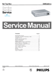
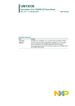
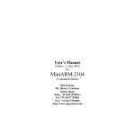
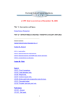
UM10349 Contact smart card reader chips evaluation with CAKE80xx_MBA Rev. 1.0 — 1 October 2014 User manual Document information Info Content Keywords TDA Eval board, Smart card reader Abstract This document describes the way to use the Cake80xx_MBA mother board: power supply, protocols, plug of the daughter boards, firmware UM10349 NXP Semiconductors Contact smart card reader chips evaluation with CAKE80xx_MBA Revision history Rev Date Description 1.0 0.3 0.2 0 First official release Add TDA8037 Add EMV Loopback mechanism Draft 20141001 20131008 20101116 20090313 Contact information For more information, please visit: http://www.nxp.com For sales office addresses, please send an email to: [email protected] UM10349 User manual All information provided in this document is subject to legal disclaimers. Rev. 1.0 — 1 October 2014 © NXP B.V. 2014. All rights reserved. 2 of 33 UM10349 NXP Semiconductors Contact smart card reader chips evaluation with CAKE80xx_MBA 1. Board presentation The Cake80xx_MBA is a mother board dedicated to the evaluation of the NXP smart card reader front end devices. The following devices are compliant with the mother board: • TDA8025 with the Cake8025_01_D daughter board • TDA8026 with the Cake8026_02_D daughter board • TDA8034 with the Cake8034_0X_D daughter boards (one for each package) • TDA8024 with the Cake8024_11_D (TDA8024TT) and Cake8024_12_D (TDA8024T) daughter boards • TDA8020 with the Cake8020_07_D daughter board • TDA8023 with the Cake8023_06_D daughter board • TDA8035 with the Cake8035_01_D daughter board • TDA8037 with the Cake8037T and Cake8037TT daughter board Fig 1. Cake80xx_MBA UM10349 User manual All information provided in this document is subject to legal disclaimers. Rev. 1.0 — 1 October 2014 © NXP B.V. 2014. All rights reserved. 3 of 33 UM10349 NXP Semiconductors Contact smart card reader chips evaluation with CAKE80xx_MBA 1.1 Board architecture The following figure shows how the Cake80xxMBA drives TDA daughter boards. Power supply RS232 VDD VDD CPU LPC2212 Configuration ISO7816 management TDA8007 (ISO 7816 UART) Config J1 J4 Tested TDA IO IOUC IOAUX Cake80xxMBA Mother Board Fig 2. VCC CLK RST Cake TDA Daugher board Cake80xxMBA evaluation architecture The TDA8007 on the mother board is used as an ISO7816 UART interface. Then the host CPU drives the evaluated TDA directly for the configuration and activation management, and through the TDA8007 for the smart card communication (data over IO line). UM10349 User manual All information provided in this document is subject to legal disclaimers. Rev. 1.0 — 1 October 2014 © NXP B.V. 2014. All rights reserved. 4 of 33 UM10349 NXP Semiconductors Contact smart card reader chips evaluation with CAKE80xx_MBA 1.2 Board connections The Mother board must be supplied and connected to the host to be used. 1.2.1 Power supply The power is supplied through the Jack connector J12. This board must be supplied with 5V. On the Jack connector the 5V must be inside the connector while the ground is on the external connection. 1.2.2 Computer connection The connection to the computer is made through an RS232 straight serial cable connected on J5. 1.2.3 Daughter boards connections The daughter boards must be plugged on the HE10 connectors J1 to J4. The daughter boards must always be placed so that the main smart card connector is available from the side opposed to the RS232 connector, as shown in the next figure. Power Supply RS232 J5 Cake80xx_MBA J12 J3 J1 J4 J2 Main card insertion Fig 3. Daughter board - Card connector position With respect to this card connector position, the following figures give the position of the different daughter boards. UM10349 User manual All information provided in this document is subject to legal disclaimers. Rev. 1.0 — 1 October 2014 © NXP B.V. 2014. All rights reserved. 5 of 33 UM10349 NXP Semiconductors Contact smart card reader chips evaluation with CAKE80xx_MBA Power Supply J5 J3 J3 J1 J1 Cake8026 Cake8023 Cake8020 J4 J4 J2 J2 J3 Cake8034 Cake8025 Cake8024 Cake8035 Cake8037 J4 J4 Main card insertion a. Cake8026 connection RS232 J5 J12 Cake80xx_MBA J12 Cake80xx_MBA Power Supply RS232 J1 J2 J2 Main card insertion b. Cake8034 or Cake8025 connection Fig 4. Daughter boards position • The Cake8034 and Cake8024 use only two connectors: J2 and J4. J4 is a 10 pins connector while the other (J1 to J3) are only 8 pins. • Cake8025, Cake8035 and Cake8037 use J2 and J4 as well, but only the 8 lower pins of J4 are needed. • Cake8026, Cake8023 and Cake8020 must be plugged on the 4 connectors J1 to J4. UM10349 User manual All information provided in this document is subject to legal disclaimers. Rev. 1.0 — 1 October 2014 © NXP B.V. 2014. All rights reserved. 6 of 33 UM10349 NXP Semiconductors Contact smart card reader chips evaluation with CAKE80xx_MBA 2. Communication 2.1 ALPAR Protocol The communication between the host controller and the Cake80xx_MBA obeys to a protocol named ALPAR. This protocol encapsulates the useful data of a message in an invariant frame structure and defines a dialog structure of messages exchanges. Data is exchanged between the host controller and the mother board in blocks, each made up of binary characters on one byte: 4 header characters 0 to 506 data characters (C-APDU or R-APDU) 1 LRC character 4 bytes Header Fig 5. 0 to 506 bytes C-APDU or R-APDU Information field 1 byte LRC Frame structure The 4 header bytes include the following bytes: st 1 byte A 1 1 0 0 0 0 0 nd 2 byte rd 3 byte th 4 byte Data length to transmit excluding Command byte header and LRC st A=0: Acknowledge of the frame (1 byte = 60) st A=1: Nack of the frame (message with a status error, 1 byte = E0) Fig 6. Frame structure The LRC (Longitudinal Redundancy Check) byte is such that the exclusive-oring of all bytes including LRC is null. 2.1.1 General dialog structure The host controller is the master for the transmission; each command from the master is followed by an answer from TDACake80xx_MBA including the same command byte as the input command. However, in some cases (card insertion or extraction, a time out detection on Rx line or an automatic emergency deactivation of the card) the Cake80xx_MBA is able to initiate an exchange. UM10349 User manual All information provided in this document is subject to legal disclaimers. Rev. 1.0 — 1 October 2014 © NXP B.V. 2014. All rights reserved. 7 of 33 UM10349 NXP Semiconductors Contact smart card reader chips evaluation with CAKE80xx_MBA 2.1.1.1 Successful command System to TDA8029: 60 XX XX YY nnnnnnnnnnnnnnnnnnnn ZZ ACK length code Data (C-APDU) LRC TDA8029 to System: 60 UU UU YY (1) mmmmmmmmmmmmmm TT ACK length code Data (R-APDU) LRC (1) The same command byte YY is returned in the answer from TDA8029. Fig 7. Successful command frame description 2.1.1.2 Unsuccessful command System to TDA8029: 60 XX XX YY nnnnnnnnnnnnnnnnnnnn ZZ ACK length code Data (C-APDU) LRC TDA8029 to System: E0 UU UU YY SS (1) TT NACK length code Status LRC (1) In that case, the status contains the error code information (see error list) Fig 8. Unsuccessful command frames 2.1.1.3 Answer with an acknowledge (power_off, idle_mode, power_down_mode) System to TDA8029 (example: power_off): 60 00 00 4D 2D ACK Length code LRC TDA8029 to System: 60 00 00 4D 2D ACK Length code LRC (1) In the case where the answer is an acknowledge of the command, the TDA8029 sends back a frame with the same content of the command. Fig 9. Acknowledge frame UM10349 User manual All information provided in this document is subject to legal disclaimers. Rev. 1.0 — 1 October 2014 © NXP B.V. 2014. All rights reserved. 8 of 33 UM10349 NXP Semiconductors Contact smart card reader chips evaluation with CAKE80xx_MBA 2.2 Commands 2.2.1 General commands The following command bytes are available (listed in numerical order): Table 1. Command summary Command Code Description card_command (APDU) 00H Sends an APDU to the activated smart card check_pres_card 09H Check the selected card presence send_num_mask 0AH Reads the firmware version set_card_baud_rate 0BH Sets the baudrate of the activated smart card ifsd_request 0CH Request an IFSD change for the activated smart card communication Set_serial_baud_rate 0DH Changes the baudrate for host communication show_fidi 0EH Displays the current FiDi set_serial_timeout 0FH Sets the timeout for the serial connexion negotiate (PPS) 10H Initiates a parameter change for t=0 set_clock_card 11H Selects the division for the smart card clock tda_write_i2c 2BH Write to a TDA connected to the CPU through I²C interface tda_read_i2c 2CH Reads from a TDA connected to the CPU through I²C interface start_EMV_loopback 2FH Launch the EMV loopback process. Blocking function that does not return power_off 4DH Deactivates the current smart card select_device 67H Selects the connected TDA daughter board power_up_1.8V 68H Activates the card with VCC=1.8V select_card 6AH Selects the smart card to access power_up_3V 6DH Activates the card with VCC=3V power_up_5V 6DH Activates the card with VCC=5V set_nad A5H Sets the NAD parameter for T=1 communication idle_mode A9H Sets the smart card in idle mode (activated with lower consumption) get_reader_status AAH Displays information about the current state of the reader UM10349 User manual All information provided in this document is subject to legal disclaimers. Rev. 1.0 — 1 October 2014 © NXP B.V. 2014. All rights reserved. 9 of 33 UM10349 NXP Semiconductors Contact smart card reader chips evaluation with CAKE80xx_MBA Table 2. Outgoing commands (only) Command Code Parameter Description Card_extraction A0H X0H Card_insertion A0H X1H These commands are sent as soon as a card is inserted or extracted without any command coming from the system. These commands use the same operating code but the extra parameter gives the additional information. The ‘X’ in the parameter (high nibble) is the number of the card that has been inserted or extracted. Card deactivated XXH 40H The card is deactivated due to a hardware problem (short on Vcc, overcurrent) Time out XXH FFH Time out problem on (Cake80xx_MBA) Rx line This command is used in order to warn the host controller that the last communication has broken down (time out problem) so that the Rx line of Cake80xx_MBA does not remain blocked. The time out condition is a silence greater than 10 ms in the host command frame. Frame lost XXH F1H An unexpected host controller command frame has been received by the Cake80xx_MBA while it was busy to process a previous command frame. In the last three commands, the code value is the previous code value used during a normal exchange. 2.3 Error list The error list gives the status code identification and a brief signification of the status error code. Table 3. UM10349 User manual List of error codes Status code Meaning 08H Length of the data buffer too short 20H Wrong APDU 21H Too short APDU 22H Card mute now (during T=1 exchange) 24H Bad NAD 25H Bad LRC 26H Resynchronized 27H Chain aborted 29H Overflow from card 30H Non negotiable mode (TA2 present) 31H Protocol is neither T=0 nor T=1 (negotiate command) 32H T=1 is not accepted (negotiate command) All information provided in this document is subject to legal disclaimers. Rev. 1.0 — 1 October 2014 © NXP B.V. 2014. All rights reserved. 10 of 33 UM10349 NXP Semiconductors Contact smart card reader chips evaluation with CAKE80xx_MBA UM10349 User manual Status code Meaning 33H PPS answer is different from PPS request 34H Error on PCK (negotiate command) 35H Bad parameter in command 38H TB3 absent 39H PPS not accepted (no answer from card) 3BH Early answer of the card during the activation 40H Card Deactivated 55H Unknown command 80H Card mute (after power on) 81H Time out (waiting time exceeded) 83H 4 parity errors in reception 84H 4 parity errors in transmission 86H Bad FiDi 88H ATR duration greater than 19200 etus (E.M.V.) 89H CWI not supported (E.M.V.) 8AH BWI not supported (E.M.V.) 8BH WI (Work waiting time) not supported (E.M.V.) 8CH TC3 not accepted (E.M.V.) 8DH Parity error during ATR 92H Specific mode byte TA2 with b5 byte=1 93H TB1 absent during a cold reset (E.M.V.) 94H TB1different from 00 during a cold reset (E.M.V.) 95H IFSC<10H or IFSC=FFH 96H Wrong TDi 97H TB2 is present in the ATR (E.M.V.) 98H TC1 is not compatible with CWT 99H IFSD not accepted A0H Procedure byte error C0H Card absent C3H Checksum error All information provided in this document is subject to legal disclaimers. Rev. 1.0 — 1 October 2014 © NXP B.V. 2014. All rights reserved. 11 of 33 UM10349 NXP Semiconductors Contact smart card reader chips evaluation with CAKE80xx_MBA UM10349 User manual Status code Meaning C6H ATR not supported E0H Card error (bad card selected) E1H Card clock frequency not accepted (after a set_clock_card command) E2H UART overflow E3H Supply voltage drop-off E4H Temperature alarm E9H Framing error F0H Serial LRC error F1H At least one command frame has been lost FFH Serial time out All information provided in this document is subject to legal disclaimers. Rev. 1.0 — 1 October 2014 © NXP B.V. 2014. All rights reserved. 12 of 33 UM10349 NXP Semiconductors Contact smart card reader chips evaluation with CAKE80xx_MBA 2.4 Commands description 2.4.1 General commands 2.4.1.1 send_num_mask This command is used to identify the software version which is flashed in the Cake80xx_MBA CPU. For example the current software can be coded as: “ARMTDA 1.0 TDA8026” The first string represents the firmware name, then the version is given, and finally the name of the current used daughter board is displayed. System to CAKE80XX: 60 00 00 0A 6A CAKE80XX to System: 60 00 01 0A 41 52 4D 54 44 41 20 31 2E 30 20 54 4D 41 38 30 32 36 LRC 2.4.1.2 Select_device This command selects the device type plugged with the daughter board. When executed, this command changes the device to the one chosen and performs an initialization of the microcontroller and the TDA plugged. The result of the device switch can be seen in the mask version: After the firmware version, the used device is displayed. The following parameters are used by this command: • 00H: Selects the TDA8026 • 01H: Selects the TDA8025 • 02H: Selects the TDA8034T (SO16 package) • 03H: Selects the TDA8034HN (HVQFN24 package) • 04H: Selects the TDA8020 • 05H: Selects the TDA8023 • 06H: Selects the TDA8024 • 07H: Selects the TDA8035 • 08H: Selects the TDA8037 System to CAKE80XX: 60 00 01 67 01 06 CAKE80XX to System: 60 00 00 67 07 2.4.1.3 check_card_presence This command is used to check the presence of a card. System to CAKE80XX: 60 00 00 09 69 CAKE80XX to System: 60 00 01 09 PRES LRC Where PRES indicates the presence of the selected slot (00 if there is no card, 01 if a card is present). UM10349 User manual All information provided in this document is subject to legal disclaimers. Rev. 1.0 — 1 October 2014 © NXP B.V. 2014. All rights reserved. 13 of 33 UM10349 NXP Semiconductors Contact smart card reader chips evaluation with CAKE80xx_MBA 2.4.1.4 get_reader_status This command is used to check the status of the reader. System to CAKE80XX: 60 00 00 AA CA CAKE80XX to System: 60 00 01 AA EMV PRO FIDI UX CS VER MTH YR LRC Where: 2.4.1.5 • EMV: emv state • PRO: protocol type. • FIDI: current FiDi • UX: UX parameter • CS: Cards 1 to 4 state. High nibble=Presence, low nibble=activation • VER: Actual version number. • MTH: Month of the actual version • YR: Year of the actual version set_serial_baud_rate This command is used for changing the baud rate onto the serial link between the host and the interface card. The default value is set to 38400 baud. A parameter has to be transmitted in order to choose the baud rate: System to CAKE80XX: CAKE80XX to System: Table 4. 60 00 01 0D PAR LRC 60 00 00 0D 6D Baud rate parameter Baud rate (Baud) Parameter 4800 00 9600 01 19200 02 38400 03 57600 04 76800 05 115200 06 After a baud rate change, the new value takes place for the next command sent by the host. 2.4.1.6 serial_time_out This command is sent from CAKE80XX to the host controller if, during a transmission from the host controller to CAKE80XX, the time interval between 2 characters exceeds 10ms. This timing is calculated between each character of a frame, starts after the first character, and is disabled after the last character of the frame. This feature has been implemented in order to avoid any blocking of the transmission line between the host controller and CAKE80XX. CAKE80XX to System: E0 00 01 6F FF 71 UM10349 User manual All information provided in this document is subject to legal disclaimers. Rev. 1.0 — 1 October 2014 © NXP B.V. 2014. All rights reserved. 14 of 33 UM10349 NXP Semiconductors Contact smart card reader chips evaluation with CAKE80xx_MBA 2.4.2 power_up commands There are three different power up commands (5V, 3V , 1.8V). Two of them (power_up_3V and power_up_5V) have to be followed by a parameter: 2.4.2.1 00H indicates that all the parameters of the ATR of the card compliant with ISO7816-3 will be taken into account. 01H indicates that only the ATR of cards whose parameters are inside the E.M.V. 4.2 specification scope will be taken into account; cards having an ATR which does not comply with E.M.V. 4.2 requirements will be rejected. power_up_5V This command allows activating the card at a VCC of 5V. All the signals going to the card will be referenced to this VCC. An activation sequence is processed following the ISO7816-3 normalization (VCC is rising, I/O is enabled, CLK is started, and RST is processed). If the card answers to this command, the answer will content all the ATR parameters; these parameters are memorized in CAKE80XX and will be taken into account during the whole card session (till the card is deactivated or till a warm reset is processed). The structure of the answer is the following: System to CAKE80XX 60 AC K 00 01 Length 6E code 01 E.M.V . 0F LRC CAKE80XX to System 60 AC K XX XX Length E 6 code nnnnnnnnnnnnnnnnnnnn ATR parameters ZZ LRC Fig 10. power_up_5V frame exchange If the card is in specific mode, CAKE80XX will process the next command directly using the new interface parameters of this specific mode. If the card proposes a different Fi/Di in the ATR than the default value (Fi/Di=372), it is up to the application to make a PPS command by using the negotiate command. If the card proposes 2 different protocols in its ATR, it is up to the application to make a PPS command by using the negotiate command. If the card does not answer to the reset, a status giving an error code is returned to the application. In the case of E.M.V. compliant power up, if the card is using T=1 protocol, just after having received the ATR, CAKE80XX sends an IFSD request to the card indicating that the reader can manage a data buffer of 254 bytes (FEH). The power_up_5V command can be used to generate a warm reset if the card is already activated. UM10349 User manual All information provided in this document is subject to legal disclaimers. Rev. 1.0 — 1 October 2014 © NXP B.V. 2014. All rights reserved. 15 of 33 UM10349 NXP Semiconductors Contact smart card reader chips evaluation with CAKE80xx_MBA 2.4.2.2 power_up_3V This command allows activating the card at a VCC of 3V. Every signal going to the card will be referenced to this VCC. See power_up_5V for the other characteristics. 2.4.2.3 power_up_1.8V This command allows activating the card at a VCC of 1.8V. Every signal going to the card will be referenced to this VCC. See power_up_5V for the other characteristics. 2.4.3 power_off This command is used to deactivate the card whatever it has been activated for 3V or 5V operation. A deactivation sequence is processed following the ISO 7816-3 normalization in about 100µs. System to CAKE80XX: 60 00 00 4D 2D CAKE80XX to System: 60 00 00 4D 2D 2.4.4 card_command (APDU) This command is used to transmit card commands under APDU format from system to CAKE80XX whatever T=0 or T=1 protocol are used. Short or extended commands (see limitations in §8.1) can be used. An answer to such a command is also made in APDU format from CAKE80XX to the system. Example: System to CAKE80XX: 60 00 07 00 00 A4 00 00 02 4F 00 8E CAKE80XX to System: 60 00 02 00 90 00 F2 2.4.5 negotiate This command is used to make a PPS (Protocol and Parameter Selection) to the card, if in its ATR the card proposes a different Fi/Di or 2 different protocols. By using this command a PPS will be made to the card with the Fi or Di and protocol type entered as a parameter (PP). It is up to the host to make the correct Fi/Di submission to the card. Example: System to CAKE80XX: 60 00 02 10 PP FD LRC CAKE80XX to System: 60 00 00 10 70 Where FD is the ratio Fi/Di given by TA1 parameter of the ATR and PP is the protocol to be used. If the command is acknowledged, any subsequent exchanges between the card and CAKE80XX will be made by using the new parameters. UM10349 User manual All information provided in this document is subject to legal disclaimers. Rev. 1.0 — 1 October 2014 © NXP B.V. 2014. All rights reserved. 16 of 33 UM10349 NXP Semiconductors Contact smart card reader chips evaluation with CAKE80xx_MBA 2.4.6 Ifsd_request This command is used to send a S(IFS request) block to the card indicating the maximum length of information field of blocks which can be received by the interface device in T=1 protocol. The initial size following the answer to reset is 32 bytes and this size shall be used throughout the rest of the card session or until a new value is negotiated by the terminal by sending a S(IFS request) block to the card. In E.M.V. mode, the IFSD size is automatically negotiated to 254 just after the ATR has been received. System to CAKE80XX: 60 00 01 0C PAR LRC CAKE80XX to System: 60 00 00 0C 6C Where PAR is the IFSD size. 2.4.7 set_clock_card This command is used for changing the card clock frequency. The default value is set to FXTAL/4 which is 3.68625 MHz. A parameter has to be transmitted in order to choose the card clock frequency: System to CAKE80XX: 60 00 01 11 PAR LRC Table 5. set_clock_card parameter Based on a crystal with a frequency equal to 14.745MHz Frequency Parameter Fxtal =14.745MHz 00 Fxtal/2=7.37MHz 02 Fxtal/4=3.68MHz 04 Fxtal/8=1.84MHz 06 After a card clock frequency change, all the waiting times are internally set to the new value. Before applying the requested clock, the compatibility of the frequency with the current Fi used by the card is checked as described in ISO7816-3. For example, if the card has answered in its ATR a Fi parameter of 372 or 558 (fmax ≤ 6MHz), a change of the card clock frequency to Fxtal (14.745MHz) or Fxtal/2 (7.37MHz) will not be processed and an error status will be sent to the application. 2.4.8 card_take_off and card_insertion These two commands are sent directly to the system processor as soon as a card extraction or insertion has occurred. CAKE80XX to System: UM10349 User manual 60 00 01 A0 10 C1 for a card 1 extraction 60 00 01 A0 11 C0 for a card 1 insertion. All information provided in this document is subject to legal disclaimers. Rev. 1.0 — 1 October 2014 © NXP B.V. 2014. All rights reserved. 17 of 33 UM10349 NXP Semiconductors Contact smart card reader chips evaluation with CAKE80xx_MBA 2.4.9 set_card_baud_rate This command is used mainly for cards which are not fully ISO 7816-3 compliant with specific and negotiable modes. As a matter of fact some cards are in specific mode but they do not give TA2 parameter in their answer to reset. So the UART has to be set to the right baud rate by means of this specific command which programs the baud rate. For non ISO baud rates there is a possibility to increase the capability of the reader by setting the bit CKU which divides by 2 the number of clock cycles of the etu and thus doubles the baud rate of the ISO UART. Example: System to CAKE80XX: 60 00 02 0B XX CKU LRC CAKE80XX to System: 60 00 00 0B LRC Where XX is the value of FiDi if CKU=0, the baud rate is defined by FiDi if CKU=1, the baud rate is 2 * the baud rate is defined by FiDi For an etu of 372 clock cycles: XX=FiDi=0x11 prescaler = 31, divider = 12; 31 * 12 = 372, CKU=0. Table 6. Supported baudrates As the baud rates in dark boxes are using CKU bit, they are not reachable when fCLK = fXTAL/1 TA1 CLK/ETU TA1 CLK/ETU TA1 CLK/ETU TA1 CLK/ETU TA1 CLK/ETU 0x01 372 0x31 744 0x54 186 0x95 32 0xC1 1536 0x02 186 0x32 372 0x55 93 0x96 16 0xC2 768 0x03 93 0x33 186 0x56 46.5 0xA1 768 0xC3 384 0x04 46.5 0x34 93 0x58 124 0xA2 384 0xC4 192 0x08 31 0x35 46.5 0x61 1860 0xA3 192 0xC5 96 0x11 372 0x38 62 0x62 930 0xA4 96 0xC6 48 0x12 186 0x41 1116 0x63 465 0xA5 48 0xC8 128 0x13 93 0x42 558 0x64 232.5 0xA8 64 0xD1 2948 0x14 46.5 0x43 279 0x68 155 0xB1 1024 0xD2 1024 0x18 31 0x44 139.5 0x69 93 0xB2 512 0xD3 512 0x21 558 0x48 93 0x91 512 0xB3 256 0xD4 256 0x22 279 0x51 1488 0x92 256 0xB4 128 0xD5 128 0x23 139.5 0x52 744 0x93 128 0xB5 64 0xD6 64 0x28 46.5 0x53 372 0x94 64 0xB6 32 UM10349 User manual All information provided in this document is subject to legal disclaimers. Rev. 1.0 — 1 October 2014 © NXP B.V. 2014. All rights reserved. 18 of 33 UM10349 NXP Semiconductors Contact smart card reader chips evaluation with CAKE80xx_MBA 2.4.10 set_nad This command is used from the application layer in order to specify a SAD (source address) and a DAD (destination address) for a logical connection using T=1 protocol as defined in ISO7816-3. The default value is 00 and will be kept until the send NAD command has been notified to the CAKE80XX. Any NAD submission where SAD and DAD are identical (except 00) will be rejected. If bits b4 or b8 of the NAD required are set to 1 (VPP programming) the NAD will be rejected. The NAD shall be initialized before any information exchange with the card using T=1 protocol, otherwise and error message will be generated. System to CAKE80XX: 60 00 01 A5 NAD LRC CAKE80XX to System: 60 00 00 A5 LRC Where NAD is the new value of NAD immediately taken into account. 2.4.11 TDA_write_i2c This command writes a value on an I²C address if a TDA with I²C interface is connected on the board (e.g.: TDA8026). The answer from the board is an acknowledge. Example: System to CAKE80XX: 60 00 02 2B ADD VAL LRC CAKE80XX to System: 60 00 00 2B LRC Where ADD is the I²C address, and VAL is the value to write. 2.4.12 TDA_write_i2c This command reads a value on an I²C address if a TDA with I²C interface is connected on the board (e.g.: TDA8026). The answer from the board is the read value. Example: System to CAKE80XX: 60 00 01 2C ADD LRC CAKE80XX to System: 60 00 01 2C VAL LRC Where ADD is the I²C address, and VAL is the read value returned. 2.4.13 Start_EMV_Loopback These commands launch the EMV Loopback mechanism. This is a loop which tries to activate the smart card (slot 1) every second. If the card activation is success, then the EMV loopback starts and the full test is performed automatically. At the end, the loop restarts, trying to activate again the smart card. This commands never returns and works by itself. It allows passing a full EMV protocol certification without any action from the user. (But it can display data on the serial link) System to CAKE80XX: 60 00 01 2F LRC CAKE80XX to System: ASCII DATA UM10349 User manual All information provided in this document is subject to legal disclaimers. Rev. 1.0 — 1 October 2014 © NXP B.V. 2014. All rights reserved. 19 of 33 UM10349 NXP Semiconductors Contact smart card reader chips evaluation with CAKE80xx_MBA 3. Embedded firmware The mother board Cake80xxMBA is supplied with a loaded firmware with a protocol interface described in the communication chapter. The loaded firmware may not be the one described in this file but a previous version. If the latest one is required, it must be compiled and loaded using the following description. The source code of this mother board is available as a MSVC solution, provided with an installer: Cake80xxMBAFW_setup.exe. This solution is based on MSVC 2003 for the text editor, but as it’s an ARM embedded software, it uses GNUARM compiler and linker. 3.1 Compiler The GNUARM Compiler can be downloaded from the GNUARM website: www.nxp.com/redirect/gnuarm.com/ The package that has been used to build the Firmware is the GCC-4.1 toolchain for cygwin: http://www.gnuarm.com/bu-2.17_gcc-4.1.1-c-c++_nl-1.14.0_gi-6.5.exe For the project to be built, the GNUARM compilers must be installed in the C:\GNUARM folder. If another folder is chosen, then the GNUARM dir in the Build.mak file must be updated. Fig 11. Build.mak – Compiler path UM10349 User manual All information provided in this document is subject to legal disclaimers. Rev. 1.0 — 1 October 2014 © NXP B.V. 2014. All rights reserved. 20 of 33 UM10349 NXP Semiconductors Contact smart card reader chips evaluation with CAKE80xx_MBA 3.2 Loader Once the Firmware has been built, it can be loaded using LPC2000 Flash Utility which can be downloaded from the NXP website: http://www.nxp.com/documents/other/lpc2000_flash_isp_utility.zip The loader must be configured as follows: Fig 12. LPC200 Flash Utility – Configuration The COM port must be adapted to the one used to connect the Cake80xx_MBA board. The filename is the built hex file. By default, after source code installation, the path is: C:\Program Files\NXP Semiconductors\Cake80xxMBAFirmware\obj\ArmTDA.hex To load the software, follow the steps: • Supply the Cake80xxMBA board, and connect the serial port to the PC COM port • Click on the “Upload to Flash” button under the Flash Utility tool • When the tool asks to reset the board, press and hold the ISP switch of the Cake80xxMBA, then press and release the RST switch, and finally release ISP • Click on OK in the message box of Flash Utility • The load starts After the load is completed, reset the board by pressing the RST switch only, the board restarts with the new FW. UM10349 User manual All information provided in this document is subject to legal disclaimers. Rev. 1.0 — 1 October 2014 © NXP B.V. 2014. All rights reserved. 21 of 33 UM10349 NXP Semiconductors Contact smart card reader chips evaluation with CAKE80xx_MBA 4. Special comments 4.1 Remarks for CAKE8037T and CAKE8037TT Support If you get the Motherboard is not marked CAKE80xx_MBA_01_v2 (or has a blue sticker) on it, the quartz Y1 needs to be changed in order to be able to use the CAKE8037T or the CAKE8037TT. This is because the TDA8037 can only divide the frequency by 1 or 2. The new quartz Y1 needs to be between 4 and 5 MHz. Quartz Y1 Fig 13. Cake80xx_MBA UM10349 User manual All information provided in this document is subject to legal disclaimers. Rev. 1.0 — 1 October 2014 © NXP B.V. 2014. All rights reserved. 22 of 33 UM10349 NXP Semiconductors Contact smart card reader chips evaluation with CAKE80xx_MBA 5. Schematic and layout 5.1 Schematic Fig 14. CAKE80xx_MBA_01_D Schematic part 1 UM10349 User manual All information provided in this document is subject to legal disclaimers. Rev. 1.0 — 1 October 2014 © NXP B.V. 2014. All rights reserved. 23 of 33 UM10349 NXP Semiconductors Contact smart card reader chips evaluation with CAKE80xx_MBA Fig 15. CAKE80xx_MBA_01_D Schematic part 2 UM10349 User manual All information provided in this document is subject to legal disclaimers. Rev. 1.0 — 1 October 2014 © NXP B.V. 2014. All rights reserved. 24 of 33 UM10349 NXP Semiconductors Contact smart card reader chips evaluation with CAKE80xx_MBA Fig 16. CAKE80xx_MBA_01_D Schematic part 3 UM10349 User manual All information provided in this document is subject to legal disclaimers. Rev. 1.0 — 1 October 2014 © NXP B.V. 2014. All rights reserved. 25 of 33 UM10349 NXP Semiconductors Contact smart card reader chips evaluation with CAKE80xx_MBA 5.2 Layout Fig 17. Layout - Top Layer UM10349 User manual All information provided in this document is subject to legal disclaimers. Rev. 1.0 — 1 October 2014 © NXP B.V. 2014. All rights reserved. 26 of 33 UM10349 NXP Semiconductors Contact smart card reader chips evaluation with CAKE80xx_MBA Fig 18. Layout – Bottom Layer UM10349 User manual All information provided in this document is subject to legal disclaimers. Rev. 1.0 — 1 October 2014 © NXP B.V. 2014. All rights reserved. 27 of 33 UM10349 NXP Semiconductors Contact smart card reader chips evaluation with CAKE80xx_MBA 5.3 BOM Fig 19. Bill of materials UM10349 User manual All information provided in this document is subject to legal disclaimers. Rev. 1.0 — 1 October 2014 © NXP B.V. 2014. All rights reserved. 28 of 33 UM10349 NXP Semiconductors Contact smart card reader chips evaluation with CAKE80xx_MBA 6. Legal information 6.1 Definitions Draft — The document is a draft version only. The content is still under internal review and subject to formal approval, which may result in modifications or additions. NXP Semiconductors does not give any representations or warranties as to the accuracy or completeness of information included herein and shall have no liability for the consequences of use of such information. 6.2 Disclaimers Limited warranty and liability — Information in this document is believed to be accurate and reliable. However, NXP Semiconductors does not give any representations or warranties, expressed or implied, as to the accuracy or completeness of such information and shall have no liability for the consequences of use of such information. In no event shall NXP Semiconductors be liable for any indirect, incidental, punitive, special or consequential damages (including - without limitation lost profits, lost savings, business interruption, costs related to the removal or replacement of any products or rework charges) whether or not such damages are based on tort (including negligence), warranty, breach of contract or any other legal theory. Notwithstanding any damages that customer might incur for any reason whatsoever, NXP Semiconductors’ aggregate and cumulative liability towards customer for the products described herein shall be limited in accordance with the Terms and conditions of commercial sale of NXP Semiconductors. Right to make changes — NXP Semiconductors reserves the right to make changes to information published in this document, including without limitation specifications and product descriptions, at any time and without notice. This document supersedes and replaces all information supplied prior to the publication hereof. Suitability for use — NXP Semiconductors products are not designed, authorized or warranted to be suitable for use in life support, life-critical or safety-critical systems or equipment, nor in applications where failure or malfunction of an NXP Semiconductors product can reasonably be expected to result in personal injury, death or severe property or environmental damage. NXP Semiconductors accepts no liability for inclusion and/or use of NXP Semiconductors products in such equipment or applications and therefore such inclusion and/or use is at the customer’s own risk. Applications — Applications that are described herein for any of these products are for illustrative purposes only. NXP Semiconductors makes no representation or warranty that such applications will be suitable for the specified use without further testing or modification. Customers are responsible for the design and operation of their applications and products using NXP Semiconductors products, and NXP Semiconductors accepts no liability for any assistance with applications or UM10349 User manual customer product design. It is customer’s sole responsibility to determine whether the NXP Semiconductors product is suitable and fit for the customer’s applications and products planned, as well as for the planned application and use of customer’s third party customer(s). Customers should provide appropriate design and operating safeguards to minimize the risks associated with their applications and products. NXP Semiconductors does not accept any liability related to any default, damage, costs or problem which is based on any weakness or default in the customer’s applications or products, or the application or use by customer’s third party customer(s). Customer is responsible for doing all necessary testing for the customer’s applications and products using NXP Semiconductors products in order to avoid a default of the applications and the products or of the application or use by customer’s third party customer(s). NXP does not accept any liability in this respect. Export control — This document as well as the item(s) described herein may be subject to export control regulations. Export might require a prior authorization from competent authorities. Evaluation products — This product is provided on an “as is” and “with all faults” basis for evaluation purposes only. NXP Semiconductors, its affiliates and their suppliers expressly disclaim all warranties, whether express, implied or statutory, including but not limited to the implied warranties of noninfringement, merchantability and fitness for a particular purpose. The entire risk as to the quality, or arising out of the use or performance, of this product remains with customer. In no event shall NXP Semiconductors, its affiliates or their suppliers be liable to customer for any special, indirect, consequential, punitive or incidental damages (including without limitation damages for loss of business, business interruption, loss of use, loss of data or information, and the like) arising out the use of or inability to use the product, whether or not based on tort (including negligence), strict liability, breach of contract, breach of warranty or any other theory, even if advised of the possibility of such damages. Notwithstanding any damages that customer might incur for any reason whatsoever (including without limitation, all damages referenced above and all direct or general damages), the entire liability of NXP Semiconductors, its affiliates and their suppliers and customer’s exclusive remedy for all of the foregoing shall be limited to actual damages incurred by customer based on reasonable reliance up to the greater of the amount actually paid by customer for the product or five dollars (US$5.00). The foregoing limitations, exclusions and disclaimers shall apply to the maximum extent permitted by applicable law, even if any remedy fails of its essential purpose. 6.3 Trademarks Notice: All referenced brands, product names, service names and trademarks are property of their respective owners. All information provided in this document is subject to legal disclaimers. Rev. 1.0 — 1 October 2014 © NXP B.V. 2014. All rights reserved. 29 of 33 UM10349 NXP Semiconductors Contact smart card reader chips evaluation with CAKE80xx_MBA 7. Index C Commands ........................................................................ 9 E Error list ............................................................................. 10 T TDA8037 Support .............................................................. 22 UM10349 User manual All information provided in this document is subject to legal disclaimers. Rev. 1.0 — 1 October 2014 © NXP B.V. 2014. All rights reserved. 30 of 33 UM10349 NXP Semiconductors Contact smart card reader chips evaluation with CAKE80xx_MBA 8. List of figures Fig 1. Fig 2. Fig 3. Fig 4. Fig 5. Fig 6. Fig 7. Fig 8. Fig 9. Fig 10. Fig 11. Fig 12. Fig 13. Fig 14. Fig 15. Fig 16. Fig 17. Fig 18. Fig 19. Cake80xx_MBA ................................................ 3 Cake80xxMBA evaluation architecture ............. 4 Daughter board - Card connector position ........ 5 Daughter boards position .................................. 6 Frame structure................................................. 7 Frame structure................................................. 7 Successful command frame description ........... 8 Unsuccessful command frames ........................ 8 Acknowledge frame .......................................... 8 power_up_5V frame exchange ....................... 15 Build.mak – Compiler path .............................. 20 LPC200 Flash Utility – Configuration .............. 21 Cake80xx_MBA .............................................. 22 CAKE80xx_MBA_01_D Schematic part 1 ...... 23 CAKE80xx_MBA_01_D Schematic part 2 ...... 24 CAKE80xx_MBA_01_D Schematic part 3 ...... 25 Layout - Top Layer .......................................... 26 Layout – Bottom Layer .................................... 27 Bill of materials................................................ 28 UM10349 User manual All information provided in this document is subject to legal disclaimers. Rev. 1.0 — 1 October 2014 © NXP B.V. 2014. All rights reserved. 31 of 33 UM10349 NXP Semiconductors Contact smart card reader chips evaluation with CAKE80xx_MBA 9. List of tables Table 1. Table 2. Table 6. Command summary.......................................... 9 Outgoing commands (only) ............................. 10 Supported baudrates ...................................... 18 UM10349 User manual All information provided in this document is subject to legal disclaimers. Rev. 1.0 — 1 October 2014 © NXP B.V. 2014. All rights reserved. 32 of 33 UM10349 NXP Semiconductors Contact smart card reader chips evaluation with CAKE80xx_MBA 10. Contents 1. Board presentation ............................................. 3 1.1 Board architecture .............................................. 4 1.2 Board connections ............................................. 5 1.2.1 Power supply...................................................... 5 1.2.2 Computer connection ......................................... 5 1.2.3 Daughter boards connections ............................ 5 2. Communication ................................................... 7 2.1 ALPAR Protocol ................................................. 7 2.1.1 General dialog structure ..................................... 7 2.1.1.1 Successful command ......................................... 8 2.1.1.2 Unsuccessful command ..................................... 8 2.1.1.3 Answer with an acknowledge (power_off, idle_mode, power_down_mode) ........................ 8 2.2 Commands ......................................................... 9 2.2.1 General commands ............................................ 9 2.3 Error list ............................................................ 10 2.4 Commands description .................................... 13 2.4.1 General commands .......................................... 13 2.4.1.1 send_num_mask .............................................. 13 2.4.1.2 Select_device ................................................... 13 2.4.1.3 check_card_presence ...................................... 13 2.4.1.4 get_reader_status ............................................ 14 2.4.1.5 set_serial_baud_rate........................................ 14 2.4.1.6 serial_time_out ................................................. 14 2.4.2 power_up commands ....................................... 15 2.4.2.1 power_up_5V ................................................... 15 2.4.2.2 power_up_3V ................................................... 16 2.4.2.3 power_up_1.8V ................................................ 16 2.4.3 power_off ......................................................... 16 2.4.4 card_command (APDU) ................................... 16 2.4.5 negotiate .......................................................... 16 2.4.6 Ifsd_request ..................................................... 17 2.4.7 set_clock_card ................................................. 17 2.4.8 card_take_off and card_insertion ..................... 17 2.4.9 set_card_baud_rate ......................................... 18 2.4.10 set_nad ............................................................ 19 2.4.11 TDA_write_i2c .................................................. 19 2.4.12 TDA_write_i2c .................................................. 19 2.4.13 Start_EMV_Loopback ...................................... 19 3. Embedded firmware .......................................... 20 3.1 Compiler ........................................................... 20 3.2 Loader .............................................................. 21 4. Special comments ............................................. 22 4.1 Remarks for CAKE8037T and CAKE8037TT Support ............................................................ 22 5. 5.1 5.2 5.3 6. 6.1 6.2 6.3 7. 8. 9. 10. Schematic and layout ........................................23 Schematic.........................................................23 Layout...............................................................26 BOM .................................................................28 Legal information ..............................................29 Definitions.........................................................29 Disclaimers .......................................................29 Trademarks ......................................................29 Index ...................................................................30 List of figures .....................................................31 List of tables ......................................................32 Contents .............................................................33 Please be aware that important notices concerning this document and the product(s) described herein, have been included in the section 'Legal information'. © NXP B.V. 2014. All rights reserved. For more information, please visit: http://www.nxp.com For sales office addresses, please send an email to: [email protected] Date of release: 1 October 2014 Document identifier: UM10349