1
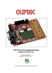
01
02 / 03
04
05 / 06
07 / 09
10
11 / 18
19 / 20
21 /22
23/36
37
38 / 45
46 / 47
TN-SW Intelligent Touch Panel Switch with Communication Function
TN-SW
Intelligent Touch Panel Switch with Communication Function
PACKAGE COMPONENTS
PACKAGE COMPONENTS
Reference Accessories
Reference Accessories
A
B
C
D
E
F
AAA
AAA
PRODUCT
Touch Panel cover plate
Switchgear driving box
User Manual
(Scene remote controller, require AAA battery X 2)
PRODUCT
SK-FACILITY-Remote
SAVEKEY
02
AG10/389A Button CellX2
Screw×2
03 SAVEKEY
TN-SW Intelligent Touch Panel Switch with Communication Function
INTRODUCTION
TN-SW series touch panel switches,accompanied with SK-Miniset-Remote controller, have
the function of light control correspondence, power-up scene and scene control. Remote scene
can be set by remote controller, simple design and easy operation. LED back light touch panel
design, the key can be seen even in dark with dim back light.
In case of power cut, EEPROM will keep the user setting still on the switch.
The product can work as standard wall switch, to be installed on BS4662 square wall box.
Terms
Description
· Light Control Key——the key to control device directly
· Scene Key——the key to control scene, not directly connected to device. Scene keys include
Master Key and Scene Key on touch panel.
· Scene——is a lighting situation in an area.
· Power-up Scene——work situation when the panel is electrified from power cut.
· Master On——touch on the Master Key (back light turn from dark to bright), activate a scene of
Master On.
· Master Off——Touch off the Master Key (back light turn from bright to dark), activate a scene
of Master Off.
· Touch Key Scene——the scene to be activated by touching on Scene Key on the touch panel.
· Remote Control Scene——the scene to be activated by remote controller.
· Light Control key Relation Setting——control a specific device by different keys in a BUS
Group.
TN-SW
Intelligent Touch Panel Switch with Communication Function
PRODUCT WIRING
2 way lighting circuit diagram
Light control circuit diagram
220AC
220AC
L1 COM L
1
C L2 L3 L4 L
Touch
Panel
2
N
Notice: Only the L1 can be used to connect in a 2 way lighting circuit.
Curtain control circuit diagram
220AC
Incandescent dimmer circuit diagram
220AC
open
C1
cl
ose open cl
ose
C2
D1 D2 L N
L N
M
N
04
1
N
M
SAVEKEY
Touch
Panel
N
05 SAVEKEY
TN-SW Intelligent Touch Panel Switch with Communication Function
PRODUCT WIRING
TN-SW
Intelligent Touch Panel Switch with Communication Function
PRODUCT INSTALLATION
1 Turn off main power supply of the circuit.
Networking diagram
NO
AB communication wire
AB communication wire
NO
NO
NO
OFF OFF OFF OFF
AB communication wire
NO
NO
NO
OFF OFF OFF
Notice: 1, AB wire must be STP (SHIELDED TWISTED PAIR) and connected as a BUS.
2, A wire is white, B wire is black, A must NOT be connected with B.
2 Open the cover plate of touch panel from switchgear driving box with screwdriver.
Networking 3D diagram
O p e n t he c o v e r f r a m e
AB communication wire
AB communication wire
AB communication wire
2 Open t h e t ouch p anel
Stp Standard: Rvvp 0.75x2
SAVEKEY
06
07 SAVEKEY
TN-SW Intelligent Touch Panel Switch with Communication Function
TN-SW
Intelligent Touch Panel Switch with Communication Function
PRODUCT INSTALLATION
PRODUCT INSTALLATION
3 Draw out strong electrical cable from wall box and trim them up,
press tightly on terminal block as illustration
5 Mount the switch driving section into wall box with 2 screws
and fix the touch panel and the cover frame
4 Connect the AB communication cables
SAVEKEY 8
6 Make setting as you like.
9 SAVEKEY
TN-SW Intelligent Touch Panel Switch with Communication Function
PRODUCT ID SETTING
TN-SW
Intelligent Touch Panel Switch with Communication Function
PRODUCT TYPE SETTING
User must set the ID for each touch panels before they are connected in a BUS group.
The jumper at the touch panel are for setting the ID. Each of the touch panels in a BUS group
must have a unique ID, not must NOT be the ID below. (NOTICE: Normally the ID for all the
touch panels are set differently before delivery. User doesn't have to change it by himself.)
Touch Panel
Step 1
Step 2
Step 3
Step 4
L1
L1
TN-SWL1
Touch the key as shown
on the picture
ON/OFF Switch
L1
L1
Push the buttons on the
Push the 'SET' button remote controller according
on the remote controller to the order in the picture
Push again the 'SET'
button on the remote
controller
Push the buttons on the
Push the 'SET' button remote controller according
on the remote controller to the order in the picture
Push again the 'SET'
button on the remote
controller
Push the buttons on the
Push the 'SET' button remote controller according
on the remote controller to the order in the picture
Push again the 'SET'
button on the remote
controller
Push the buttons on the
Push the 'SET' button remote controller according
on the remote controller to the order in the picture
Push again the 'SET'
button on the remote
controller
L2
L2
TN-SWL2
Touch the key as shown
on the picture
L1
L1
L2
L2
L3
L3
TN-SWL3
Touch the key as shown
on the picture
L2
L2
L1
L3
L1
L3
L4
L4
TN-SWL4
SAVEKEY
10
Touch the key as shown
on the picture
11 SAVEKEY
TN-SW Intelligent Touch Panel Switch with Communication Function
TN-SW
PRODUCT TYPE SETTING
Touch Panel
Step 1
Intelligent Touch Panel Switch with Communication Function
PRODUCT TYPE SETTING
Step 2
Step 3
Step 4
Touch Panel
Step 1
Step 2
Step 3
Step 4
Master
ON/OFF Switch
L1
L1
Push the buttons on the
Push the 'SET' button remote controller according
on the remote controller to the order in the picture
Push again the 'SET'
button on the remote
controller
L2
L2
TN-SWH2
Switch with Master Key
Touch the key as shown
on the picture
Push the buttons on the
Push the 'SET' button remote controller according
on the remote controller to the order in the picture
Push again the 'SET'
button on the remote
controller
OFF
Master
OFF
Master
OFF
TN-SWL1- M
12
L1
L1
Touch the key as shown
on the picture
Push the buttons on the
Push the 'SET' button remote controller according
on the remote controller to the order in the picture
Push again the 'SET'
button on the remote
controller
Push the buttons on the
Push the 'SET' button remote controller according
on the remote controller to the order in the picture
Push again the 'SET'
button on the remote
controller
Master
OFF
Push the buttons on the
Push the 'SET' button remote controller according
on the remote controller to the order in the picture
Push again the 'SET'
button on the remote
controller
Push the buttons on the
Push the 'SET' button remote controller according
on the remote controller to the order in the picture
Push again the 'SET'
button on the remote
controller
Push the buttons on the
Push the 'SET' button remote controller according
on the remote controller to the order in the picture
Push again the 'SET'
button on the remote
controller
L2
L3
L2
L3
TN-SWL3- M
L3
TN-SWM
Touch the key as shown
on the picture
L1
OFF
OFF
Push again the 'SET'
button on the remote
controller
L2
L1
Master
Master
Push the buttons on the
Push the 'SET' button remote controller according
on the remote controller to the order in the picture
L1
L1
TN-SWL2- M
OFF
Touch the key as shown
on the picture
OFF
L2
Master
Master
L1
L2
Touch the key as shown
on the picture
Master
OFF
L3
L1
L2
L4
L4
TN-SWL4- M
Switch with Scene Key
SAVEKEY
Touch the key as shown
on the picture
Switch with Master Key
TN-SWH1
OFF
Master
L1
L1
Touch the key as shown
on the picture
S1
S1
L1
S2
L1
S2
S3
S3
TN-SWL1S3
Touch the key as shown
on the picture
13 SAVEKEY
TN-SW Intelligent Touch Panel Switch with Communication Function
TN-SW
PRODUCT TYPE SETTING
Touch Panel
L1
L2
S1
L1
S2
L2
PRODUCT TYPE SETTING
Step 2
Step 3
Step 4
Touch Panel
Step 2
Step 3
Step 4
S1
S2
S1
S3
S1
Touch the key as shown
on the picture
L1
S1
L1
S1
L2
S2
L2
S2
L3
S3
L3
S3
TN-SWL3S3
Touch the key as shown
on the picture
L1
S1
L1
S1
L2
S2
L2
S2
L3
L4
L3
L4
Touch the key as shown
on the picture
Push the buttons on the
Push the 'SET' button remote controller according
on the remote controller to the order in the picture
Push the buttons on the
Push the 'SET' button remote controller according
on the remote controller to the order in the picture
Push the buttons on the
Push the 'SET' button remote controller according
on the remote controller to the order in the picture
Push again the 'SET'
button on the remote
controller
S2
S2
Push again the 'SET'
button on the remote
controller
Push again the 'SET'
button on the remote
controller
Switch witch All Scene Key
S1
TN-SWS2
Switch witch All Scene Key
Switch with Scene Key
TN-SWL2S3
TN-SWS1
Push again the 'SET'
button on the remote
controller
Push the buttons on the
Push the 'SET' button remote controller according
on the remote controller to the order in the picture
Push again the 'SET'
button on the remote
controller
S2
S3
Push the buttons on the
Push the 'SET' button remote controller according
on the remote controller to the order in the picture
Push again the 'SET'
button on the remote
controller
Push the buttons on the
Push the 'SET' button remote controller according
on the remote controller to the order in the picture
Push again the 'SET'
button on the remote
controller
Push the buttons on the
Push the 'SET' button remote controller according
on the remote controller to the order in the picture
Push again the 'SET'
button on the remote
controller
S3
Touch the key as shown
on the picture
S2
S2
S1
S1
S3
S4
S3
S4
TN-SWS4
S1
Push the buttons on the
Push the 'SET' button remote controller according
on the remote controller to the order in the picture
S1
S2
TN-SWS3
S4
Touch the key as shown
on the picture
Touch the key as shown
on the picture
S1
S1
14
Step 1
S3
TN-SWL4S2
SAVEKEY
Step 1
Intelligent Touch Panel Switch with Communication Function
Touch the key as shown
on the picture
S2
S1
S3
S4
S2
S3
S5
S5
TN-SWS5
Touch the key as shown
on the picture
15 SAVEKEY
TN-SW Intelligent Touch Panel Switch with Communication Function
TN-SW
PRODUCT TYPE SETTING
Step 1
S1
S2
S1
S2
S3
S4
S3
S4
S5
S6
S5
S6
TN-SWS6
Touch the key as shown
on the picture
PRODUCT TYPE SETTING
Step 2
Step 3
Push the buttons on the
Push the 'SET' button remote controller according
on the remote controller to the order in the picture
Step 4
Push again the 'SET'
button on the remote
controller
Switch with Master Key & Scene
Switch witch All Scene Key
Touch Panel
Intelligent Touch Panel Switch with Communication Function
Touch Panel
Step 1
Master
OFF
S1
Master
OFF
S1
L1
S2
L1
S2
L2
L3
L2
L3
TN-SWL3S2-M
Touch the key as shown
on the picture
Step 2
Step 3
Step 4
Push the buttons on the
Push the 'SET' button remote controller according
on the remote controller to the order in the picture
Push again the 'SET'
button on the remote
controller
Push the buttons on the
Push the 'SET' button remote controller according
on the remote controller to the order in the picture
Push again the 'SET'
button on the remote
controller
Push the buttons on the
Push the 'SET' button remote controller according
on the remote controller to the order in the picture
Push again the 'SET'
button on the remote
controller
Push the buttons on the
Push the 'SET' button remote controller according
on the remote controller to the order in the picture
Push again the 'SET'
button on the remote
controller
S1
S1
Switch with Master Key & Scene
Master
OFF
OFF
S2
L3
S3
L3
S3
Master
OFF
L1
S1
S2
Touch the key as shown
on the picture
Master
OFF
L1
S1
S2
S3
Touch the key as shown
on the picture
Master
S1
L1
L2
S2
OFF
16
Push again the 'SET'
button on the remote
controller
S3
TN-SWL1S3-M
Master
S1
L1
L2
S2
OFF
Push the buttons on the
Push the 'SET' button remote controller according
on the remote controller to the order in the picture
Push the buttons on the
Push the 'SET' button remote controller according
on the remote controller to the order in the picture
Push again the 'SET'
button on the remote
controller
S3
Dimmer & Curtain Switch
TN-SWS3-M
TN-SWD1
Touch the key as shown
on the picture
L3
L3
L4
L4
TN-SWD2
Touch the key as shown
on the picture
L3
L3
S3
TN-SWL2S3-M
SAVEKEY
Master
S2
Touch the key as shown
on the picture
Push the buttons on the
Push the 'SET' button remote controller according
on the remote controller to the order in the picture
Push again the 'SET'
button on the remote
controller
TN-SWDH1
Touch the key as shown
on the picture
17 SAVEKEY
TN-SW Intelligent Touch Panel Switch with Communication Function
TN-SW
PRODUCT TYPE SETTING
Touch Panel
Cur
t
ai
nCont
r
ol
TN-SWC1
Step 1
Touch the key as shown
on the picture
窗帘
窗帘
Intelligent Touch Panel Switch with Communication Function
PRODUCT FUNCTION & OPERATION
Step 2
Step 3
Step 4
Push the buttons on the
Push the 'SET' button remote controller according
on the remote controller to the order in the picture
Push again the 'SET'
button on the remote
controller
Push the buttons on the
Push the 'SET' button remote controller according
on the remote controller to the order in the picture
Push again the 'SET'
button on the remote
controller
Light Switch
Switch Key function: Touch on the switch key to turn ON/OFF the device.
Master Key function: Touch on the master key to control the Master ON/OFF scene.
Master Key turning off delay function: When the corresponding device is on, keep touching on the
master key for 3 seconds, the LED back light of it will sparkle, giving the user
enough time to leave the room or go to bed.
Scene Key function: Touch on the scene key to activate the scene.
窗纱
窗纱
See as below:
TN-SWC2
Touch the key as shown
on the picture
Notice: User can push the 'OFF' button on the remote controller to quit the setting at any step.
Master Key
Switch Key (L1)
Switch Key (L2)
SAVEKEY
18
MASTER
OFF
S1
Scene 1
L1
S2
Scene 2
L2
S3
Scene 3
19 SAVEKEY
TN-SW Intelligent Touch Panel Switch with Communication Function
PRODUCT FUNCTION & OPERATION
TN-SW
Intelligent Touch Panel Switch with Communication Function
PRODUCT FUNCTION & OPERATION
Dimmer touch panel
FACILITY-remote
Directly touch the panel to achieve brightness regulation. The corresponding LED
backlight on the touch panel will clearly indicate the on/off status of lamps.
Master on function: press MASTER ON key to achieve all “on” function of the touch panel. It is inapplicable
for curtain controller.
Master off function: press MASTER OFF key to achieve all “off” function of the touch panel. Curtain control
touch panel will stop the curtain's operation.
Corresponding keys control function: Four groups of device remote keys (Device 1, Device 2, Device 3, and
Device 4.) can be corresponding to the keys of touch panel after being set.
There is the same function you press the keys on remote or the keys on
touch panel.
Illustration
1 gang brighten-up key
2 gang brighten-up key
1 gang Dimmer
(D1 output control)
2 gang Dimmer (D2 output control)
1 gang dim-down key
2 gang dim-down key
Illustration of SK-FACILITY-Remote
Master Off key
Curtain control touch panel
Master On key
Open/close function: Directly touch the panel to open, close or stop curtain. The corresponding LED backlight
on the touch panel will clearly indicate the status of curtains.
Time-lapse stop function: The curtain will stop automatically with 1 minute time-lapse under opening status or
closing status.
Four group
of device
Remote key
Illustration
1 gang Curtain -open key
(C1-open output control)
2 gang C urtain open key
(C2-open output control)
1 gang Curtain stop key
2 gang Curtain stop key
1 gang Curtain close key
(C1-close output control)
C1
C2
2 gang Curtain close key
(C2-close output control)
SAVEKEY
Dimming control: Regulate the brightness through "+","-" key. "+" is to bright up; "-"is to dim down. The darkest is off.
Turn on/off control: Control device on/ off through"+","-"key."+"is to turn on; "-"key is to turn off.
Curtain control: Control curtain motor through "+","-" key. "+"key is to open curtain, "-"key is to close the curtain.
During the Process of motor operation, both "+" and "-" key are stop key.
Explanation: L Lamp Control; D Dimmer Control; C Curtain Control; M Master Control.
Notice: Key L, D, C can be set to work correspondingly in a BUS group.
SAVEKEY
20
21 SAVEKEY
TN-SW Intelligent Touch Panel Switch with Communication Function
REMOTE CONTROL FUNCTION & OPERATION
TN-SW
Intelligent Touch Panel Switch with Communication Function
PROGRAMME SETTING
Scene Remote Controller——Handy-remote
FACILITY-remote controller setting
The scene remote controller can control curtain, central air conditioning and background
acoustic system; and it can be set remote scene for a BUS group system.
The FACILITY-remote controller can control each of the lighting devices independently,
the way of setting is as below:
See as below: SK-Handy-Remote
Remote Scene
Master On
Illustration
Remote Scene Master Off
A
B
C
D
E
F
Remote Scene Key
1 Gang Curtain
Control Key
Open
Open
Stop
Stop
Close
Close
2 Gang Curtain
Control Key
SAVEKEY
Thermostat Control Key
Volume Up
Background Acoustic
System Master Key
Chanel Setting
Sound Source Switch
C1
C2
C1
C2
Volume Down
PRODUCT
Notice: Please refer to PROGRAMME SETTING to learn
the using and setting of this remote controller.
SAVEKEY
22
Sel
ecta l
i
ght
i
ng key
(
di
mmerkeyorcur
t
ai
n
st
op key) on t
ouch
panel
,keep t
ouchi
ng
on to
irf e
3con
s
ds.
Back i
gh
lt pa
s
r
kl
e
Sel
ect a gr
oup of devi
ce
control key on remote
cont
r
ol
l
er
,pr
ess'
+'t
o sett
he
cor
r
espondi
ngkey,pr
ess'
-'t
o
del
et
et
he cor
r
espondi
ng key
set
t
i
ng ec
r
or
d.
23 SAVEKEY
TN-SW Intelligent Touch Panel Switch with Communication Function
TN-SW
Intelligent Touch Panel Switch with Communication Function
PROGRAMME SETTING
PROGRAMME SETTING
Dimmer Power-Up Illumination Setting
Function Setting Key (Hidden) Instruction
Set the illumination for the dimmer in a BUS group once the BUS group is powering up.
Illustration
Illustration
4
Select a dimmer touch
panel, press the 'SET'
button on Miniset
remote controller.
SAVEKEY
24
When press 'SET' key on Miniset remote controller, the 6 hidden keys will be activated,
you can set the functions on the panel by the corresponding keys.
Touch panels sparkle
Press on the dimmer
setting key on Miniset
to set a specific
illumination of the
dimmer.
Power Up Scene
Setting Key
Light Control Relation
Setting Key
Master On Scene
Setting Key
Master Off Scene
Setting Key
Remote Scene
Setting Key
Touch Panel Scene
Setting Key
Press on the
'SET' key on
Miniset to finish
the setting.
25 SAVEKEY
TN-SW Intelligent Touch Panel Switch with Communication Function
TN-SW
Intelligent Touch Panel Switch with Communication Function
PROGRAMME SETTING
Light Control Key Relation Setting and Delete
·Light Control Key Relation Setting—Light control keys from the same or different panels work
together to control the same device.
·All the panels with light control key in the same BUS group can be used to set relation with other
light control keys from other panels.
Panel 1
Panel 2
Panel n
Relation
Setting
BUS
BUS
Setting process as below:
MASTER
OFF
Touch on the light control keys you need to set for relating.
(Once a key is chosen, bright back light is on)
Choose any touch panel,
push SET button on
Miniset controller
Touch on the UpperRight key (Relation
setting key)
All the Relation Setting
Keys in the BUS group
keep flashing
Panel 1
Panel 2
Panel n
Relating
Deleting
BUS
BUS
Activate a set of light control relation
SAVEKEY
26
Choose any touch panel,
push SET button on Miniset
controller to finish setting.
Choose any touch panel,
push DEL button on Miniset
controller to delete the set of
relation.
27 SAVEKEY
TN-SW Intelligent Touch Panel Switch with Communication Function
TN-SW
Intelligent Touch Panel Switch with Communication Function
PROGRAMME SETTING
Panel 1
Power-Up Scene Setting and Delete
·Power-Up Scene—Work situation when the panel is electrified from power cut.
·Any panel from a BUS group can be used to set power-up scene for all panels in the
same BUS group.
· Keys with flashing light are pending for choosing, keys with bright back light are
already chosen for turning on in the scene, while keys with dark back light are chosen
to be turned off in the scene.
Setting process as below:
S
S
S
Panel 1
S
S
S
Panel 2
Setting the
power-up
scene
Panel 2
BUS
Choose any touch
panel, push SET button
on Miniset controller to
finish setting.
BUS
MASTER
OFF
Panel n
Panel n
Choose any touch panel,
push SET button on
Miniset controller
BUS
BUS
Master
Touch on the Upper-Left
key (Power-Up scene
setting key)
Master
Touch on different light
control keys to change
the power-up scene
Activate the power-up
scene setting
SAVEKEY
28
Choose any touch
panel, push DEL button
on Miniset controller to
delete the power-up
scene.
Delete the power-up scene
29 SAVEKEY
TN-SW Intelligent Touch Panel Switch with Communication Function
TN-SW
Intelligent Touch Panel Switch with Communication Function
PROGRAMME SETTING
Panel 1
Master On/Off scene setting and delete
· Master On— Touch on the Master Key (back light turn from dark to bright), activate a
scene of master on.
· Master Off— Touch on the Master Key (back light turn from bright to dark), activate a
scene of master off.
·Only the touch panel with Master Key can be used to set Master On/Off scene.
·Keys with flashing light are pending for choosing, keys with bright back light are already
chosen for turning on in the scene, while keys with dark back light are chosen to be turned
off in the scene.
Set Master On
Setting process as below:
Master
Panel 1
Scene
Setting
Master
Panel 2
Panel 2
BUS
Choose any touch panel,
push SET button on
Miniset controller to
finish setting.
BUS
Panel n
MASTER
BUS
OFF
Panel n
Choose a panel with Master
Key, push SET button on
Miniset controller
S
S
S
Set Master Off
Touch on Left-Middle key for
setting Master On, or touch on
Right-Middle key for setting
Master Off.
SAVEKEY
30
BUS
Scene setting Activated
S
S
S
Touch on light control
keys on panels to change
the scene.
Choose any touch panel,
push DEL button on
Miniset controller to
delete the Scene.
Scene Delete
31 SAVEKEY
TN-SW Intelligent Touch Panel Switch with Communication Function
TN-SW
Intelligent Touch Panel Switch with Communication Function
PROGRAMME SETTING
Panel 1
Touch Key Scene Setting and Delete
· Touch Key Scene— the scene to be activated by touching on Scene Key on
touch panel.
· Only the touch panel with Scene Key can be used to set Touch Key Scene in
BUS group.
· In the process of Key Scene setting, keys with flashing light are pending
choosing; keys with bright back light are already chosen for turning on in
scene, while keys with dark back light are chosen to be turned off in the scene.
the
S
S
S
Panel 1
the
S
S
S
for
the
Setting process as below:
Panel 2
Touch Key
Scene Setting
Panel 2
BUS
6
BUS
PRODUCT
Choose any touch panel,
push SET button on
Miniset controller to
finish setting.
MASTER
OFF
S
Panel n
Panel n
Choose a panel with Scene
Key, push SET button on
Miniset controller
Touch on the bottom right
key on the touch panel
Touch on any Scene Key
on the chosen panel first,
then user can continue to
touch on any Scene Key in
the BUS group to set the
same scene for all the
Scene Key chosen.
BUS
BUS
Master
Choose any touch panel,
push DEL button on
Miniset controller to
Touch key Scene.
Master
Touch on light control keys
to change the scene.
Touch Key Scene
setting activated
Touch Key
Scene Delete
PRODUCT
SAVEKEY
32
33 SAVEKEY
TN-SW Intelligent Touch Panel Switch with Communication Function
TN-SW
Intelligent Touch Panel Switch with Communication Function
PROGRAMME SETTING
Panel 1
Remote Control Scene Setting and Delete
·Remote Control Scene—The scene to be activated by remote controller.
·All the panel in the BUS group can be used to start setting the remote control scene.
· In the process of Remote Control Scene setting, keys with
flashing light are pending for choosing; keys with bright back
light are already chosen for turning on in the scene, while keys
with dark back light are chosen to be turned off in the scene.
A
B
C
D
E
F
Setting process as below:
S
S
S
Panel 1
S
S
S
Panel 2
Remote Control
Scene Setting
BUS
Panel 2
6
BUS
PRODUCT
Choose any touch panel,
push SET button on
Miniset controller to
finish setting.
Push a scene
buttonon the
remote controller
MASTER
OFF
BUS
Panel n
PRODUCT
Panel n
BUS
Master
Choose any touch
panel, push DEL button
on Miniset controller to
Remote Control Scene.
Master
Choose any panel, push
SET button on Miniset
controller
Touch on the bottom left
key on the touch panel
Touch on light control
keys to change the scene.
PRODUCT
Remote control scene
setting activated.
Remote Control
Scene Delete
PRODUCT
SAVEKEY
34
35 SAVEKEY
TN-SW Intelligent Touch Panel Switch with Communication Function
TN-SW
Intelligent Touch Panel Switch with Communication Function
PRODUCT SPECIFICATIONS
PROGRAMME SETTING
Touch Panel All Setting Delete
·Delete all setting on touch panel, including scene setting, corresponding setting, dimmer
power up luminance and remote setting.
Memory Capacity
Current loading
Operate temperature
Operate humidity
SAVEKEY
36
Touch panel back
light sparkle.
Push 'SET' on
Miniset remote
controller, the
back light on touch
panel sparkle turn
around.
0%~95%
85~245VAC
rating frequency
50Hz/60Hz
Dimension
Keep touching on the
middle 2 keys for 3
seconds.
Refer to page 34~41
-10℃+50℃
rating voltage
fixed screw hole distance
PRODUCT
30 scenes、10 master off scenes、30corresponding groups
60.3mm(fit for BS4662 wall box)
86mmX86mmX46mm
PRODUCT
Push 'DEL' on
Miniset remote
controller to delete
all the setting.
37 SAVEKEY
TN-SW Intelligent Touch Panel Switch with Communication Function
TN-SW PRODUCT DESCRIPTION
Touch Panel
Load Type
Output
L1
Switch
TN-SWL2
TN-SWL3
100--240V
50/60Hz
4A X 2 gang
100--240V
50/60Hz
4A X 3 gang
L2
L1
L3
L4
TN-SWL4
SAVEKEY
38
100--240V
50/60Hz
4A X 4 gang
1. Touch-type on/off
control function;
2. LED backlight keys
indicate the status of
equipment
3. Perform scene driving
instruction(Refer to
Programming
Procedures setting)
4. Keys in a BUS group can
be controlled and work
correspondingly.(Progra
mme Setting)
TN-SWH1
L1
L2
Load Type
Output
Incandescent lamp,
fluorescent lamp,
12V spotlight with
transformer, 220V
spotlight, Energy
saving lamp and
other electronic
equipment requiring
power
100--240V
50/60Hz
4A X 3 gang
Incandescent lamp,
fluorescent lamp,
12V spotlight with
transformer, 220V
spotlight, Energy
saving lamp and
other electronic
equipment requiring
power
100--240V
50/60Hz
10A X 1 gang
100--240V
50/60Hz
4A X 4 gang
TN-SWH2
Switch with Master key
L1
L2
L3
Incandescent lamp,
fluorescent lamp,
12V spotlight with
transformer, 220V
spotlight, Energy
saving lamp and
other electronic
equipment requiring
power
Switch
L2
Touch Panel
Function Description
TN-SWL1
L1
Intelligent Touch Panel Switch with Communication Function
TN-SW PRODUCT DESCRIPTION
100--240V
50/60Hz
4A X 1 gang
L1
TN-SW
Master
OFF
TN-SW0M
Master
OFF
L1
Function Description
1. Touch-type on/off control
function;
2. LED backlight keys
indicate the status of
equipment
3. Perform scene driving
instruction(Refer to
Programming Procedures
setting)
4. Keys in a BUS group can
be controlled and work
correspondingly.(Progra
mme Setting)
Having Master Off scene,
user can turn off the device
at once but leaving some
other device turned on.
100--240V
50/60Hz
10A X 2 gang
TN-SWL1- M
39 SAVEKEY
TN-SW Intelligent Touch Panel Switch with Communication Function
TN-SW PRODUCT DESCRIPTION
Touch Panel
Load Type
TN-SW
TN-SW PRODUCT DESCRIPTION
Output
Touch Panel
Function Description
OFF
L1
L1
L1
Master
OFF
L2
L3
TN-SWL3- M
Master
OFF
L3
Incandescent lamp,
fluorescent lamp,
12V spotlight with
transformer, 220V
spotlight, Energy
saving lamp and
other electronic
equipment requiring
power
L1
100--240V
50/60Hz
4A X 3 gang
The Master key can
work on Master On
and Off scene, all
lighting key on
touch panels in the
BUS group can join
Master On/Off
scene.
100--240V
50/60Hz
4A X 4 gang
L2
L4
TN-SWL4- M
40
L1
S2
S3
TN-SWL1S3
L1
S1
L2
S2
L3
S3
TN-SWL3S3
L1
S1
L2
S2
L3
L4
Function Description
Incandescent lamp,
fluorescent lamp,
12V spotlight with
transformer, 220V
spotlight, Energy
saving lamp and
other electronic
equipment requiring
power
100--240V
50/60Hz
4A X3 gang
The Scene Key is to turn
on/off the scene set by
user, all lighting key on
touch panels in the BUS
group can join scenes.
100--240V
50/60Hz
4A X 4 gang
TN-SWL4S2
Incandescent lamp,
fluorescent lamp, 12V
spotlight with transformer,
220V spotlight, Energy
saving lamp and other
electronic equipment
requiring power
100--240V
50/60Hz
4A X 1 gang
The Scene Key is to turn
on/off the scene set by
user, all lighting key on
touch panels in the BUS
group can join scenes.
All Scene
Scene Switch
SAVEKEY
S1
S3
TN-SWL2S3
Output
100--240V
50/60Hz
4A X 2 gang
S2
L2
Scene Switch
Switch with Master key
TN-SWL2- M
100--240V
50/60Hz
4A X 2 gang
Load Type
S1
Master
L2
Intelligent Touch Panel Switch with Communication Function
S1
TN-SWS1
Connect with no device
The Scene Key is to turn
on/off the scene set by
user, all lighting key on
touch panels in the BUS
group can join scenes.
41 SAVEKEY
TN-SW Intelligent Touch Panel Switch with Communication Function
TN-SW PRODUCT DESCRIPTION
Touch Panel
Output
Touch Panel
Function Description
S2
TN-SWS2
S1
S2
S3
S4
S5
S6
Master
OFF
Connect with no device
S2
S3
S4
TN-SWS4
S2
S3
S5
TN-SWS5
SAVEKEY
42
The Scene Key is to turn
on/off the scene set by
user, all lighting key on
touch panels in the BUS
group can join scenes.
Function Description
The Scene Key is to turn
on/off the scene set by
user, all lighting key on
touch panels in the BUS
group can join scenes.
Connect with no device
S2
S3
Switch with Master & Scene Key
All Scene
S3
TN-SWS3
S1
Output
S1
S1
S4
Load Type
TN-SWS6
S2
S1
Intelligent Touch Panel Switch with Communication Function
TN-SW PRODUCT DESCRIPTION
All Scene
S1
Load Type
TN-SW
TN-SWS3-M
Master
OFF
L1
S1
S2
S3
TN-SWL1S3-M
Master
S1
L1
L2
S2
OFF
S3
Incandescent lamp,
fluorescent lamp,
12V spotlight with
transformer, 220V
spotlight, Energy
saving lamp and
other electronic
equipment requiring
power
100--240V
50/60Hz
4A X1 gang
Switch with Master
& Scene Key Function
100--240V
50/60Hz
4A X2 gang
TN-SWL2S3-M
43 SAVEKEY
TN-SW Intelligent Touch Panel Switch with Communication Function
TN-SW PRODUCT DESCRIPTION
Master
OFF
S1
L1
S2
L2
L3
TN-SWL3S2-M
Load Type
Incandescent lamp,
fluorescent lamp, 12V
spotlight with transformer,
220V spotlight, Energy
saving lamp and other
electronic equipment
requiring power
Output
100--240V
50/60Hz
4A X3 gang
Switch with Master
& Scene Key
Dimming Touch Panel
L4
Incandescent lamp
100--240V
50/60Hz
200W X2 gang
TN-SWD2
L3
Load Type
Output
100--240V
50/60Hz
4A X1 gang
1.Opening and closing the
curtain via controlling
forward and reverse
rotation of the motor
installed on the curtain
track
2.Changing scene while
100--240V
50/60Hz
4A X2 gang
scene control or master
scene signal received
TN-SWC1
forward and
reverse rotation
of AC motor
窗帘
窗纱
Function Description
TN-SWC2
TN-SWD1
L3
Touch Panel
Function Description
100--240V
50/60Hz
200W X1 gang
L3
Intelligent Touch Panel Switch with Communication Function
TN-SW PRODUCT DESCRIPTION
Curtain Controller
Switch with Master & Scene Key
Touch Panel
TN-SW
The Scene Key is to turn
on/off the scene set by
user, all lighting key on
touch panels in the BUS
group can join scenes.
100--240V
50/60Hz
400W X1 gang
TN-SW DH1
SAVEKEY
44
45 SAVEKEY
TN-SW Intelligent Touch Panel Switch with Communication Function
TROUBLE SHOOTING GUIDE
Symptom
Backlight of
touch panel
does not
illuminate
Solution
1. Wires are incorrect connected or
not properly secured.
Make sure that the input and output
wire is well connected with the
terminals, and the wiring is correct.
2. Master switch or leakage protection
switch is disconnected.
Connect the master switch and
leakage protection switch. If tripping
still occurs, please check whether
there is electrical leakage on the
equipment or whether the neutral
line of output phase is correct.
Connect the neutral line with correct
terminal.
1. The voltage is not stable, and the
power interference is strong.
Stop to use the equipment of big
interference and ask local
technicians to check.
2. Wiring is incorrect
Secure the connection and ensure
correct wiring.
3. The equipment or lamps are turned
off by the remote.
Confirm the control setting of remote
and the lamp control mode.
4.Controlled by scene key or
corresponding key on other touch
panels.
Confirm the setting of scene key and
corresponding key is correct.
Lamps can not
be turned off.
1.Load current exceeds the rated
operating current of the product.
Reduce the load power, and then
turn on the power. If the lamps still
can not work normally, please
change the driving part of the
product.
Touch panel
flashes
continuously.
1. Touch panel is damaged.
Replace the touch panel.
2. Touch panel is in the setting mode.
Exit the setting mode with Remote.
46
Intelligent Touch Panel Switch with Communication Function
TROUBLE SHOOTING GUIDE
3. Neutral line is not connected to the
equipment.
The controlled
equipment or
lamps turn off
automatically.
SAVEKEY
Possible Cause
TN-SW
Symptom
Possible Cause
Solution
Touch panel
cannot control the Incorrect wiring or connected with wrong
terminal.
correspondin
lamps.
Check whether the lamp wire is
connected to the output terminal
correctly and correspond to the certain
touch panel position.
Unable to
start setting
programme
on touch
panel
se an instrument to test if A and B wire
are connected correctly or short circuit
A and B communication wires are not
connected correctly, or short circuit
47 SAVEKEY