1
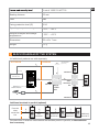
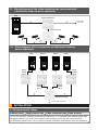
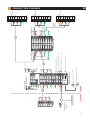
OUTDOOR
see ch. 5.3 Connection of
one external video camera
GREEN
BROWN
BLUE
ORANGE
BLUE
BROWN
ORANGE
GREEN
GREEN
BROWN
BLUE
ORANGE
INDOOR
(AWG 24)
UTP CAT 5e
(AWG 24)
UTP CAT 5e
+ACC
+14V
N
+14V
GNV
BUT
LC
LA/C
LA
GNV 1
GNV 2
Vin 2
Vcam
GND
GREEN
BROWN
BLUE
UTP CAT 5e
GREEN
or
(Optional)
GREEN
Not connected - with exterior camera
Auxiliary command (Optional)
AC Electromagnetic lock (Optional)
DC Electromagnetic lock
Door Opening Button (Optional)
(AWG 24)
BROWN
ORANGE
BROWN
BLUE
BLUE
ORANGE
ORANGE
Cable
2 x 0,5 mm
12V/7 Ah
ACC
Accumulator (Optional)
Connected- without exterior camera
.VDN.xxy
control unit
Supply
AUX 1
AUX 2
+Uv
Vout
Vin 1
GND
P
GND
CD IN CD OUT
-ACC
F
PROG
(Optional)
External video
camera
Panel
GNU
Vout
P
GND
CD
+14 V
Cable
3 x 0,75 mm
2x Sig. 10A
230 V AC/50Hz
Electrical panel
+14V
1+2
CD
1+2
GND
1+2
GND
1+2
+Uv
1+2
Vout
1
GNV
1
Vout
2
GNV
2
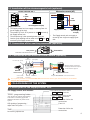
Video conection box
+14V
in-out
CD
in-out
GND
in-out
GND
in-out
+Uv
in-out
Vout
out
GNV
out
Vin
in
GNV
in
(AWG 24)
UTP CAT 5e
GREEN
GREEN
BROWN
BROWN
BLUE
BLUE
ORANGE
ORANGE
GREEN
BROWN
GREEN
BROWN
BLUE
ORANGE
(AWG 24)
UTP CAT 5e
(AWG 24)
UTP CAT 5e BLUE
ORANGE
GREEN
BROWN
BLUE
ORANGE
Terminal 2
Vout
GNV
Vin
+Uv
GND
CD
+14V
Dbl
Terminal 1
Vout
GNV
Vin
+Uv
GND
CD
+14V
Dbl
Terminal 3
Vout
GNV
Vin
+Uv
GND
CD
+14V
Dbl
Doorbell
Doorbell
Doorbell
5 CONNECTION DIAGRAM
EN
11