1
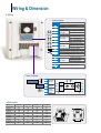
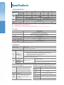
Specifications
Rated input/output
SV
055-2
7.5
5.5
9.1
24
iG5A[HP]
[kW]
[kVA] Note 2
[A] Note 3
Motor Note 1
Capacity
Current
Frequency
Voltage
[V]
[V]
Rated Voltage
input
Frequency
Cooling type
Weight
(kg)
Rated
output
Note 1 :
Note 2 :
Note 3 :
Note 4 :
Note 5 :
075-2
10
7.5
12.2
32
055-4
7.5
5.5
9.1
12
075-4
10
7.5
12.2
16
0~400 [Hz] Note 4
3Phases 200~230V
3Phases 380~460V Note 5
3Phases 200~230 VAC (+10%, -15%)
3Phases 380~460 VAC (+10%, -15%)
50~60 [Hz] ( 5%)
Forced cooling
3.86
4.01
3.86
4.01
Note 5
The motor capacities were indicated assuming to use 4 poles standard motors.
The rated input voltage for 200V is 220V and 400V is 440V.
Derating is needed when the carrier frequency is setup over 3kHz.
The maximum frequency can not be setup up to 300Hz in case of sensorless vector control.
The maximum output voltage does not rise over rated input voltage and the output voltage can be freely set up unless it exceeds the input voltage.
Control
Control type
V/F and sensloress vector
Digital : 0.01Hz
Analog : 0.06Hz (Maximum frequency:60Hz)
Digital operation : 0.01% of maximum output frequency
Analog operation : 0.1% of maximum output frequency
Linear, square, user V/F
150%/1Minute
Manual torque boost and auto torque boost
20% Note 1
150% with resistor Note 2
Frequency setup resolution
Frequency precision
V/F pattern
Overload capacity
Torque boost
Regenerative Maximum brake
braking torque Time/
Note 1 : 20% torque regenerative refers to the average braking torque of the motor loss which is generated at deceleration stopping.
Note 2 : Please refer to the user manual regarding the braking resistor specification.
Operation
Operation type
Frequency setup
Operation function
Input
P1~P8
Multi function
terminal (8points)
Output
Multi function open
collector terminal
Multifunction
relay terminal
Analog output
Selection among loader, terminal, communication, remote loader operations
Digital : Loader
Analog : 0~10V, -10~+10V, 0~20mA
PID control, up-down operation, 3-wire operation
NPN/ PNP selection
Function : Forward run, reverse run, emergency stop, fault reset, Jog, multi-step frequency-high, middle, low,
multi-step deceleration-high, middle,low, DC braking during stop, second motor selection,
frequency increase, frequency decrease, 3-wire run, external trip A/B,
changing run pattern from PID to normal operation mode
Changing run pattern from the option run to main operation mode, analog frequency fix,
Selecting during acceleration/decerelation stop
Outputs of the inverter faults
or running modes
Alarm
Instant
power
failure
Below 1 A (N.O, N.C) AC250V, Below 1A DC30V
0~10Vdc (Below 10mA) : Selection among frequency, current, voltage, DC voltage
Protective feature
Trip
Below DC 24V 50mA
Over voltage, low voltage, over current, ground
fault current detection, inverter over-heating,
motor over-heating, output overload protection,
communication error, output phase open, frequency
command loss, hardware fault, cooling fan fault
Stall prevention, overload
Below 15msec :
Runs without stopping yet both input voltage
and output should be within rated value
Over 15 Msec:
Automatic restart
Exterior structure and Environment
Protection
Ambient
temperature
Storage
temperature
Ambient
humidity
Altitude, vibration
Ambient
atmospheric pressure
Application site
Open type IP20
-10 ~50
-20 ~65
Below 90% RH (Non-condensing)
Below 1000M or 3,300FT . Below 5.9m/sec2 (0.6G)
70~106 kPa
No corrosive gas, combustible gas, oil mist or dust
Wiring & Dimension
Wiring
Control terminal
Terminal
Function
Multi function open-collector output
MO common
24V ouput /100mA
Multi function input FX : Forward run command
RX : Reverse run command
(initial setup)
Input signal common
BX : Emergency stop
Multi function input
JOG : Jog frequency run
(initial setup)
RST : Trip release signal
Input signal common
Multi step frequency-low
Multi function input
Multi step frequency-middle
(initial setup)
Multi step frequency-high
10V output terminal for the vloume resistor
Voltage signal input for frequency setup : -10~+10V
Current signal input for frequency setup : 0~20mA
Multi function analog output signal : 0~10V
A contact point output
B contact point output
Contact point common
Multi function
relay output
RS485 communication signal connection
Power Terminals
3Phases AC input
(Rated input voltage)
DB Resistor
Commercial
line input
DB resistor
connection
Motor
connection
Motor
Earth
Dimension
Inverter
Capacity [kW]
W [mm]
W1[mm]
H [mm]
H1 [mm]
D [mm]
[mm]
A [mm]
B [mm]
Weight [Kg]
SV055iG5A-2
5.5
180
170
220
210
170
4.5
5
4.5
3.86
SV075iG5A-2
7.5
180
170
220
210
170
4.5
5
4.5
4.01
SV055iG5A-4
5.5
180
170
220
210
170
4.5
5
4.5
3.86
SV075iG5A-4
7.5
180
170
220
210
170
4.5
5
4.5
4.01
W
W1
A
A
H1
H
D
B
W1
B