1
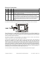
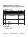
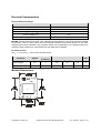
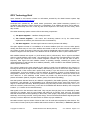
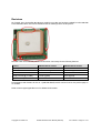
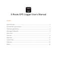
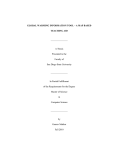
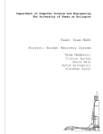
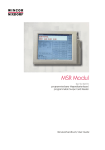
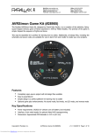
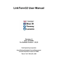
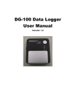
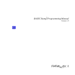
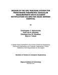
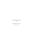
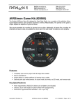
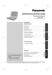
Web Site: www.parallax.com
Forums: forums.parallax.com
Sales: [email protected]
Technical: [email protected]
Office: (916) 624-8333
Fax: (916) 624-8003
Sales: (888) 512-1024
Tech Support: (888) 997-8267
Parallax GPS Receiver Module (#28146)
Designed in cooperation with Grand Idea Studio (www.grandideastudio.com), the Parallax Global
Positioning System (GPS) Receiver Module is a fully integrated, low-cost unit with on-board patch
antenna. Using the industry-standard SiRF StarIII chipset, the GPS Receiver Module is a complete GPS
solution in a very small footprint (1.93” x 1.42”). All design files, including the schematic and Parallax
SX/B firmware source code, are available from the Parallax GPS Module product page; search “28146” at
www.parallax.com.
The GPS Receiver Module provides standard, raw NMEA0183 (National Marine Electronics Association)
strings or specific user-requested data via the serial command interface, tracking of up to 20 satellites,
and WAAS/EGNOS (Wide Area Augmentation System/European Geostationary Navigation Overlay
Service) functionality for more accurate positioning results.
The Module provides current date, time, latitude, longitude, altitude, speed, and travel direction/heading,
among other data, and can be used in a wide variety of hobbyist and commercial applications, including
navigation, tracking systems, mapping, fleet management, auto-pilot, and robotics.
Features
Fully-integrated, low-cost GPS receiver with on-board, passive
patch antenna
Single-wire serial TTL interface to BASIC Stamp, Propeller, and
other microcontrollers
Provides raw NMEA0183 strings or specifically requested user
data via the command interface
Uses an industry-standard SIRF StarIII GPS chipset
0.1” pin spacing for easy prototyping and integration
Completely open-source with all design files available
Key Specifications
Power requirements: +5 VDC @ 65 mA (typical)
Communication: Asynchronous serial, 4800 bps @ TTL Level
Dimensions: 1.93 x 1.42 x 0.6 in (49 x 36 x 15 mm)
Operating temperature: 32 to 158 °F (0 to 70 ºC)
Revision Notification
If you purchased your GPS Module before March 2011 then you may have a V1.1 Module, which uses the
V1.1 documentation and firmware available on the product page of our website. For revision information
please see the last page of this document.
Copyright © Parallax Inc.
Parallax GPS Receiver Module (#28146)
v2.0 4/6/2011 Page 1 of 15
Electronic Connections
Pin
Name
Type
Function
1
GND
G
System ground. Connect to power supply’s ground (GND) terminal.
2
VCC
P
System power, +5V DC input.
Serial communication (commands sent TO the Module and data received
FROM the Module). Asynchronous, TTL-level interface, 4800 bps, 8 data bits,
no parity, 1 stop bit, non-inverted.
Mode select pin. Active LOW digital input. Internally pulled HIGH by default.
When the /RAW pin is unconnected, the default “Smart Mode” is enabled,
wherein commands for specific GPS data can be requested and the results will
4
/RAW
I
be returned (see the Communication Protocol section on page 4). When /RAW
is pulled LOW, the Module will enter “Raw Mode” and will transmit standard
NMEA0183 strings, allowing advanced users to use the raw information
directly.
Note: Type: I = Input, O = Output, P = Power, G = Ground:
3
SIO
I/O
The GPS Receiver Module can be integrated into any design using a minimum of three connections:
The on-board, four-pin, 0.1”-pitch header allows the GPS Receiver Module to easily be plugged into a
solderless breadboard or prototyping PCB. If the default “Smart Mode” is desired and the /RAW pin will
be unused, the Module can be simply connected to its host with a standard three-wire servo extension
cable (for example, Parallax #805-00001).
The Module is designed to mount horizontally, so the antenna can face to the sky. Screw holes are
located on each corner for more solid mounting if the user desires.
For best results, the Module should be used outdoors or with a clear view of the sky - this is the nature of
GPS and not a limitation of our product. With an unobstructed, clear view of the sky, GPS works
anywhere in the world, 24 hours a day, seven days a week. Please note that some products, such as
motors, computers, and wireless/RF devices, which emit high levels of magnetic field and interference,
may prevent the Module from receiving the required GPS signals from the satellites and may cause the
performance of the Module to decrease. Additionally, when using the Module in automobile applications,
the optimal position for the Module is mounted on the rooftop of the vehicle. If the Module is to be used
inside the car, ensure that the Module’s antenna still has a clear view of the sky, such as by placing it on
the dashboard, and is not blocked by any metal objects within the car.
For more information on GPS functionality, see the GPS Technology Brief section on page 6.
Copyright © Parallax Inc.
Parallax GPS Receiver Module (#28146)
v2.0 4/6/2011 Page 2 of 15
Status Indicators
The GPS Receiver Module contains a single red LED (light-emitting diode) to denote system status. The
LED is located in the lower-right corner of the Module. A white overlay on the Module’s PCB is used to
reflect the light from the LED, making it easier for the user to see. The LED denotes two states of the
Module:
1) Blinking (slow or fast): Searching for satellites or no satellite fix acquired
2) Solid: Satellites successfully acquired (a minimum of three satellites is required before the
Module will begin to transmit valid GPS data)
Upon powering the GPS Receiver Module in a new location, it may take up to five minutes for the Module
to retrieve the necessary almanac and ephemeris information from the satellites. During this time, the red
LED on the Module will blink. When the necessary information has been retrieved and enough satellites
are acquired in order for the Module to function properly, the red LED will turn and remain solid red.
If the LED is OFF, there may be a problem. Please check your wiring and configuration of the Module.
Mode Selection
The /RAW pin allows user selection of the GPS Receiver Module’s two operating modes:
Smart Mode: When the /RAW pin is pulled HIGH or left unconnected (the pin is internally pulled
HIGH), the default “Smart Mode” is enabled, wherein commands for specific GPS data can be
requested and the results will be returned. See the Communication Protocol section for more
details.
Raw Mode: When the /RAW pin is pulled LOW, “Raw Mode” is enabled in which the Module will
transmit standard NMEA0183 strings (GGA, GSV, GSA, and RMC), allowing advanced users to use
the raw information directly.
Copyright © Parallax Inc.
Parallax GPS Receiver Module (#28146)
v2.0 4/6/2011 Page 3 of 15
Communication Protocol (for use in “Smart Mode” only)
The GPS Receiver Module is controlled by the host via a standard TTL-level, asynchronous serial
communications interface. A single pin (SIO) transfers commands sent TO the Module and data received
FROM the Module. All communication is at 4800 bps, 8 data bits, no parity, 1 stop bit, non-inverted.
To send a command to the GPS Receiver Module, the user must send the ASCII header string of !GPS
followed by the specific hexadecimal command byte of their choice. Depending on the command, a
varying number of data bytes will be returned:
Description
Returned
Bytes
Cmd
Constant
Variables*
0x00
GetInfo
GPS Receiver Module version
2
Hardware, Firmware
0x01
GetValid
Check validity of data string
1
0 = Not Valid, 1 = Valid
0x02
GetSats
Number of acquired satellites
(20 maximum)
1
Satellites
0x03
GetTime
Time (UTC/Greenwich Mean Time)
3
Hours, Minutes, Seconds
0x04
GetDate
Date (UTC/Greenwich Mean Time)
3
Month, Day, Year
0x05
GetLat
Latitude
5
Degrees, Minutes,
Fractional Minutes (Word),
Direction (0 = N, 1 = S)
0x06
GetLong
Longitude
5
Degrees, Minutes,
Fractional Minutes (Word),
Direction (0 = E, 1 = W)
0x07
GetAltitude
Altitude above mean-sea-level
(in tenths of meters), 6553.5 m max
2
Altitude (Word)
0x08
GetSpeed
Speed (in tenths of knots),
999.9 knots max
2
Speed (Word)
0x09
GetHead
Heading/direction of travel (in tenths
of degrees)
2
Heading (Word)
0x0A
GetAltExt
Extended altitude mode. Altitude
above mean-sea-level (in meters),
65535 m max.
2
Altitude (Word)
*Variables are 1 byte each unless otherwise noted
Other Specifications
Navigation Update Rate of once per second (1Hz)
High signal sensitivity of -159 dBm
Position accuracy of +/- 5 meters
Velocity accuracy of +/- 0.1 meters per second
Copyright © Parallax Inc.
Parallax GPS Receiver Module (#28146)
v2.0 4/6/2011 Page 4 of 15
Electrical Characteristics
Absolute Maximum Ratings
Condition
Value
Operating Temperature
0ºC to +70ºC
Storage Temperature
-55ºC to +100ºC
Supply Voltage (VCC)
+4.5V to +5.5V
Ground Voltage (VSS)
0V
Voltage on any pin with respect to VSS
-0.6V to +(Vcc+0.6)V
NOTICE: Stresses above those listed under “Absolute Maximum Ratings” may cause permanent damage
to the device. This is a stress rating only and functional operation of the device at those or any other
conditions above those indicated in the operation listings of this specification is not implied. Exposure to
maximum rating conditions for extended periods may affect device reliability.
DC Characteristics
At VCC = +5.0V and TA = 25ºC unless otherwise noted
Specification
Symbol
Test
Conditions
Min.
Typ./Avg.
Max.
Supply Voltage
VCC
---
4.5
5.0
5.5
V
Supply Current, Active
ICC
---
---
65
---
mA
Parameter
Unit
Module Dimensions
Copyright © Parallax Inc.
Parallax GPS Receiver Module (#28146)
v2.0 4/6/2011 Page 5 of 15
GPS Technology Brief
Some material in this section is based on information provided by the Global Position System FAQ
(www.gpsy.com/gpsinfo/gps-faq.txt)
Developed and operated by the United States government, GPS (Global Positioning System) is a
worldwide radio-navigation system formed by a constellation of 24 satellites and their ground stations.
With an unobstructed, clear view of the sky, GPS works anywhere in the world, 24 hours a day, seven
days a week.
The Global Positioning System consists of three interacting components:
1) The Space Segment -- satellites orbiting the earth.
2) The Control Segment -- the control and monitoring stations run by the United States
Department of Defense (not discussed in this documentation).
3) The User Segment -- the GPS signal receivers owned by civilians and military.
The space segment consists of a constellation of 24 active satellites (and one or more in-orbit spares)
orbiting the earth every 12 hours. Four satellites are located in each of six orbits and will be visible from
any location on each 95 percent of the time. The orbits are distributed evenly around the earth, and are
inclined 55 degrees from the equator. The satellites orbit at an altitude of about 11,000 nautical miles.
Each satellite transmits two signals: L1 (1575.42 MHz) and L2 (1227.60 MHz). The L1 signal is modulated
with two pseudo-random noise signals - the protected (P) code, and the course/acquisition (C/A) code.
The L2 signal only carries the P code. Civilian navigation receivers only use the C/A code on the L1
frequency. Each signal from each satellite contains a repeating message, indicating the position and
orbital parameters of itself and the other satellites (almanac), a bill of health for the satellites (health bit),
and the precise atomic time.
The receiver measures the time required for the signal to travel from the satellite to the receiver, by
knowing the time that the signal left the satellite, and observing the time it receives the signal, based on
its internal clock. If the receiver had a perfect clock, exactly in sync with those on the satellites, three
measurements, from three satellites, would be sufficient to determine position in three dimensions via
triangulation. However, that is not the case, so a fourth satellite is needed to resolve the receiver clock
error. With four or more satellites, a GPS receiver can provide very accurate clock (time, date) and
position information (latitude, longitude, altitude, speed, travel direction/heading).
Note that position data and accuracy are affected or degraded by the satellite geometry, electromagnetic
interference, and multipath, an unpredictable set of reflections and/or direct waves each with its own
degree of attenuation and delay. Measuring altitude using GPS may introduce an accuracy error of 1.5
times the receiver’s position accuracy (in the case of the Parallax GPS Receiver Module, this corresponds
to about +/-7.5 meters in the vertical direction).
GPS signals work in the microwave radio band. They can pass through glass, but are absorbed by water
molecules (for example, wood or heavy foliage) and reflect off of concrete, steel, and rock. This means
that GPS modules have trouble operating in rain forests, urban jungles, deep canyons, inside automobiles
and boats, and in heavy snowfall - among other things. These environmental obstacles degrade positional
accuracy or make it difficult for the GPS module to achieve a proper satellite fix.
Most GPS receivers output a stream of data so that it can be used and interpreted by other devices. The
most common format (used by the Parallax GPS Receiver Module in “Raw Mode”) is NMEA0183 (National
Copyright © Parallax Inc.
Parallax GPS Receiver Module (#28146)
v2.0 4/6/2011 Page 6 of 15
Marine Electronics Association, www.nmea.org), developed for data communications between marine
instruments. Some receivers also have proprietary data formats used to transfer waypoint lists, track
logs, and other data between the GPS and a computer. Such proprietary formats are not covered by the
NMEA standard.
NMEA0183 is provided as a series of comma-delimited ASCII strings, each preceded with an identifying
header. Any microcontroller with a serial port can extract data from a GPS module. But, modules do not
produce "plain text" location information. Instead, they create standardized "sentences," such as:
$GPGGA,170834,4124.8963,N,08151.6838,W,1,05,1.5,280.2,M,-34.0,M,,,*75
$GPGSA,A,3,19,28,14,18,27,22,31,39,,,,,1.7,1.0,1.3*34
$GPGSV,3,2,11,14,25,170,00,16,57,208,39,18,67,296,40,19,40,246,00*74
$GPRMC,220516,A,5133.82,N,00042.24,W,173.8,231.8,130694,004.2,W*70
Programmers can then parse these strings to obtain their desired pieces of information, including time,
date, latitude, longitude, speed, and altitude. For more details on NMEA0183 sentence structure, visit:
http://home.mira.net/~gnb/gps/nmea.html
www.gpsinformation.org/dale/nmea.htm
The "Smart Mode” of the Parallax GPS Receiver Module will receive commands from the user and
automatically parse the necessary NMEA0183 strings to provide the requested information, as shown in
the output below, using the example code listing that begins on page 8:
Parallax GPS Receiver Demo
-------------------------Hardware Version: 1.0
Firmware Version: 2.0
Signal Valid: Yes
Acquired Satellites: 7
Local Time: 12:45:40
Local Date: 28 FEB 2010
Latitude:
Longitude:
Altitude:
Extended Altitude:
Speed:
Direction of Travel:
037° 46' 51.5" N ( 37.7809 )
122° 27' 50.8" W (-122.4641 )
45.3 meters
( 147 feet )
45 meters
( 147 feet )
28.5 Knots
( 32.7 MPH )
87.7°
There are three standard notations for displaying longitude and latitude data:
GPS Coordinates (degrees, minutes, and fractional minutes), ex: 36 degrees, 35.9159 minutes
DDMMSS (degrees, minutes, seconds), ex: 36 degrees, 35 minutes, 55.3 seconds
Decimal Degrees, ex: 36.5986 degrees
In “Smart Mode,” the Parallax GPS Receiver Module transmits latitude and longitude data to the user in
GPS Coordinate format (degrees, minutes, and fractional minutes). Conversion to the two other
notations, DDMMSS (degrees, minutes, second) and Decimal Degrees, is simple and demonstrated in the
example code that begins on page 8.
Copyright © Parallax Inc.
Parallax GPS Receiver Module (#28146)
v2.0 4/6/2011 Page 7 of 15
To graphically display your GPS position using Google Maps, go to http://maps.google.com/ and enter in
your decimal coordinates in the "Search" field (for example, "36.5986, -118.0599" without the quotes).
To graphically display a track or series of waypoints, GPS Visualizer (www.gpsvisualizer.com) is a free,
online utility that creates maps and profiles from GPS data. GPS Visualizer can read data files from many
different sources, including raw NMEA strings or tab-delimited or comma-separated text of relevant GPS
data.
Some additional resources and articles on GPS can be found here:
Where in the World is my BASIC Stamp?, Jon Williams, The Nuts and Volts of BASIC Stamps
(Volume 3; Column 83), under the Resources tab at www.parallax.com.
Stamping on Down the Road, Jon Williams, The Nuts and Volts of BASIC Stamps (Volume 4,
Column 103), under the Resources tab at www.parallax.com.
BASIC Stamp® 2 Program
The following code example demonstrates the GPS Receiver Module’s “Smart Mode” and displays the
number of acquired satellites, local time and date, latitude, longitude, altitude, extended altitude, speed,
and direction of travel.
This code is available for download from the Parallax GPS Module product page; search “28146” at
www.parallax.com.
' =========================================================================
'
'
File...... GPSDemoV2.0.B22
'
Purpose... Demonstrates features of the Parallax GPS Receiver Module
'
Author.... Joe Grand, Grand Idea Studio, Inc. [www.grandideastudio.com]
'
E-mail.... [email protected]
'
Updated... 03 MAR 2011
'
'
{$STAMP BS2}
'
{$PBASIC 2.5}
'
' =========================================================================
'
'
'
'
'
'
'
'
'
'
'
'
'
'
'
'
-----[ Program Description ]--------------------------------------------This program demonstrates the capabilities of the Parallax GPS Receiver
Module.
Before running this demo, ensure that the /RAW pin is left unconnected
or pulled HIGH to enable "smart" mode, in which the GPS Receiver Module
will accept commands and return the requested GPS data.
For an application that requires constant monitoring of multiple GPS
data components, it is recommended to use the "raw" mode of the GPS
Receiver Module by pulling the /RAW Pin LOW. In this mode, the module
will transmit a constant stream of raw NMEA0183 data strings, which can
then be parsed by the host application.
See the user manual for more details.
' -----[ I/O Definitions ]-------------------------------------------------
Copyright © Parallax Inc.
Parallax GPS Receiver Module (#28146)
v2.0 4/6/2011 Page 8 of 15
Sio
PIN
15
' connects to GPS Module SIO pin
' -----[ Constants ]------------------------------------------------------T4800
Open
CON
CON
188
$8000
Baud
CON
Open | T4800
MoveTo
ClrRt
FieldLen
CON
CON
CON
2
11
22
' DEBUG positioning command
' clear line right of cursor
' length of debug text
EST
CST
MST
PST
CON
CON
CON
CON
-5
-6
-7
-8
'
'
'
'
Eastern Standard Time
Central Standard Time
Mountain Standard Time
Pacific Standard Time
EDT
CDT
MDT
PDT
CON
CON
CON
CON
-4
-5
-6
-7
'
'
'
'
Eastern Daylight Time
Central Daylight Time
Mountain Daylight Time
Pacific Daylight Time
UTCfix
CON
PST
' set based on time zone location
DegSym
MinSym
SecSym
CON
CON
CON
176
39
34
' degrees symbol for report
' minutes symbol
' seconds symbol
' GPS Module Commands
GetInfo
CON
GetValid
CON
GetSats
CON
GetTime
CON
GetDate
CON
GetLat
CON
GetLong
CON
GetAlt
CON
GetSpeed
CON
GetHeading
CON
GetAltExt
CON
' Open mode to allow daisy chaining
$00
$01
$02
$03
$04
$05
$06
$07
$08
$09
$0A
' -----[ Variables ]------------------------------------------------------char
workVal
eeAddr
VAR
VAR
VAR
Byte
Word
workVal
ver_hw
ver_fw
VAR
VAR
Byte
Byte
valid
sats
VAR
VAR
Byte
Byte
' signal valid? 0 = not valid, 1 = valid
' number of satellites used in positioning calculations
tmHrs
tmMins
tmSecs
VAR
VAR
VAR
Byte
Byte
Byte
' time fields
day
month
year
VAR
VAR
VAR
Byte
Byte
Byte
' day of month, 1-31
' month, 1-12
' year, 00-99
Copyright © Parallax Inc.
' for numeric conversions
' pointer to EE data
Parallax GPS Receiver Module (#28146)
v2.0 4/6/2011 Page 9 of 15
degrees
minutes
minutesD
dir
W)
VAR
VAR
VAR
VAR
Byte
Byte
Word
Byte
'
'
'
'
latitude/longitude degrees
latitude/longitude minutes
latitude/longitude decimal minutes
direction (latitude: 0 = N, 1 = S, longitude: 0 = E, 1 =
heading
alt
altExt
supported
speed
VAR
WORD
' heading in 0.1 degrees
VAR
WORD
' altitude in 0.1 meters
VAR
WORD
' altitude in meters (no decimal, extended range,
in GPS firmware <= 2.0)
VAR
WORD
' speed in 0.1 knots
' -----[ EEPROM Data ]----------------------------------------------------NotValid
IsValid
DaysInMon
MonNames
DATA
DATA
DATA
DATA
DATA
"No", 0
"Yes", 0
31,28,31,30,31,30,31,31,30,31,30,31
"JAN",0,"FEB",0,"MAR",0,"APR",0,"MAY",0,"JUN",0
"JUL",0,"AUG",0,"SEP",0,"OCT",0,"NOV",0,"DEC",0
' -----[ Initialization ]-------------------------------------------------Initialize:
PAUSE 250 ' let DEBUG open
DEBUG CLS ' clear the screen
DEBUG MoveTo, 0, 1, "Parallax GPS Receiver Demo"
Draw_Data_Labels:
DEBUG MoveTo, 0,
DEBUG MoveTo, 0,
DEBUG MoveTo, 0,
DEBUG MoveTo, 0,
DEBUG MoveTo, 0,
DEBUG MoveTo, 0,
DEBUG MoveTo, 0,
DEBUG MoveTo, 0,
DEBUG MoveTo, 0,
DEBUG MoveTo, 0,
DEBUG MoveTo, 0,
DEBUG MoveTo, 0,
3,
4,
6,
7,
9,
10,
12,
13,
14,
15,
16,
17,
"
Hardware Version:
"
Firmware Version:
"
Signal Valid:
"Acquired Satellites:
"
Local Time:
"
Local Date:
"
Latitude:
"
Longitude:
"
Altitude:
" Extended Altitude:
"
Speed:
"Direction of Travel:
"
"
"
"
"
"
"
"
"
"
"
"
' -----[ Program Code ]---------------------------------------------------Main:
GOSUB Get_Info
GOSUB Get_Valid
GOSUB Get_Sats
GOSUB Get_TimeDate
GOSUB Get_Lat
GOSUB Get_Long
GOSUB Get_Alt
GOSUB Get_AltExt
GOSUB Get_Speed
GOSUB Get_Heading
GOTO Main
' -----[ Subroutines ]----------------------------------------------------Get_Info:
SEROUT Sio, Baud, ["!GPS", GetInfo]
Copyright © Parallax Inc.
Parallax GPS Receiver Module (#28146)
v2.0 4/6/2011 Page 10 of 15
SERIN Sio, Baud, 3000, No_Response, [ver_hw, ver_fw]
DEBUG MoveTo, FieldLen, 3, HEX ver_hw.HIGHNIB, ".", HEX ver_hw.LOWNIB
DEBUG MoveTo, FieldLen, 4, HEX ver_fw.HIGHNIB, ".", HEX ver_fw.LOWNIB
RETURN
' ---------------------------------------------------Get_Valid:
SEROUT Sio, Baud, ["!GPS", GetValid]
SERIN Sio, Baud, 3000, No_Response, [valid]
DEBUG MoveTo, FieldLen, 6
LOOKUP valid, [NotValid, IsValid], eeAddr
GOSUB Print_Z_String
DEBUG ClrRt
IF (valid = 0) THEN Signal_Not_Valid
RETURN
'
'
'
'
was the signal valid?
get answer from EE
print it
clear end of line
' ---------------------------------------------------Get_Sats:
SEROUT Sio, Baud, ["!GPS", GetSats]
SERIN Sio, Baud, 3000, No_Response, [sats]
DEBUG MoveTo, FieldLen, 7, DEC sats
RETURN
' ---------------------------------------------------Get_TimeDate:
SEROUT Sio, Baud, ["!GPS", GetTime]
SERIN Sio, Baud, 3000, No_Response, [tmHrs, tmMins, tmSecs]
SEROUT Sio, Baud, ["!GPS", GetDate]
SERIN Sio, Baud, 3000, No_Response, [day, month, year]
GOSUB Correct_Local_Time_Date
DEBUG MoveTo, FieldLen, 9, DEC2 tmHrs, ":", DEC2 tmMins, ":", DEC2 tmSecs
DEBUG MoveTo, FieldLen, 10, DEC2 day, " "
eeAddr = (month - 1) * 4 + MonNames
GOSUB Print_Z_String
DEBUG " 20", DEC2 year
RETURN
' get address of month name
' print it
' ---------------------------------------------------Get_Lat:
SEROUT Sio, Baud, ["!GPS", GetLat]
SERIN Sio, Baud, 3000, No_Response, [degrees, minutes, minutesD.HIGHBYTE,
minutesD.LOWBYTE, dir]
' convert decimal minutes to tenths of seconds
workVal = minutesD ** $0F5C ' minutesD * 0.06
DEBUG MoveTo, FieldLen, 12, DEC3 degrees, DegSym, " ", DEC2 minutes, MinSym, " "
DEBUG DEC2 (workVal / 10), ".", DEC1 (workVal // 10), SecSym, " "
DEBUG "N" + (dir * 5)
' convert to decimal format, too
workVal = (minutes * 1000 / 6) + (minutesD / 60)
DEBUG " (", " " + (dir * 13), DEC degrees, ".", DEC4 workVal, " )
RETURN
Copyright © Parallax Inc.
Parallax GPS Receiver Module (#28146)
"
v2.0 4/6/2011 Page 11 of 15
' ---------------------------------------------------Get_Long:
SEROUT Sio, Baud, ["!GPS", GetLong]
SERIN Sio, Baud, 3000, No_Response, [degrees, minutes, minutesD.HIGHBYTE,
minutesD.LOWBYTE, dir]
' convert decimal minutes to tenths of seconds
workVal = minutesD ** $0F5C ' minutesD * 0.06
DEBUG MoveTo, FieldLen, 13, DEC3 degrees, DegSym, " ", DEC2 minutes, MinSym, " "
DEBUG DEC2 (workVal / 10), ".", DEC1 (workVal // 10), SecSym, " "
DEBUG "E" + (dir * 18)
' convert to decimal format, too
workVal = (minutes * 1000 / 6) + (minutesD / 60)
DEBUG " (", " " + (dir * 13), DEC degrees, ".", DEC4 workVal, " ) "
RETURN
' ---------------------------------------------------Get_Alt:
SEROUT Sio, Baud, ["!GPS", GetAlt]
SERIN Sio, Baud, 3000, No_Response, [alt.HIGHBYTE, alt.LOWBYTE]
DEBUG MoveTo, FieldLen, 14, DEC (alt / 10), ".", DEC1 (alt // 10), " meters
workVal = alt / 10 ' remove tenths from altitude
' convert altitude from meters to feet
workVal = (workVal * 3) + (workVal ** $47E5) ' 1 meter = 3.2808399 feet
DEBUG " ( ", DEC workVal, " feet )
"
"
RETURN
' ---------------------------------------------------' The newer version of the Parallax GPS Receiver Module (firmware version >= 2.0)
using the PMB-648 supports an extended altitude command.
' See the user manual for more details.
Get_AltExt:
IF (ver_fw.HIGHNIB >= 2) THEN
SEROUT Sio, Baud, ["!GPS", GetAltExt]
SERIN Sio, Baud, 3000, No_Response, [altExt.HIGHBYTE, altExt.LOWBYTE]
DEBUG
MoveTo, FieldLen, 15, DEC altExt, " meters
"
' convert altitude from meters to feet
workVal = (altExt * 3) + (altExt ** $47E5) ' 1 meter = 3.2808399 feet
DEBUG " ( ", DEC workVal, " feet )
"
ELSE
DEBUG MoveTo, FieldLen, 15, "N/A"
ENDIF
RETURN
' ---------------------------------------------------Get_Speed:
SEROUT Sio, Baud, ["!GPS", GetSpeed]
SERIN Sio, Baud, 3000, No_Response, [speed.HIGHBYTE, speed.LOWBYTE]
DEBUG MoveTo, FieldLen, 16, DEC (speed / 10), ".", DEC1 (speed // 10), " Knots
"
' convert speed from knots to MPH
workVal = speed + (speed ** $2699) ' 1 knot = 1.1507771555 MPH
Copyright © Parallax Inc.
Parallax GPS Receiver Module (#28146)
v2.0 4/6/2011 Page 12 of 15
DEBUG " ( ", DEC (workVal / 10), ".", DEC1 (workVal // 10), " MPH )
RETURN
"
' ---------------------------------------------------Get_Heading:
SEROUT Sio, Baud, ["!GPS", GetHeading]
SERIN Sio, Baud, 3000, No_Response, [heading.HIGHBYTE, heading.LOWBYTE]
IF speed
DEBUG
ELSE
DEBUG
DegSym, "
ENDIF
RETURN
= 0 THEN
MoveTo, FieldLen, 17, "N/A
"
MoveTo, FieldLen, 17, DEC (heading / 10), ".", DEC1 (heading // 10),
"
' ---------------------------------------------------No_Response:
DEBUG MoveTo, 0, 18, "Error: No response from GPS Receiver"
PAUSE 5000
GOTO Initialize
'
' ---------------------------------------------------Signal_Not_Valid:
DEBUG MoveTo, FieldLen,
DEBUG MoveTo, FieldLen,
DEBUG MoveTo, FieldLen,
DEBUG MoveTo, FieldLen,
DEBUG MoveTo, FieldLen,
DEBUG MoveTo, FieldLen,
DEBUG MoveTo, FieldLen,
DEBUG MoveTo, FieldLen,
DEBUG MoveTo, FieldLen,
GOTO Main
7,
9,
10,
12,
13,
14,
15,
16,
17,
"?",
"?",
"?",
"?",
"?",
"?",
"?",
"?",
"?",
ClrRt ' clear all fields
ClrRt
ClrRt
ClrRt
ClrRt
ClrRt
ClrRt
ClrRt
ClrRt
' ---------------------------------------------------' Adjust date for local position
' Fixed by JZ for proper month adjustment in Location_Lags
Correct_Local_Time_Date:
workVal = tmHrs + UTCfix
IF (workVal < 24) THEN Adjust_Time
workVal = UTCfix
BRANCH workVal.BIT15, [Location_Leads, Location_Lags]
' add UTC offset
' midnight crossed?
' yes, so adjust date
Location_Leads:
day = day + 1
eeAddr = DaysInMon * (month - 1)
READ eeAddr, char
IF (day <= char) THEN Adjust_Time
month = month + 1
day = 1
IF (month < 13) THEN Adjust_Time
month = 1
year = year + 1 // 100
GOTO Adjust_Time
' east of Greenwich
' no, move to next day
' get days in month
Location_Lags:
day = day - 1
IF (day > 0) THEN Adjust_Time
' west of Greenwich
' adjust day
' same month?
Copyright © Parallax Inc.
Parallax GPS Receiver Module (#28146)
'
'
'
'
'
'
in same month?
no, move to next month
first day
in same year?
no, set to January
add one to year
v2.0 4/6/2011 Page 13 of 15
month = month - 1
IF (month > 0) THEN
eeAddr = DaysInMon + (month - 1)
month,
READ eeAddr, day
day
GOTO Adjust_Time
time.
ENDIF
month = 1
eeAddr = DaysInMon * (month - 1)
READ eeAddr, day
year = year + 99 // 100
' same year?
' same year, but different
' so need to adjust the
' before adjusting the
' no, set to January
' get new day
' set to previous year
Adjust_Time:
tmHrs = tmHrs + (24 + UTCfix) // 24
RETURN
' localize hours
' ---------------------------------------------------' Print Zero-terminated string stored in EEPROM
' -- eeAddr - starting character of string
Print_Z_String:
READ eeAddr, char
IF (char = 0) THEN Print_Z_String_Done
DEBUG char
eeAddr = eeAddr + 1
GOTO Print_Z_String
'
'
'
'
get char from EE
if zero, we're done
print the char
point to the next one
Print_Z_String_Done:
RETURN
' ----------------------------------------------------
Copyright © Parallax Inc.
Parallax GPS Receiver Module (#28146)
v2.0 4/6/2011 Page 14 of 15
Revisions
As of March 2011, the Parallax GPS Receiver module's core GPS unit has been updated from the PMB-248
to the PMB-648. Older units can be identified with the markings shown in this picture:
The older units are functionally identical to the newer ones except for the following features:
Feature
PMB-248 based module
PMB-648 based module
GPS chipset
Sony CXD2951GA-4
SiRF StarIII
Command set
GetAltExt not supported
GetAltExt supported
Maximum satellites tracked
12
20
Supply Current (@ +5 VDC)
115 mA (typical)
65 mA (typical)
Signal sensitivity
-152 dBm
-159 dBm
Documentation and firmware for the V1.1 (PMB-248-based) module can be found on the product page on
our website.
Please contact [email protected] for additional information.
Copyright © Parallax Inc.
Parallax GPS Receiver Module (#28146)
v2.0 4/6/2011 Page 15 of 15