1
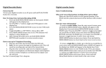
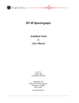
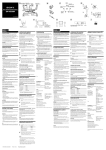
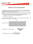
SIMPLIFIED OPERATION
MANUAL
Note
This manual introduces a simplified operating procedure of the
product so that even the person who uses it for the first time can
complete the operations.
For detailed operating procedures, refer to the separate Userʼs Manuals
[Safety] and [Hardware] as well as the Navigation/Online Help of the
software.
Retain this manual in an easily accessible place near the work desk
for future reference.
A X 7 9 2 3 [ TYPE 2 ]
Introduction
SAFETY PRECAUTIONS
Introduction
During observation and acquisition, the cover is kept closed to avoid
the risk on the user. However, when replacing the specimen holder, the
cover should be opened so care is required in this operation.
Also note that the laser beam is screened by a shutter and therefore
safe while the cover is opened.
Caution against high
temperature
(FV10i-W only)
This section becomes hot
for keeping the incubator
temperature.
Caution against finger
being caught
Main Controls
This section accommodates
motorized modules and the unit
should not be operated while the
cover is open.
Also be careful not to have your
hand or finger caught by the cover
when closing it.
Caution for specimen
replacement
Always remove the specimen
together with the specimen
holder.
Observation/Acquisition Flow
Observation Methods
2
Fluorescence observation
Phase contrast observation
T h i s m e t h o d u t i l i ze s t h e f l u o r e s c e n c e
generated when the specimen is irradiated
with strong light to observe the specimen
structure or identify the substance according
to the presence/absence and color tone of
the fluorescence.
This method makes it possible to observe a
non-stained specimen (living specimen) or
nearly transparent specimen, which is hard
to observe in brightfield observation, by
enhancing the contrast between brightness
and darkness.
Main Controls
Nomenclature
Incubator temperature
indicator (FV10i-W only)
Cover lock
buttons
Cover
Introduction
The indicator blinks during warm-up and light
steadily when the optimum temperature (34 to
38° C) is reached.
The temperature indicator shows “- - “ when the
heater is OFF.
(Provided on both sides)
Push and hold the bottoms
on the left and right sides to
open the cover.
FV10i-W main unit
(FV10C-W2)
STATUS LEDs
Sub switch
When both the main and sub switches are ON:
Left
LEDs
Right
Lighting
Lighting
Lighting
Lighting
Blinking
Software
Main switch
Power Supply Unit (FV10C-PSU)
: ON
Initializing
: OFF
Not run
Standby
Running
) and right LED (
blink when the cover is open.
Both the left LED (
The operations other than
those available with the
above controls can be
adjusted or set from the
software. (The operations are
easy using the Navigation.)
p. 11
)
Observation/Acquisition Flow
Blinking
Laser
Main Controls
FV10i-O main unit
(FV10C-O2)
3
This section describes the basic
operation flow in sequence together
with the monitor screen displays.
Observation/Acquisition Flow
Main Controls
Introduction
Observation/Acquisition Flow
System Setup
p. 6
4
Software
Setup
p. 8
Map Image
Acquisition
p. 10
CAUTION
Introduction
The description in this section assumes that the
following preparation work has been completed.
• The cables are connected properly.
• The tubes are connected. (FV10i-W only)
(For the connection methods, refer to the
separate User's Manual [Hardware].)
Main Controls
Observation/Acquisition Flow
Image Acquisition
p. 11
Image Editing/
Analysis
p. 13
System Termination
p. 14
5
Observation/Acquisition Flow
1. System Setup
Introduction
Starting the system
1
2
1
Set the main switch on the power
supply unit to “ I ” (ON).
2
Set the sub switch on the main unit to
turn it on.
Main Controls
To start up the main unit without
turning the heater ON, press and hold
the sub-switch until a short beep is
generated (for about 3 seconds).
3
Set the main switch of the display to
ON.
4
Open the front cover of the controller
and set the main switch to ON.
5
Log on Windows Vista with your own
user ID.
Observation/Acquisition Flow
4
If you have not yet registered your user
ID, log on with the factory default ID.
Factory default ID: fluoview
Password: fluoview
6
Installing the specimen holder
Push and hold the cover lock buttons
(on both sides), and lift the cover.
7
Install the specimen holder carrying
the specimen to be observed in the
main unit.
6
For details, refer to the User's Manual
[Hardware].
8
The software cannot be launched unless
the specimen holder is installed.
8
Push down the cover until it clicks to
indicate that it is closed.
Main Controls
7
Introduction
6
Observation is not available unless the
cover is closed completely.
Observation/Acquisition Flow
Stable images can be acquired if
acquisition is started after the following
warm-up period.
FV10i-W: 60 minutes
FV10i-O: 30 minutes
Now the system setup is complete.
7
Observation/Acquisition Flow
2. Software Setup
Introduction
Launching the software
1
).
) to steady
1
Double-click on the FV10i-SW icon
on the desktop to launch the software.
2
After the splash screen the logon
screen appears on the monitor screen.
Log on with your own user ID.
Main Controls
If you have not yet registered your user
ID, log on with the factory default ID.
Factory default ID: Administrator
Password: Administrator
3
Observation/Acquisition Flow
unit changes from blinking (
lighting (
2
8
Wait until the left STATUS LED on the main
3
The operation preparation screen
appears.
Checking water in the water feed nozzle (FV10i-W only)
2
Remove the specimen holder.
3
Press and hold the
botton. (It may sometimes take as
long as 30 seconds to 1 minute until
water comes out.)
4
When water comes out of the
water feed nozzle, release the
botton.
5
Install the specimen holder in the
original position.
6
Close the cover.
4
From the [Setup Dyes] list, select the
fluorescent dyes for use in observation
4
Main Controls
Open the cover.
Introduction
3
1
button.
and click on the
(Up to 4 dyes can be selected.)
5
Click on the
button.
Observation/Acquisition Flow
5
Now the software setup is complete.
9
Observation/Acquisition Flow
Main Controls
Introduction
3. Map Image Acquisition
The map image is the overall view of the specimen and used to locate the
observation target.
The description in this manual takes an example in which a fluorescence image is
selected and acquired as the map image.
Setting the map image acquisition condition
1
1
Select [Use Fluorescence].
2
When more than 3 kinds of fluorescent
dyes have been chosen, select the
combination of fluorescent dyes to be
used in the map image acquisition.
3
Click on the
4
Double-click on the position (container)
that you want to acquire the map
image.
5
Click on the
2
3
Acquiring the map image
Observation/Acquisition Flow
4
button.
button
to start the image acquisition.
6
5
When the map image is completed,
button.
click on the
6
Now the map image has been acquired.
10
4. Image Acquisition
Introduction
Selecting the acquisition mode
3
1
Click on the
button to select the
acquisition mode.
2
Double-click on the observation target
position (container) that you want to
acquire the image.
3
Click on the
view the Navigation.
Main Controls
2
1
button to
The following five acquisition modes are available.
Time Lapse: Sequential acquisition of the images of a specified area at
the specified time intervals.
Z Stack: Sequential acquisition of the images of a specified area by
varying the focused position at constant steps.
Observation/Acquisition Flow
Z Stack Time Lapse: Sequential acquisition combining the Z Stack and
Time Lapse modes.
Multi Area Time Lapse: Time Lapse acquisition while moving across
multiple specified areas.
Multi Area Z Stack Time Lapse: Z Stack/Time Lapse combined
acquisition while moving across multiple specified areas.
4
4
Hereafter, continue operation by
following the instructions given by
the Navigation.
When the operation is completed,
click on the
button to view
the next operated position and the
instruction on it.
11
Observation/Acquisition Flow
12
Se
lec
tin
gt
he
2.
S
co
ele
nta
tar cti
ine
ge ng
r
t p th
os e o
itio bs
erv
n
ati
3.
on
Pre
-sc
an
nin
g
4.
Fo
cu
sa
dju
stm
en
5.
t
Im
age
qu
alit
6.
ya
Z-a
dju
stm
set xis
ent
tin acq
g
uis
itio
na
rea
7.
Re
gis
ter
ing
the
co
8.
nd
Set
itio
ting
n
the
obs
erv
atio
9.
np
Set
erio
ting
d
the
dat
as
a
ve
10
con
.S
diti
tar
on
tin
ga
cq
uis
itio
n
1.
Main Controls
Introduction
Observation/Acquisition Flow
5. Flow of Image Acquisition
3
4
1
6
5
2
7
8
9
10
Time Lapse
Z Stack
Z Stack
Time Lapse
Multi Area
Time Lapse
Multi Area
Z Stack/
Time Lapse
Mandatory
As required
Unnecessary
6. Image Editing/Analysis
Switching to the Review Software
1
Click on the
button
on the toolbar to switch to the
Review software.
Introduction
1
The Review software
provides the following
functions.
Main Controls
• LUT modification
• Tile image display
• Maximum Intensity
Projection image
creation
• Annotation addition
• 3D image building
• Time lapse image file editing using Partial Open
• Stitch image creation using MATL Viewer
• File export
• Addition of user ID
The software also incorporates various other functions.
For details, open the [Help] menu and launch the Online Help.
Observation/Acquisition Flow
13
Observation/Acquisition Flow
7. System Termination
1
1
Click on the
button on the
Introduction
toolbar to exit the software.
Shut down Windows Vista.
3
Set the main switch of the display
to OFF.
4
Press and hold the sub switch on
the main unit for 3 seconds to turn
it off.
5
Set the main switch on the power
supply unit to “ ” (OFF) as
required.
Main Controls
4
2
Observation/Acquisition Flow
5
14
MEMO
Introduction
Main Controls
Observation/Acquisition Flow
15
Printed in Japan on February 00, 2010 M 000-01