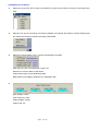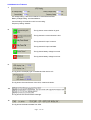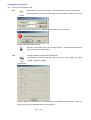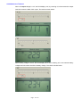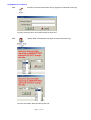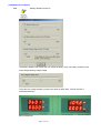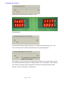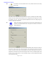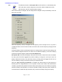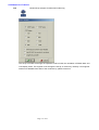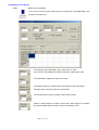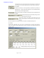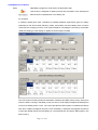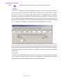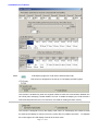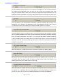
1
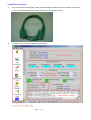
UPS Wizard User’s Manual
1.
The communication cable M2502: This is a special designed cable for the communication of UPS with
your PC; only connecting with the correct cable, the PC can detect the UPS.
2.
The main window of the UPS Wizard is shown below.
Page : 1 of 19
UPS Wizard User’s Manual
3.
Select the com port for UPS or select “Auto Detect” if you do not know which com port is connecting to the
UPS.
4.
When the com port is occupied by a monitoring software, for example, the UPSilon, the auto-detecting will
fail. Please exit UPSilon first before executing UPS Wizard.
5.
When the communication is O.K., it shows the following information.
UPS Type: On-Line, Line Interactive or OFF-Line.
Waveform: Pure Sine Wave or Step Wave.
Product Date Code: UPS manufacturing date.
Battery Date Code: Battery replacement or installation date.
6.
Input Voltage: 115Vac
Input Frequency: 60Hz
Output Voltage: 105Vac
Output Load: 0%
Page : 2 of 19
UPS Wizard User’s Manual
7.
AC Voltage Rating: 100/110/115/120Vac or 200/220/230/240Vac.
Battery Voltage Rating: 12/24/36/48/60/72…
Current Rating: UPS maximum O/P current rating.
Frequency Rating: 50/60Hz
8.
The fig shows communication is good.
The fig shows the communication is lost.
The fig shows AC input is normal.
The fig shows AC input has failed.
The fig shows battery voltage is normal.
The fig shows battery voltage is too low.
9.
The fig shows the display type is installed and the version of it.
The fig shows the manufacturer of the UPS, model and version.
10.
The fig shows the communication message.
11.
The fig shows the feed back data from UPS.
Page : 3 of 19
UPS Wizard User’s Manual
12.
Function icons for setting UPS.
12.1
Select the icon to input unlock code. The advanced functions are designed for
service engineer, you must input the unlock code to enable the advanced functions.
Please follow the key No (each for individual agent) to input correct pass code.
The fig shows pass code incorrect.
After input correct pass code. The unlock fig will show. All the advanced functions
(gray color icons) will be activated.
12.2
Analog to Digital converter (ADC) adjustment.
The function is used to adjust the ADC ratio for AC input voltage, AC output
voltage, and battery voltage.
The ADC provides ±7% adjustment. The result will be stored inside the flash memory of UPS so
that the set-up will not disappear when UPS is turned off.
Page : 4 of 19
UPS Wizard User’s Manual
When AC input voltage is 111V, but UPS shows 115V, by reducing 3% of the sensed AC input
level will correct the ADC of AC input. The result is shown below.
Page : 5 of 19
UPS Wizard User’s Manual
When AC output voltage is 111V, but UPS display 115V, by reducing 3% of the sensed AC output
level will correct the ADC of AC output. The result is shown below.
When battery voltage is 23.4V, but UPS display 22.9V, by increasing 2% of the sensed battery
voltage level will correct the ADC of battery voltage. The result is shown below.
Page : 6 of 19
UPS Wizard User’s Manual
12.3
Company name and model name set-up (support for advanced mode only)
Input the Company name and model name then press O.K.
12.4
Battery Date code adjustment (support for advanced mode only)
Input the new battery date code then press O.K.
Page : 7 of 19
UPS Wizard User’s Manual
12.5
Battery related level set-up.
The battery related levels include the O/P voltage at battery mode, low battery shutdown level,
and averaged floating charge voltage.
The actual O/P voltage at battery model is the same as rated value, 100/110/115/120 or
200/220/230/240Vac.
Before adjustment
Page : 8 of 19
UPS Wizard User’s Manual
Using the bar to adjust actual O/P voltage for ±3.5%.
After adjustment
The standard low battery shutdown level is 9.6V, it is allowed to adjust between 9.6V ~ 10.5V
when connecting the UPS with big external battery for long backup application.
When battery is not fully charged, the average charging voltage is 14V for each battery, to make
sure the battery being fully charged, the charging voltage 14V is not adjustable. When battery is
fully charged, the floating charging voltage will be reduced for extending the battery lifetime.
Normally, 13.5V for each battery is a suitable level.
Page : 9 of 19
UPS Wizard User’s Manual
12.6
The reduction of low AC transfer level is a very useful function when the utility
power is poor.
The lower the low AC transfer level, the lower the chance to discharge the battery energy.
However, the lower transfer level will decrease the O/P voltage level when utility power is normal
but voltage is very low.
Only those equipments applicable with wide I/P voltage range are
suitable for applying this adjustment.
12.7
When UPS reaches the full load level, the UPS will emit overload alarm and
shutdown at overload shutdown level. The higher the overload, the shorter the
battery backup time.
The Green mode function is to have UPS shut off automatically when load level is under the
preset level in battery mode. When a blackout happens, some equipment provides auto-shutdown
function, but some of them may not provide signal to shut down UPS because more than one
equipment is connected to the UPS, and the timing is hard to control. To enable the green mode
function will be a perfect solution to save the battery energy or provide shutdown/reset signal
when utility power is back.
Page : 10 of 19
UPS Wizard User’s Manual
To enable the function of Auto power ON, the UPS will turn on automatically from
12.8
OFF mode when connect utility power to the UPS; While if disable the function,
UPS will stay in the OFF mode but keep charging.
When the AC rating is changed, the O/P voltage will be changed not only at the battery mode, but
also at the AC mode.
When the frequency set-up is changed, the O/P frequency will not change at once, only after a
complete shutdown, and to have a DC start on the UPS; then, the O/P frequency will apply the set
frequency.
During the battery mode, by pushing the button for entering silence mode is a friendly design, but
when a blackout happens next time, the UPS won’t emit blackout beeping. To have the beeping
whenever a blackout happens, please enable Auto Buzzer ON.
Safe power ON is a function that delays “Auto power ON” function. When this function is enabled,
the Auto power ON will be triggered only after the battery is charged to 12.8V up for each 12V
battery. Without this function, any short time recovery of utility power will trigger the UPS to turn
ON, but if battery is empty, UPS cannot protect your equipment at all.
When the “High sensitivity for Blackout” is enabled, the UPS provides very fast response in
detecting the line voltage distortions, such as spikes, notches, dips, swells, and the distortions
caused by operation with generators as well. When power quality is poor, the UPS may frequently
transfer to battery mode operation, if a load can operate normally under poor power condition as
mentioned above, disable the High sensitivity may conserve the battery energy and capacity.
Page : 11 of 19
UPS Wizard User’s Manual
12.9
Model Set-up (support for advanced mode only)
The set-up of model will change the operation mode of UPS, the calculation of RS232 data, and
LCD display mode. The engineer must change the set-up of model very carefully. If an engineer
needs more detailed information of the model set-up, please contact us.
Page : 12 of 19
UPS Wizard User’s Manual
12.10
Backup time calculation
If you are not sure how much backup time you can get with a selected battery, this
program will answer you.
The capacity of the UPS battery 7Ah, 12Ah, 25Ah, or 38Ah…
If you use two 7Ah batteries in parallel connection; please input 14Ah.
The total battery voltage with series connection.
The transfer efficiency of UPS inverter from battery to the UPS output.
Generally, 85% is a typical value for UPS inverter.
The full load level of a UPS, change of each scale is 25W.
Under no load condition, the basic current that a UPS requires to maintain
the output voltage when the UPS is turned on at battery mode.
Page : 13 of 19
UPS Wizard User’s Manual
The high-density type provides higher depth of discharging as compared with
a normal type; so, it provides longer backup time when load is at high level.
For example:
The NP7-12 (YUASA) is a normal type battery, and REW45-12 (YUASA) is a
high density one. Both are the same capacity 7Ah-12V, but different backup
time when using in UPS at high load level.
Select ‘Auto Calculate’ to calculate the backup time when the parameters are
changed.
It shows the backup time when battery energy is 100%
discharged at full load level.
The full load current is the battery current when UPS is full
loaded. It helps engineer to decide what size of DC cable should
be used.
Fill in the information of the UPS; then press “calculate” to calculate the backup time.
For example:
A 2KVA model, 1200W UPS, uses 4 pcs of NP7-12 (YUASA) battery. The UPS inverter efficiency
is 85%, and it takes 0.8A from battery when no load is connected. The following fig shows the
calculation result.
Page : 14 of 19
UPS Wizard User’s Manual
New Battery (support for LCD version at advanced mode)
12.11
This function is designed for data input and auto-calculation of the backup time
after the UPS is replaced with a new battery set.
For example:
A 2.2KVA (1350W) UPS uses 4 REW45-12 (YUASA) batteries (high-density type) for battery
replacement. The UPS inverter efficiency is 88%, and it takes 0.6A from battery when no load is
connected, the charging current is 2.4A. Input the data for calculating the new set-up, and select
‘Write New Setting to UPS Setting’ to update the UPS backup time data.
The LCD version of UPS provides the estimation of backup time (EBT) with accuracy. Every time
when the UPS is running in the battery mode, the CPU of LCD display will adjust the backup time
record if low battery alarm occurs. The record provides the EBT system to calculate the backup
time when a blackout happens next time. Once the battery is replaced, the engineer will need to
re-input the related data of the new battery for a new backup time to keep the EBT system in the
best accuracy.
Page : 15 of 19
UPS Wizard User’s Manual
Battery Performance (support for LCD version at advanced mode)
12.12
The function is designed to adjust the database of backup time. When the battery performance
decays after years of using, the EBT system may not display the correct backup time. To check
the accuracy of EBT system, please select【Testing UPS to low battery】from the monitoring
software, for example, the UPSilon2000. When testing a UPS, the EBT will count down according
to the load level. When UPS emits low battery alarm, check LCD, if it shows 1 or 2minutes for the
backup time of the battery, it is very normal, basically, if total backup time is 20minutes, deviation
for 1 or 2minutes is acceptable, it’s suggested to make some adjustment if over 15%.
There are 8 kinds of battery performance records for the load level from 3% to 85%. Each time
when the UPS is running in the battery mode and discharged to low battery alarm, the backup
time will be recorded into the battery performance data for the reference of adjusting the battery
performance. Generally, we select the lower 3 or 4 values in average for the new set-up of battery
performance.
For example:
A UPS has 5 records of battery performance from 74% to 96%. We use the averaged value from
74% to 88% for calculation of decay. Input 81% for calculating the new backup time, and select
‘Write New Setting to UPS Setting’ to update the UPS backup time data.
Page : 16 of 19
UPS Wizard User’s Manual
12.13
LCD Display (support for LCD version at advanced mode)
This function is designed for the set-up of LCD display and EBT system.
This function is enabled only when the engineer needs to check the communication between the
two CPUs (main & display). Please disable it for user. If enable the beeping, the LCD will emit a
short-time beep whenever the LCD receives a command for reading the flash memory.
This function is designed to set up the display mode. When an LED-display UPS needs to install
an external LCD display for remote control, the control bus is in parallel connection. To separate
the control signal, the LCD display must be set in slave mode.
Page : 17 of 19
UPS Wizard User’s Manual
The UPS supports remote control for turn-on and turn-off schedule from the monitoring software,
for example, the UPSilon2000. User can check the set-up from the LCD display when UPS
receives a command from PC side. User can’t set, nor change the set-up at all without a PC. To
enable the function will provide a new way to change or set the time for turning on or off the UPS.
The LCD version of UPS will provide the estimation of backup time (EBT) with accuracy if the
database is correct. Engineer can disable this function if the database is wrong or when users do
not need this function. The following set-up will not run if EBT system is in off mode.
Normally, the EBT system is possible to show 1 or more minutes when UPS shutdown by battery
low. To adjust the database from the bar of【Adjust the battery performance for backup time after
decay】in ‘battery performance’, as shown in 12.12, may avoid this situation. Another simple way
is to turn off EBT system at low battery alarm; thus will force the UPS to count down the backup
time from 1.0 minute. However, the UPS may still have one more minute of backup time when the
countdown is 0.0 minute.
When this function is on, EBT will correct the count down in reference of battery voltage.
EBT system will record and adjust the backup time data under backup mode or test mode when
low battery alarm. The data is used for reference of EBT system under next blackout. The
following set-up will not run if EBT record is in off mode.
When this function is off, EBT will record and adjust the backup time data only at testing mode. If
an engineer can run【Testing UPS to low battery】from the monitoring software on schedule. This
function can set for off to prevent uncontrolled self-adjustment in backup time database.
Page : 18 of 19
UPS Wizard User’s Manual
There are 8 groups of database for different load levels. The adjustment method of the backup
time database can be changed separately according to the load condition. Normally, choose
‘exact value as tested’ is suggested.
When using the long life battery, the engineer may expect that the database will not change too
much each time when engineer run【Testing UPS to low battery】. This function can provide a way
to control self-adjustment in 5% to prevent wrong adjustment when UPS is not tested with fully
charged battery. Please select ‘Corrected value at ±5% maximum’ according to the load level that
UPS is loaded generally.
Page : 19 of 19