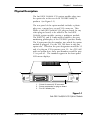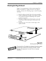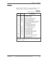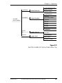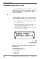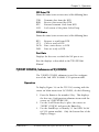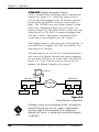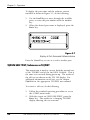
1
Nx56/64
(Second Generation)
Option Module PN 1202054L1
Plug-On Board PN 1202053L1
USER MANUAL
61202.054L1-1B
February 1996
901 Explorer Boulevard
P.O. Box 070020
Huntsville, AL 35807
Phone: (205) 971-8000
Fax: (205) 971-8699
© 1996 ADTRAN, Inc.
All rights reserved.
Printed in USA.
FEDERALCOMMUNICATIONSCOMMISSION
RADIOFREQUENCYINTERFERENCESTATEMENT
This equipment has been tested and found to comply with the limits for a Class A
digital device, pursuant to Part 15 of the FCC Rules. These limits are designed to
provide reasonable protection against harmful interference when the equipment is
operated in a commercial environment. This equipment generates, uses, and can
radiate radio frequency energy and, if not installed and used in accordance with the
instruction manual, may cause harmful interference to radio frequencies. Operation
of this equipment in a residential area is likely to cause harmful interference in which
case the user will be required to correct the interference at his own expense.
WARNING
Changes or modifications to this unit not expressly
approved by the party responsible or compliance could
void the user’s authority to operate the equipment.
Table of Contents
Table of Contents
Table of Contents
Chapter 1. Introduction
Second Generation (2nd GEN) Nx56/64 V.35 Option Module Overview .. 1
2nd GEN Nx56/64 V.35 Plug-On Board Overview .................................. 1
Functional Description of the 2nd GEN Nx56/64 V.35 Option Module
and Plug-On Board ..................................................................................... 2
Features of the 2nd GEN Nx56/64 Option Module ................................. 3
Interfaces .............................................................................................. 3
2nd GEN Nx56/64 (V.35) Option Module Specifications ................. 4
Physical Description .................................................................................... 5
Chapter 2. Installation
Unpack & Inspect ....................................................................................... 7
ADTRAN Shipments Include ...................................................................... 7
Customer Provides ...................................................................................... 7
Installing The Option Module .................................................................... 8
Placement of the Option Module ........................................................ 8
Power Connection ................................................................................ 8
Attaching the Plug-On Board ............................................................... 9
Warranty and Customer Service ............................................................... 10
Wiring ........................................................................................................ 11
Power-Up Testing and Initialization ......................................................... 12
Chapter 3. Operation
Overview .................................................................................................... 13
Front Panel Indicators/Buttons ................................................................ 13
Menu Structure .......................................................................................... 13
2nd GEN Nx56/64 V.35 Menus Are All Submenus ................................ 14
Operation ............................................................................................ 14
2)PORT Status, Submenu of 1)Status ...................................................... 16
Operation ............................................................................................ 16
7)PORT CONFIG, Submenu of 2)CONFIG ............................................ 17
Operation ............................................................................................ 17
3)FACTORY RESTORE, Submenu of 3)UTIL.......................................... 21
Operation ............................................................................................ 21
7)PORT UTILITY, Submenu of 3)UTIL ................................................... 21
Operation ............................................................................................ 21
2)RUN SELF TEST, Submenu of 4)TEST ................................................ 22
3)PORT TEST, Submenu of 4)TEST ........................................................ 23
Operation ............................................................................................ 23
61202.054L1-1
2nd GEN Nx56/64 Option Module User Manual
i
Table of Contents
Appendix A. TSU/HSU X00 System Messages
Alarm Messages ......................................................................................... 25
Network Interface (NI) ...................................................................... 25
2nd GEN Nx56/64 V.35 Option Module ......................................... 25
Status Messages ......................................................................................... 26
Network Interface (NI) ...................................................................... 26
2nd GEN Nx56/64 V.35 Option Module ......................................... 26
List of Figures
Figure 1-1 2nd GEN Nx56/64 V.35 Option Module ..................................... 5
Figure 2-1 Installing the Option Module ....................................................... 8
Figure 2-2 Attaching the Plug-on Board ......................................................... 9
Figure 3-1 TSU 100 Main Menu Tree ............................................................ 14
Figure 3-2 2nd GEN Nx56/64 V.35 Option Module Menu Tree ................ 15
Figure 3-3 Port Status Submenu ................................................................... 16
Figure 3-4 Port Configuration Submenu ...................................................... 18
Figure 3-5 Inband Remote Configuration .................................................... 20
Figure 3-6 Port Utility Submenu................................................................... 21
Figure 3-7 Display of Port Name and Software Version ............................... 22
Figure 3-8 Port Test Submenu ...................................................................... 23
List of Tables
Table 2-A V.35 Winchester Pin Connection. ............................................... 11
Table 3-A Normal Mode Operation (conditions which cause the
port control signal to be deactivated) ...................................... ...19
ii
2nd GEN Nx56/64 Option Module User Manual
61202.054L1-1
Chapter 1. Introduction
Chapter 1
Introduction
SECOND GENERATION (2ND GEN) NX56/64 V.35 OPTION
MODULE OVERVIEW
The Second Generation (2nd GEN) Nx56/64 V.35
option module is one of the option modules available for
use with the following ADTRAN equipment:
•
•
•
•
•
TSU 100 (part number 1200052L1)
TSU 600 (part number 1200076L1)
TSU 120 (part number 1200129L1)
HSU 100 (part number 1200097L1)
HSU 600 (part number 1200098L1)
The 2nd GEN Nx56/64 V.35 option module installs in
the option slot of the TSU/HSU family of products and
provides an additional synchronous V.35 interface port.
When used in these products, this interface port allows
an additional DTE to have access to the T1 service.
2ND GEN NX56/64 V.35 PLUG-ON BOARD OVERVIEW
The operations of the 2nd GEN Nx56/64 V.35 option
module described in this manual are also applicable for
the 2nd GEN Nx56/64 V.35 plug-on board. Operation
of both is identical except for the physical installation.
61202.054L1-1
2nd GEN Nx56/64 Option Module User Manual
1
Chapter 1. Introduction
THE FUNCTIONAL DESCRIPTION OF THE 2ND GEN NX56/
64 V.35 OPTION MODULE AND PLUG-ON BOARD
The 2nd GEN Nx56/64 V.35 option module operates in
the option slot of the TSU/HSU products while the plugon board operates as a plug-on to any option module.
Both are under the control of the TSU/HSU product.
The option module and the plug-on board are configured from the front panel or by an external PC program.
The internal menus for their configuration are part of
the option module and plug-on board and are automatically installed when either is plugged into a TSU/HSU
product.
2
2nd GEN Nx56/64 Option Module User Manual
61202.054L1-1
Chapter 1. Introduction
FEATURES OF THE 2ND GEN NX56/64 V.35 OPTION MODULE
•
Operates using 1 to 24 DS0s
•
Includes an elastic store for absorption of rate
variations
•
Capable of including a Nx56/64 V.35 plug-on
interface port, resulting in a dual port module
•
Outputs a 50 percent duty-cycle output clock at all
rates
•
Menu operation for easy configuration
•
Executes and responds to V.54 looping codes
•
Generates and checks a 511 test pattern
•
Performs an extensive self test
•
Supports multiport dial backup operation
•
Provides inband channel network management
communication
•
CCITT V.35 electrical (differential)
•
Connector
V.35 Winchester
•
Loopbacks
Port (toward the network)
DTE (toward the DTE)
Both loopbacks can be invoked locally or remotely
(V.54)
Interfaces
61202.054L1-1
2nd GEN Nx56/64 Option Module User Manual
3
Chapter 1. Introduction
2nd GEN Nx56/64 (V.35) Option Module Specifications
DTE Interface
CCITT V.35 Synchronous
Rates
56 kbps to 1.536 Mbps in 56K or 64K steps
Clock Options
Normal, Inverted
Tests
Local Loopback (Bilateral)
Menu activated
Remote Loopback (V.54)
Menu activated
Self Test
Test Pattern
511 with errored seconds display and error inject
capability
Data Inversion
Menu selectable
1s Density Protection
Force 1s to network after one second of consecutive
zeros from DTE. On/Off.
CTS, DCD, DSR Options
Normal or Forced ON
Connector
Winchester (V.35), female
Inband Communication Channel
Enabled, Disabled, or On-Demand
4
2nd GEN Nx56/64 Option Module User Manual
61202.054L1-1
Chapter 1. Introduction
Physical Description
The 2nd GEN Nx56/64 V.35 option module plugs into
the option slot in the rear of the TSU/HSU family of
products (see Figure 1-1).
The rear panel of the option module includes a plastic
plug over a cutout for a second V.35 connector. This
allows a 2nd GEN Nx56/64 V.35 plug-on board (or any
other plug-on board) to be added to the 2nd GEN
Nx56/64 option module creating a multiport module.
The PORT X.1 and X.2 indication is linked to the port
numbering philosophy of the TSU/HSU product family.
The X represents the slot number, into which the option
module is plugged. For the TSU 100 there is only one
option slot. Therefore the port designation would be 1.1
and, if a plug-on V.35 is present, port 1.2. In a TSU 600
with six option slots, these port numbers would be port
1.1 to port 6.1. The numbers appear in the front panel
LCD menu displays.
3
2
2
NX 56/64
PORT X.1
NX 56/64
PORT X.2
HOT
V.35
REPLACEABLE
V.35
1
1 - Cutout for second V.35 connector
2 - Screw receptacles for plug-on board
3 - Port X.2 header pins
Figure 1-1
2nd GEN Nx56/64 V.35 Option Module
61202.054L1-1
2nd GEN Nx56/64 Option Module User Manual
5
Chapter 1. Introduction
6
2nd GEN Nx56/64 Option Module User Manual
61202.054L1-1
Chapter 2. Installation
Chapter 2
Installation
UNPACK & INSPECT
Carefully inspect the option module or plug-on board
for any shipping damage. If damage is suspected, file a
claim immediately with the carrier and then contact
ADTRAN customer service. If possible, keep the original
shipping container for use in shipping the option
module or plug-on board back for repair or for verification of damage during shipment.
ADTRAN Shipments Include
•
•
The 2nd GEN Nx56/64 Module or
2nd GEN Nx56/64 Plug-on Board
The user manual (to be inserted into main
TSU/HSU user manual)
Customer Provides
•
61202.054L1-1
DTE cable
2nd GEN Nx56/64 Option Module User Manual
7
Chapter 2. Installation
INSTALLING THE OPTION MODULE
Placement of the Option Module
Figure 2-1 is representative of the action required for
proper placement of the option module. Perform the
following steps to install the option module:
1.
2.
3.
Remove the cover plate from the TSU/HSU unit rear
panel.
Slide the option module into the rear panel of the
TSU/HSU unit until it is positioned firmly against
the front of the unit.
Fasten the thumbscrews at both edges of the option
module.
Cover Plate
TSU/HSU
UNIT
Option Module
Figure 2-1
Installing the Option Module
Power Connection
Each option module derives power from the base TSU/
HSU unit. Power to the TSU/HSU is supplied by a
captive eight-foot power cord.
8
2nd GEN Nx56/64 Option Module User Manual
61202.054L1-1
Chapter 2. Installation
Attaching the Plug-On Board
Figure 2-2 is representative of the action required for
proper attachment of a plug-on board to the option
module. Perform the following steps to install the plugon board:
1.
2.
3.
4.
Hold the plug-on board above the option module.
Using a downward and right-to-left motion, slip the
V.35 Connector plug into opening in the option
module back panel.
Moving the plug-on board downward, secure the
connection of the header pins at the front of the
boards.
Install the two 4-40 screws at both edges of the
option module.
NX 56/64
PORT X.1
V.35
NX 56/64
PORT X.1
V.35
Figure 2-2
Attaching the Plug-On Board
The connection of the header pins between the option module
and the plug-on board must be visually verified. Severe
damage of the equipment can result from an improper
connection.
61202.054L1-1
2nd GEN Nx56/64 Option Module User Manual
9
Chapter 2. Installation
WARRANTY AND CUSTOMER SERVICE
ADTRAN will replace or repair this product within five
years from the date of shipment if it does not meet its
published specifications or fails while in service. For
detailed warranty, repair, and return information refer to
the ADTRAN Equipment Warranty, Repair, and Return
Policy Procedure.
Return Material Authorization (RMA) is required prior to
returning equipment to ADTRAN.
For Service, RMA requests, or more information, contact
one of the numbers listed at the end of this manual.
10
2nd GEN Nx56/64 Option Module User Manual
61202.054L1-1
Chapter 2. Installation
WIRING
The 2nd GEN Nx56/64 V.35 option module has a V.35
Winchester-style connection as defined in Table 2-A.
Table 2-A
V.35 Winchester Pin Connection
PIN
CCITT
DESCRIPTION
A
B
C
D
E
F
H
J
L
N
R
T
V
X
P
S
Y
AA
U
W
NN
101
102
105
106
107
109
104
104
115
115
103
103
114
114
113
113
-
Protective ground (PG)
Signal ground (SG)
Request to send (RTS) from DTE
Clear to send (CTS) to DTE
Data set ready (DSR) to DTE
Received line signal detector (DCD) to DTE
Data terminal ready (DTR) from DTE*
Ring indicator (RI)*
Local loopback (LL) from DTE*
Remote loopback (RL) from DTE*
Received data (RD-A) to DTE
Received data (RD-B) to DTE
RX clock (RC-A) to DTE
RX clock (RC-B) to DTE
Transmitted data (TD-A) from DTE
Transmitted data (TD-B) from DTE
TX clock (TC-A) to DTE
TX clock (TC-B) to DTE
External TX clock (ETC-A) from DTE
External TX clock (ETC-B) from DTE
Test mode (TM) to DTE
* Ignored by 2nd GEN Nx56/64 V.35 option module (firmware
revision F or higher).
61202.054L1-1
2nd GEN Nx56/64 Option Module User Manual
11
Chapter 2. Installation
Power-Up Testing and Initialization
The option module executes a self test during the
power-up sequence, as described in the TSU/HSU
manual. No initialization input is required. Upon
power-up, any previously configured setting for the
option module is automatically restored.
When the self testing is completed and the configuration
is successfully restored, the LED labeled OK in the
MODULE group on the front panel turns On. For more
information, see the section that discusses front panel
operation in the Operation chapter of the appropriate
TSU/HSU user manual. If any alarms are detected
during operation, the red LED labeled ALARM in the
MODULE group on the front panel turns On.
12
2nd GEN Nx56/64 Option Module User Manual
61202.054L1-1
Chapter 3. Operation
Chapter 3
Operation
OVERVIEW
The 2nd GEN Nx56/64 V.35 option module is controlled as part of the TSU/HSU using the same methods
as described in the appropriate TSU/HSU user manual.
Front Panel Indicators/Buttons
Refer to the description of the TSU/HSU front panel
indicators and buttons in the appropriate user manual.
Menu Structure
The 2nd GEN Nx56/64 V.35 option module menus
appear as a subset of, and operate the same as, menus
for the TSU/HSUs. The menus are accessed by selecting
1.1 2nd GEN Nx56/64 under the PORT menu items.
The Main menu for the TSU 100 is used for illustrative
purposes. The Main menu for the other TSU/HSU units
operates in a similar way. Figure 3-1 shows the TSU 100
Main menu with the PORT menu items printed in bold
italics.
See the figure TSU 100 Menu Tree in the TSU 100 User
Manual for a complete menu tree diagram.
61202.054L1-1
2nd GEN Nx56/64 Option Module User Manual
13
Chapter 3. Operation
1)NI PERF REPORTS
1)STATUS
2)CONFIG
TSU 100
MAIN MENU
2)NI ERRORS
1)NETWORK (NI)
3)ACTIVE ALARMS
2)UNIT
4)VIEW HISTORY
3)MAP XCHNG
5)PORT STATUS
4)MAP IN USE A (B)
5)DS0 MAP A
6)DS0 MAP B
7)PORT CONFIG
3)UTIL
1)ENTER PASSCODE
2)TIME/DATE
3)FACTORY RESTORE
4)REINIT UNIT
5)UNIT ID
4)TEST
1)NETWORK TESTS
6)SOFTWARE REV
2)RUN SELF TEST
7)PORT UTIL
3)PORT TEST
4)CANCEL TEST
Figure 3-1
TSU 100 Main Menu Tree
2nd GEN Nx56/64 V.35 Menus Are All Submenus
The 2nd GEN Nx56/64 V.35 option module menus are
accessed from and operated the same as menus for the
TSU 100. Menu items in the Main menu in Figure 3-1
printed in bold italics are submenu choices for 2nd GEN
Nx56/64 V.35 option modules (see Figure 3-2). Each
submenu is discussed in the following paragraphs. All
are accessed by the same method.
Operation
With the cursor on one of the four Main menu choices,
press the Enter or number key. The results are a display
of the first two submenu items with the cursor on the
first item. Use the Scroll Down key to place the cursor
on the desired item, then press Enter. This displays the
first two submenu choices
14
2nd GEN Nx56/64 Option Module User Manual
61202.054L1-1
Chapter 3. Operation
1)DTE DATA/CLOCK
1)STATUS
2)PORT STATUS
2)DTE STATUS
3)PORT RATE
1)INTERFACE
2)RATE
2)CONFIG
7)PORT CONFIG
2nd GEN
Nx56/64 MENU
3)TX CKL CNTRL
4)DATA
5)CTS
6)DCD
7)DSR
8)"0" INHIB
9)INBAND
3)UTIL
7)PORT UTILITY
SW REV
1)LOOPBACK
4)TEST
3)PORT TEST
2)511 PATT
3)DISP 511 RSLT
Figure 3-2
2nd GEN Nx56/64 V.35 Option Module Menu Tree
61202.054L1-1
2nd GEN Nx56/64 Option Module User Manual
15
Chapter 3. Operation
2)PORT Status, Submenu of 1)Status
The Status menu branch provides the ability to view the
status of the TSU 100 operation. It displays the status of
the monitored signal line on the 2nd GEN Nx56/64 V.35
option board and the data rate for which the option
module is configured.
Operation
To display Figure 3-3 on the TSU 100, starting with the
cursor on Main menu item 1)STATUS, do the following:
1.
2.
3.
Press the Enter or the number 1 key. This displays
the first two Status submenu items with the cursor
on 1)NI PERF RPTS.
Use the Scroll Down key to place the cursor on 5)
PORT STATUS and press the Enter key. This
displays the first available port.
Use the Scroll keys to identify 1.1 2nd GEN Nx56/
64 V.35 and press the Enter key.
Figure 3-3
Port Status Submenu
The Nx interface offers the status screens listed in this
manual. For other option modules, refer to the appropriate manual.
2ND GEN NX56/64 Status
Select 0.1 2ND GEN NX56/64
1) DTE DATA/CK
2) DTE STATUS
3) PORT RATE
16
2nd GEN Nx56/64 Option Module User Manual
61202.054L1-1
Chapter 3. Operation
DTE Data/CK
Shows the status (active or not active) of the following lines:
TXD
RXD
ETC
LCK
Transmit data from the DTE
Receive data toward the DTE
External transmit clock from DTE
Lock status of the phase locked loop
DTE Status
Shows the status (active or not active) of the following lines:
RTS
CTS
DCD
DSR
Request to send from DTE
Clear to send to DTE
Data carrier detect to DTE
Data set ready to DTE
Port Rate
Displays the data rate to which the NX port is set.
Exit the displays as described in the TSU 100 User
Manual.
7)PORT CONFIG, Submenu of 2)CONFIG
The 7)PORT CONFIG submenu is used for configuration of the 2nd GEN Nx56/64 V.35 option module.
Operation
To display Figure 3-4 on the TSU 100, starting with the
cursor on Main menu item 2)CONFIG, do the following:
1.
2.
3.
61202.054L1-1
Press the Enter or the number 2 key. This displays
the first two Configuration submenu items with the
cursor on 1)NETWORK (NI).
Use the Scroll Down key to place the cursor on
7)PORT CONFIG and press the Enter key.
Use the Scroll keys to identify 1.1 2nd GEN Nx56/
64 V.35 option module. Only the bottom line of the
display changes.
2nd GEN Nx56/64 Option Module User Manual
17
Chapter 3. Operation
Figure 3-4
Port Configuration Submenu
To select Port Configuration, press the Enter key. This
displays the first of eight submenu items. They are
defined as follows:
1)INTERFACE
This selects the active interface for the Base Nx port.
The Nx ports, which are installed as option modules,
have only one type of interface.
Choice - V.35
2)RATE 56/64
This sets the base rate of the interface. The actual data
rate depends on the number of DS0s assigned to the Nx
port. The DTE data rate versus the number of DS0s
appear in the appendix DTE Data Rate Chart of the TSU
100 User Manual.
Choices - 56K or 64K
3)TX CLK
Controls the clock used by the TSU 100 to accept the
transmit (TX) data from the DTE. Normally this is set to
Normal. If the interface cable is long, causing a phase
shift in the data, the clock can be selected as Inverted.
This switches the phase of the clock which should
compensate for a long cable.
Choices - Normal or Inverted
4)DATA
Used to control the inverting of the DTE data. This
inversion can be useful when operating with a high-level
data link control (HDLC) protocol (often used as a
means to ensure 1s density).
Choices - Normal or Invert
18
2nd GEN Nx56/64 Option Module User Manual
61202.054L1-1
Chapter 3. Operation
5)CTS
Used to control characteristics of CTS.
Choices - Normal or Force On (see Table 3-A).
6)DCD
Data Carrier Detect - Indicates to the DTE when a
valid signal is being received at the Network Interface.
Choices - Normal or Force On (see Table 3-A).
7)DSR
Data Set Ready - This signal indicates to the DTE when
the DCE is turned On and ready for operation.
Choices - Normal or Force On (see Table 3-A).
8)0 INHIB
If the Nx interface detects an uninterrupted string of 0s
being transmitted toward the network, and if 0s are
transmitted for more than one second, then the TSU 100
forces 1s towards the network.
Choices - On or Off
Table 3-A
Normal Mode Operation
(conditions which cause the port control signal to be deactivated)
SIGNAL
CTS
DCD
DSR
RTS
Follows
-
V.54
511 TEST SELF TEST NETWORK NO DS0 NETWORK
LOOPBACK
ON
ACTIVE TEST ACTIVE MAPPED ALARM
Off
Off
Off
Off
Off
Off
Off
Off
Off
Off
Off
Off
Off
Off
Off
-
- = Do not care
Force On = On under all conditions
61202.054L1-1
2nd GEN Nx56/64 Option Module User Manual
19
Chapter 3. Operation
9)INBAND (Inband Configuration Channel)
Used to enable/disable an 8 kbps remote configuration
channel (see Figure 3-5). When this option is set to
ON, the first DS0 mapped to the Nx interface operates
in 56K mode and the DTE clock rate is reduced by 8
kbps. The TSU/HSU uses this 8 kbps channel to send
and receive configuration data across a T1 span. As
shown in Figure 3-5, this allows the PC connected to the
chain-in port on TSU 600 A to monitor/configure both
TSU 600 A and B. This feature is useful when FDL
connectivity is not available across the T1 span.
This 8 kbps channel is only taken out of the first DS0. If
two 64K DS0s are mapped, the DTE rate would be 120
kbps instead of 128 kbps.
The menu option can also be set to On-Demand which
will activate the Inband Channel only when commands
are sent from T-Watch to the remote unit (TSU 600 B in
Figure 3-5). If no T-Watch activity is detected for 10
minutes, the Inband Channel is deactivated.
T-WATCH
TSU 600 B
TSU 600 A
CHAIN IN
NETWORK
NX
NX
DSX 1
ROUTER
PBX
DSX 1
ROUTER
PBX
Figure 3-5
Inband Remote Configuration
Although a router can accommodate this 8K rate reduction,
some DTE devices may not (i.e., video). Determination
should be made if the connected DTE can handle this
reduced clock source. A second option would be to operate
in 56K/DS0.
20
2nd GEN Nx56/64 Option Module User Manual
61202.054L1-1
Chapter 3. Operation
3)FACTORY RESTORE, Submenu of 3)UTIL
This selection is used to restore the factory default
settings for all Passthru option module parameters.
Operation
To return the unit to the opening Main menu with all the
factory default settings restored, do the following:
1.
2.
Follow the standard operating procedure to access
the 3)UTIL menu items.
With the cursor on 3)FACT RESTORE, press
the Enter key.
7)PORT UTILITY, Submenu of 3)UTIL
The 7)PORT UTILITY submenu is used primarily to
display the current software information for each port
installed in the unit. This information is required when
requesting assistance from ADTRAN Technical Support
or when updates are needed.
Operation
To display Figure 3-6 on the TSU 100, do the following:
1.
2.
Follow the standard operating procedure to access
the 3)UTIL menu items.
With the cursor on 7)PORT UTILITY, press
the Enter key. This displays the first available port.
Figure 3-6
Port Utility Submenu
61202.054L1-1
2nd GEN Nx56/64 Option Module User Manual
21
Chapter 3. Operation
To display the port name and the software version
installed as shown in Figure 3-7, do the following:
1.
2.
Use the Scroll keys to move through the available
ports, or enter the port number with the number
key.
When the desired port name is displayed, press the
Enter key.
Figure 3-7
Display of Port Name and Software Version
Press the Cancel key to exit or to select another port.
2)RUN SELF TEST, Submenu of 4)TEST
This menu item is used to execute both the internal test
of the TSU/HSU and of the 2nd GEN Nx56/64. This is
the same test executed during power-up. The results of
the self test are shown on the TSU 100 display. For
additional information on self test, see the chapter
Operation in the appropriate TSU/HSU user manual.
To activate a self test, do the following:
1.
2.
22
Follow the standard operating procedure to access
the 4)TEST menu items.
With the cursor on 2)RUN SELFTEST, press the
Enter key. This results in a changing TSU/HSU
display, showing the test outcome.
2nd GEN Nx56/64 Option Module User Manual
61202.054L1-1
Chapter 3. Operation
3)PORT TEST, Submenu of 4)TEST
This menu item is used to activate testing of specific
data ports. It also controls the activation of loopbacks
and the initiation of data test patterns. Test results are
shown on the TSU/HSU display.
The execution of Port Tests disrupts normal data flow in the
port being tested.
Operation
To display Figure 3-8 on the TSU 100, starting with the
cursor on 3)PORT TEST, press the Enter or number 3
key. This displays the available ports.
Figure 3-8
Port Test Submenu
1.1 2nd GEN Nx56/64: The Nx interface offers the
following test functions:
1) LOOPBK
Initiates a loopback.
PRT/LCL
REMOTE
OFF
61202.054L1-1
The Nx port activates both a local
loopback (back toward the DTE) and a
port loopback when either is invoked.
The remote loopback causes a V.54
code to be sent to the far end. The Nx
at the far end activates a PORT/LCL
loopback on detection of the V.54 code.
The loop is deactivated.
2nd GEN Nx56/64 Option Module User Manual
23
Chapter 3. Operation
The TSU/HSU checks the remote loopback activation by
detecting a proper response from the remote end. While
waiting for the response, the display shows LOOPING. If
successful, the display changes to LOOPED UP. If unsuccessful, the display shows FAILED.
2)511 PATT
Activates the generation of the 511 test pattern.
ON
OFF
The pattern check circuitry is enabled
and a test started. The test is ended by
selecting OFF.
The pattern generation and check is
disabled.
3)DIS 511 RESLT
Displays the results of the 511 test indicated in 2)511
PATT. The results are in the form of the number of
errored seconds. The error count can be cleared by
pressing the Clear key (Shift + 9). A bit error may be
inserted into the data stream by pressing the 2 key.
24
2nd GEN Nx56/64 Option Module User Manual
61202.054L1-1
Appendix A. TSU/HSU X00 System Messages
Appendix A
TSU/HSU X00 System Messages
ALARM MESSAGES
Network Interface (NI)
Red Alarm
NI unable to align frame with incoming signal
Yellow Alarm
Remote alarm indication (RAI) being received from the
far end
Blue Alarm
Unframed all 1s (AIS) being received at NI
Loss of Signal
No signal detected at NI
2nd GEN Nx56/64 V.35 Option Module
Clock Slip
Difference in frequency of the data clock at the network
and DTE
PLL Alarm
Unable to lock phase lock on the clock provided by the
network interface
Zeros Alarm
All 0s data being sent to the network interface
No EXT Clock
No external transmit clock at DTE (when applicable)
61202.054L1-1
2nd GEN Nx56/64 Option Module User Manual
25
Appendix A. TSU/HSU X00 System Messages
STATUS MESSAGES
Network Interface (NI)
Payload On
Payload loopback activated
Line On
Line loopback activated
Loopback Off
All loopbacks deactivated
Factory Restore
Factory setting restored
Power On
Unit powered on
Self Test
Internal self test performed
2nd GEN Nx56/64 V.35 Option Module
Loop Up
Data is looped back at both the network interface and
the DTE interface of the card
Remote Loop Up
Sending a V.54 pattern in an attempt to loop up a
remote device
511 Pattern On
Sending a 511 pattern towards the network interface
Loop Down
Data is no longer looped back at the network interface
or the DTE interface
511 Pattern Off
No longer sending a 511 pattern towards the network
interface
26
2nd GEN Nx56/64 Option Module User Manual
61202.054L1-1
Appendix A. TSU 100 System Messages
Product Support Information
Pre-Sales Inquiries and Applications Support
Please contact your local distributor, ADTRAN Applications Engineering, or ADTRAN Sales:
Applications Engineering
Sales
(800) 615-1176
(800) 827-0807
Post-Sale Support
Please contact your local distributor first. If your local
distributor cannot help, please contact ADTRAN Technical Support and have the unit serial number available.
Technical Support
(800) 726-8663
Repair and Return
If ADTRAN Technical Support determines that a repair is
needed, Technical Support will coordinate with the
Return Material Authorization (RMA) department to
issue an RMA number. For information regarding
equipment currently in house or possible fees associated
with repair, contact RMA directly at the following
number:
RMA Department
(205) 971-8722
Identify the RMA number clearly on the package (below
address), and return to the following address:
ADTRAN, Inc.
RMA Department
901 Explorer Boulevard
Huntsville, Alabama 35806-2807
RMA # _____________
61202.054L1-1
Nx56/64 Option Module User Guide
27
Appendix A. TSU 100 System Mesaages
28
Nx56/64 Option Module User Manual
61202.054L1-1