1
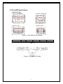
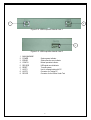
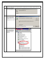
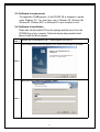
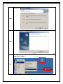
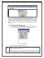
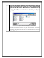
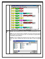
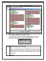
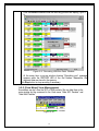
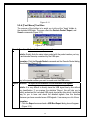
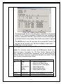
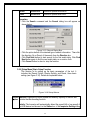
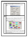
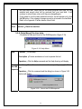
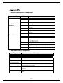
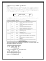
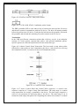
Edition 1.0 Feb. 22, 2005 EZ-USB-168 User manual 1 FCC COMPLIANCE STATEMENT FOR AMERICAN USERS This equipment has been tested and found to comply with the limits for a CLASS A digital device, pursuant to Part 15 of the FCC Rules. These limits are designed to provide reasonable protection against harmful interference when the equipment is operated in a commercial environment. This equipment generates, uses, and can radiate radio frequency energy and, if not installed and used in accordance with the instructions, may cause harmful interference to radio communications. Operation of this equipment in a residential area is likely to cause harmful interference in which case the user will be required to correct the interference at his own expense. EMS AND EMI COMPLIANCE STATEMENT FOR EUROPEAN USERS This equipment has been tested and meet the requirements relating to electromagnetic compatibility based on the standards EN50081-1 (EN55022 CLASS A) and EN61000-4-2/-3/-4/-5/-6/-8/-11 (IEC Teil 2,3,4). The equipment has also been tested and is verified to be within the European Standard EN55022 for the both Radiated and Conducted emissions limits. Specifications are subject to change without notice. 2 EMS AND EMI COMPLIANCE STATEMENT..................................................2 FOR EUROPEAN USERS ............................................................................2 Chapter 1 The USB Inspector ........................................................................................4 1-1 introduction......................................................................................................4 1-2 The equipments................................................................................................5 1-3 Specification ....................................................................................................5 1-4 The USB specification.....................................................................................6 Chapter 2 Installation.....................................................................................................7 2-1 Hardware requirement .....................................................................................7 2-2 Hardware installation.......................................................................................7 2-3 Software’s requirement..................................................................................11 2-4 Software’s Installation...................................................................................11 Chapter 3 Getting Started with the Inspector...............................................................13 3-1 Introduction ...................................................................................................13 3-2 Starting with EUSBinspector.........................................................................13 3-2-1 [File] file management .......................................................................15 3-2-2 [View] the view management ............................................................19 3-2-3 [Capture] Recording function.............................................................18 3-2-4 [Tool] Tool box ..................................................................................19 3-2-5 [Setup] Basic setup function ..............................................................22 3-2-6 [Help] On line help.............................................................................24 Appendix......................................................................................................................25 1 Appendix one ....................................................................................................25 2 Appendix two....................................................................................................25 3 Appendix three..................................................................................................26 3 Chapter 1 The USB Inspector 1-1 introduction The EZ-USB-168, which is also called as “USB Inspector”, is a debugging tool used for intercepting on-line USB signal of any USB 1.1 compliant device by inserting it between the host and USB device through two USB cables. The tool can extract the USB protocol without interrupting the operation, that is, when the USB device is operating with the host PC. After properly decoding the filtered-out USB signal from the USB cables, the EZUSB-168 Inspector transfers the signal to the same or another PC by using another USB port. When the driver program in the PC receives the coded data from the Inspector, it will display the data on the monitor for you to analyze and debug. The major features of the EZ-USB-168 are as shown below: Complies with the USB1.1 Full Speed & Low Speed specification. Auto–detects Full Speed & Low Speed。 512K X 8 bits SRAM included。 Uses USB1.1 port to communicate with the host PC and does not need extra power to operate. Compact size, easy to carry, and saves space. Easy installation and usage. 4 1-2 What You Should Get? The standard shipment of the EZ-USB-168 Inspector should consist of the following components packed in a box: A main frame. Two USB cables (1M and 1.8M). A compact disk containing the driver, application and user manual. A warranty. 1-3 Specification Package Size Weight Socket 1(HOST1) Socket 2(HOST2) Socket 3(DEVICE) Cable 1 Cable 2 L X W X H = 14.60cmX9.60cmX2.50cm 325g USB 1.1“B” Receptacle USB 1.1 “B” Receptacle Note 1 USB 1.1 “A” Receptacle Note 1 1.0M USB 1.1 ( “A” Plug + “B” Plug) cable 1.8M USB 1.1 ( “A” Plug + “B” Plug) cable 4.75V~5.25V VBUS Current Consumption 90 mA Power (Normal) Current Consumption 100mA (Record) Record Memory SRAM 512K X 8 bits Size Reset System Switch Reset Lights up when inspector is powered on POWER Lights up when inspector cannot be initialized ERROR correctly LED Lights up when inspector is normally configured CONFIG Lights up when inspector is recording USB signal RECORD Socket1 Transmission USB 1.1 Full speed Control and Bulk mode Mode Transfer Mode Socket2 & Socket3 Any one of the USB 1.1 transfer mode Transmission Mode 5°C to 40°C Operating Range Operation 0°C to 80°C Environment Storage Range 10% to 90% Humidity CE, FCC Class A Certification Product Elan offers one-year limited warranty Warranty Table 1-1 Note1: Please see “section 1-4 the USB specification” to rightly choose the cable. 5 1-4 The USB Specification Connector type TYPE A-> Receptacles TYPE B-> Receptacles TYPE A-> Plug TYPE B-> Plug Figure 1-1:EZ-USB-168 Connectors Contact Number Signal Name 1 VBUS 2 D- 3 D+ Table 1-2 Figure 1-2:EZ-USB-168 Cable 6 4 GND Shell Shield Chapter 2 Installation 2-1 Hardware’s Requirement IBM PC Pentium IV Speed 650Mhz 128M bytes RAM Two USB 1.1 ports A 1024X768 monitor A CD ROM 2-2 Hardware’s Installation Figure 2-1,2-2,2-3 show USB Inspector outlook from different view. 1 2 3 4 5 6 Figure 2-1: USB Inspector vertical view 7 7 8 Figure 2-2: USB Inspector lateral view 1 9 Figure 2-3: USB Inspector lateral view 2 1. 2. 3. 4. 5. 6. 7. 8. 9. MAIN MACHINE POWER ERROR CONFIG RECORD RESET HOST1 HOST2 DEVICE System power indicator System function error indicator Normal operation indicator USB signal record indicator To reset system Use for communication with PC Connector for Testing PC Connector for the Device Under Test 8 STEP1 Turn on PC and wait for the Windows OS to be ready. Connect the USB cable to the inspector HOST1 socket and the PC’s USB port. Windows will show finding new hardware. STEP2 Windows recognizes ELAN USB INSPECTOR. STEP3 Choose driver source by press browse button.(In your CD-ROM Device: \\EUSBInspector Driver\) And press OK to continue. STEP4 Then, you can see the ELAN USB INSPECTOR icon is displayed under Universal Serial Bus controllers in Device Manager. 9 STEP5 After completing installation correctly, the inspector’s POWER and CONFIG LEDs should be lighted on. If not, see the troubleshooting to the solution. Troubleshooting: If you can not complete the hardware installation, check by following steps: 1. When inspector is connected to PC, check its red LED (POWER). If it is dark, the inspector is not rightly powered. 2. Check the yellow LED (ERROR). If it is lighted, the inspector hardware can not be normally initialized. Press reset button. If it is still lighted, the inspector has some problems in it. Contact Elan for support. 3. The green LED (CONFIG) should be lighted when inspector is normally initialized. If it is dark, the FPGA on the inspector has problem. Contact Elan for support. 4. If the red LED (POWER) and green LED(CONFIG) are lighted and yellow LED(ERROR) is dark, the inspector system is already normally initialized. When the Windows can not recognize the inspector, you may pull it out from the cable and plug it again to let the USB host controller to do enumeration again. If it still can not be recognized by Windows, contact Elan for support. 10 2-3 Software’s requirement The application, EUSBInspector, of the EZ-USB-168 is designed to operate under Windows OS. You must have one of Windows 98, Windows Me, Windows NT, Windows 2000, or Windows XP in your computer to run it. 2-4 Software’s Installation Please take out the bundled CD from the package and then insert it into the CD-ROM drive of your computer. Follow the step-by-step procedure listed below to install the driver program. STEP 1 Execute the EUSBInspectorVer1.0.exe program from the CD. Then InstallShield wizard will guide you to install EUSBinspector software. STEP 2 Input your User Name and Company Name. STEP 3 11 Choose the setup type you want. STEP 4 Click the Finish button in the dialog box to complete the installation. STEP 5 You can see the icon & shortcut “EUSBInspector” in you desktop and Start menu. Click it to Run… STEP 6 12 Chapter 3 Getting Started with the Inspector Please be sure that the procedure in Chapter 2 “Installation” has been satisfactorily completed before continuing. In order to get a full understanding of how the tool function and process USB signals, the following topics are further provided. 3-1 Introduction The key function of our EZ-USB-168 USB Inspector is to capture the USB signals in the USB cable and extract the high level protocol from them. The EZ-USB-168 captures the USB electric signal when the Device Under Test is communicating with the host PC. After proper decoding of the low level USB signal, the packet data are sent to the host PC. The application, EUSBinspector, in the host PC transforms the packet data into readable format and displayed on screen for you to trace, analyze, and debug during development of your USB devices. It is recommended that you must be familiar with the USB 1.1 specification before using the EZ-USB-168 USB Inspector so as to get into the bottom of the tools. 3-2 Starting with EUSBinspector Make sure that the EZ-USB-168 USB Inspector and the PC are properly connected before you start the driver program. To start the program, double click the ICON on the desktop or execute the program “EUSBinspector.exe” under Windows. The following window (Figure 3-1) will then display. 13 Figure 3-1: EUSBinspector Main Window 14 If error occurs, the error message shown below will display. Please double-check all connectors to and from the EZ-USB-168 for proper connections. Figure 3-2 There are six items File, View, Capture, Tool, Setup, and Help in the Menu Bar of the main window (Figure 3-1). Each item contains pull down menus providing easy to locate commands for quick execution. The following section will give you a brief summary of the commands within each Menu Bar item. 3-2-1 [File Menu] File Management The commands from the [File Menu] include “New,” “Open,” ”Save As,” ”Print,” “Print Preview,” ”Print Setup,” and “Exit” (Figure 3-3). Figure 3-3:File Menu Each of the commands are explained below: Open Function: It is used for opening the captured files stored in the disk. The default extension of the file name is *.usb. Details: The EZ-USB-168 can capture USB signals and then transmit them to the PC. The EUSBinspector will save them in the memory. Subsequent capture and 15 saving of the USB signals will overwrite the previous data saved in the memory. If you want to keep the previous data for future use, you have to save them to disk first with the Save As command. Open command can retrieve them from the disk. Operation: Click the Open command and then the Open dialog box will appear (Figure 3-4). Figure 3-4: Open Dialog Box Select the desired filename (example test.usb), and then click the Open button. The captured data saved under test.usb file is retrieved and shown in a subwindow (Figure 3-5). 16 Figure 3-5: Open Sub-window Save As Function: Save the captured files to the disk. The default file extension is *.usb. Details: Only one captured buffer is available in the program. Hence the program cannot process two captured data at a time. You must save the captured data in the hard disk for future reference Operation: Click the Save As command and the Save dialog box will display (Figure 3-6). Key-in a filename and click the Save button to save the captured data. 17 Figure 3-6: Save Dialog Box Print & Print & Print preview is powerful WYSIWYG tool. Help you to preview and print Print the captured packets for analysis. preview Figure 3-7: Print Preview Exit Quit from the program. 3-2-2 [Capture Menu] Recording Function The USB Inspector is designed to intercept the USB signals in the cable that is the major function of the tool. Click on the [Capture] Menu and a resulting drop-down menu will display the Record command (Figure 3-8). Figure 3-8: Capture Menus Record Function: To activate the Capture function. Details: The USB Inspector can detect the signal traffic on the USB line. Whenever it senses any signal on the USB line, the Capture function is activated and the RECORD LED lights up automatically. The Capture operation will be stopped in the two situations: 1. Inspector’s buffer is full, 2. User clicks the Stop button. Operation: 18 1. Click the Record command and the recording process will display (Figure 39). Figure 3-9 “Recording USB Bus Data” Window 2. At the same time a pop-up window showing “Recording now” message appears while the RECORD LED of the tool flashes. Meanwhile, the captured data are stored in the memory. Click Stop button to stop recording if necessary. 3-2-3 [View Menu] View Management Sometimes, we don’t care the SOF or NAK packets. We can hide them in the main window by the command in the View menu “Hide SOF Packets” and “Hide NAK Packets”. Figure 3-10 19 Figure 3-11 3-2-4 [Tool Menu] Tool Box The purpose of the toolbox is to assist you to dig out the “bugs” hidden in the recorded USB data. The menu offers the Decode Packet, Report, and Search commands (Figure 3-12). Figure 3-12: Tool Menu Decode Function: To decode the setup command Details: Quickly finds the setup token packet with the packet number you keyin and decode the setup command by the USB spec. Operation: Click the Decode Packet command and the Decode Packet dialog box will display (Figure 3-13). Figure 3-13: Decode Packet Dialog Box Key in the packet number you want to search and click OK button. Report Function: To report the information of the recorded USB signals. Details: It is very difficult to directly trace the USB signal line by line without any classification. If you preview the statistics’ Report, this will help you to quickly understand the recorded USB signal structurally after which it would be easy for you to trace and check the detailed signals. Use this function whenever you have recorded a new USB signals. It can save you a lot of time. Operation: 1. Click the Report command and a USB Bus Report dialog box will appear (Figure 3-14). 20 Figure 3-14: USB Bus Report Dialog Box 2. The statistics’ report shown on the dialog box is compiled from the last data stored in the PC’s memory regardless of whether they were uploaded from the tool or opened from disk files. The contents in the report are arranged in a columnar format for easy reading. More details are provided in Appendix 1. 3. Click SAVE button to save the report as a file in general ASCII format. You may later use any text editor (e.g., MS Word, Notepad) to read or edit it. Click OK button to quit the function. Search Function:To search the data by the different method. Details: For convenient search for data, the EUSBInspector allows you to search five types of information (i.e., PID, Data, Packet, Address and End point), through the recorded data. Furthermore, you can search from top to bottom of the data or vise versa, to quickly find the match you wanted. The five types of search information are as follows: Info Type Format PID /Setup /IN /OUT /DATA0/DATA1 /STALL /ERROR Remarks --------Search for Setup packet. --------Search for IN Token packet. --------Search for OUT Token packet. --------Search Data packet. --------Search STALL packet. --------Search ERROR packet. DATA Packet# Search for specific number in DATA field. Search for specific PACKET. Hexadecimal Hexadecimal 21 ADDR ENDP Hexadecimal Hexadecimal Search for specific ADDRESS. Search for specific End Point. Operation: 1. Click the Search command and the Search dialog box will appear as shown below: Figure 3-15: Search Dialog Box 2. Click the option button of the desired type of search information. Then click the direction (Up or Down) of the search from the Direction box. 3. Click Find Next button to start search for the first match data. Click Find Next button again to find the next match data, so on and so forth. 4. Click Cancel button to abort or stop the function. 3-2-5 [Setup Menu] Basic Setup Function This function is for setting up the basic parameters of the tool. It includes the Record Option, Display Setting, and Reset, three basic setting (see Figure 3-16). Details are explained below: Figure 3-16 Setup Menus Record Function: Displays the Device Speed and Memory capacity of the tool and Option controls the idle recording function. Details: The Inspector will automatically detect the speed (full or low speed) of the USB device and shows it in the Status box of the Inspector Setting dialog 22 box. The same box also displays the SRAM size of the tool. Operation: Click Record Option command and the following dialog box appear. Figure 3-17: Inspector Setting Dialog Box Display Function: To set the display color of the various fields in the driver program Setting UI. Details: It is more convenient to distinguish and identify the different names of USB signals when each of them is painted with your favorite color. Operation:Click the Display Setting command and the dialog box illustrated below (Figure 3-18) will display. Figure 3-18: Display Setting Dialog Box 1. Point and click at the field, which color you, want to change. Then select one of the colors from the resulting color palette. The newly selected color will show on the field. 2. Click the Save As Default button and the newly selected colors are saved 23 into your hard disk. When you run the driver program next time, the last selected and saved colors will be restored from your hard disk. It will continue to reload those colors until they are changed again. 3. If you intend to use the newly selected colors for current session only, click the OK button. Color change is temporary and is not saved in the hard disk. 4. Refer to the Appendix 3 further details of each field. Reset Function:Reset the machine。 3-2-6 [Help Menu] On-Line help It consisted of Help and About for the EUSBInspector (Figure 3-19). Figure 3-19: Help Menu Help Function:On-line help. Description:Provide assistance on how to operate the tool. Operation:Click the Help command and the Help directory will display. About Function: Shows the current version and corresponding copyright of the the USB tool. Inspector Operation:Click the command and the dialog box shown in Figure 3-20 (below) will display. Figure 3-20: “About the EUSBInspector” 24 Appendix 1. Detail Description of the Report Statistics Column Packets & Frame Bus Traffic Summary Fields Total Packets Total Frames Empty Frames Error Packets The summation of the total captured packets. The summation of the total frames. The summation of the total empty frames. The summation of the total error packets. Address Endpoint Setup The assigned address in USB line. End point numbers. The numbers of the setup packets with different Address and endpoint. The numbers of the IN TOKEN with different address and endpoint. The numbers of the OUT TOKEN with different address and endpoint. The summation of the Setup、In、and Out token. In Out Total Control Transfer Description Packet Address Endpoint Direction Type Recipient BRequest Packet number. Assigned address. Assigned endpoint. The direction of the Control Transfer。D=Device, H=Host 1. D>H Device to Host 2. H>D Host to Device The type of the Control Transfer Standard, e.g., Class, Vendor, etc. Refer to the USB2.0 Specification, Page248. The type of Control Transfer recipient, e.g., Device, Interface, Endpoint, etc. Refer to USB2.0 Specification, Page 248. Refer to the USB2.0 Specification, Page 250. 2. Standard Device Requests bRequest CLEAR_FEATURE GET_CONFIGURATION GET_DESCRIPTOR GET_INTERFACE GET_STATUS SET_ADDRESS SET_CONFIGURATION SET_DESCRIPTOR SET_FEATURE SET_INTERFACE SYNCH_FRAME Description This request is used to clear or disable a specific feature. This request returns the current device configuration value. This request returns the specified descriptor if the descriptor exists. This request returns the selected alternate setting for the specified interface. This request returns status for the specified recipient. This request sets the device address for all future device accesses. This request sets the device configuration. This request is optional and may be used to update existing descriptors or new descriptors may be added. This request is used to set or enable a specific feature. This request allows the host to select an alternate setting for the specified interface. This request is used to set and then report an endpoint’s synchronization frame. 25 3. Protocol Layer of USB Specification Packet All the USB data transfers are implemented by the element “packet”. A packet is a bundle of field organized in a group for transmission. For USB host and device receiving packet correctly, there is a field called “SYNC” at the beginning of every packet. It is used by the input circuitry to align incoming data with local clock. There is also a field “EOP” used to mark the End-of-Packet. SYNC Packet Content EOP Figure A3-1: The sync field and EOP in the packet. In the USB data transfer, there are 4 types of packets, token, data, handshake, special, in the USB 1.1 specification as shown in the table A3-1. Table A3-1: PID types These 4 types of packets are distinguished by the PID field in the packet content. And their formats are different with each other. Figure A3-2: SETUP, IN, OUT, token packet format. Figure A3-3: SOF packet format 26 Figure A3-4: DATA0, DATA1, data packet format. Figure A3-5: ACK, NAK, STALL, handshake packet format. The PRE (preamble) PID is used when a hub is between the host and the LS device and the host wants to communicate with the LS device. The host will attach preamble before the packet to the LS device. Each time the hub detects the preamble; it discards the preamble and forward the remaining LS packet content to the LS device. Transaction In the USB specification, transaction means that a delivery service to an endpoint; consists of a token packet, optional data packet, and optional handshake packet. Specific packets are allowed/required based on the transaction type. Figure A3-6 shows Control Setup Transaction. The host sends a setup token packet followed by a data packet to issue command to the device. After the device receiving the command correctly, it responses with an ACK handshake packet. Figure A3-6: Control SETUP Transaction Figure A3-7 shows Control Read and Control Write sequences. A control write sequence comprises of 3 stages: Setup, Data and Status. The setup stage is a control setup transaction for issuing a command to the device. The data stage comprises a series of out transaction for delivering data to the device. The status stage is an in transaction with empty data packet for completing the control write transfer. A control 27 read sequence also comprises of 3 stages: Setup, Data and Status. The setup stage is a control setup transaction for issuing a command to the device. The data stage comprises a series of in transaction for delivering data from the device to the host. The status stage is an out transaction with empty data packet for completing the control read transfer. Figure A3-7: Control Read Write Sequence Figure A3-8 shows a Isochronous Transaction Format. In the isochronous-in transaction, the host sends an in token packet to the device. After receiving the in token packet, the device responses with data packet. In the isochronous-out transaction, the host sends an out token packet to the device firstly and then data packet. In the isochronous transfer, handshake packet is not required. Figure A3-8: Isochronous Transaction Format Figure A3-9 shows Bulk Transaction Format. In the bulk-in transaction, the host sends an in token packet to the device to request data. The device has 3 response ways: 1. responses with data packet if it is ready to send to the host, 2. responses with NAK handshake packet if it is not ready to send to the host, 3. responses with STALL handshake packet to indicate that endpoint has some problems. In first situation, the host will send an ACK handshake packet to the device after receiving the data packet correctly. If the data packet host received encounters error, the host does nothing. In the bulk-out transaction, the host sends an out token packet to the device followed by a data packet. The device has 4 response ways: 1. responses with ACK handshake 28 packet if it receives data correctly, 2. responses with NAK handshake packet if it receives data correctly but is not ready to handle this data packet, 3. responses with STALL handshake packet to indicate that endpoint has some problems, 4. does nothing if the data packet received encounters error. Figure A3-9: Bulk Transaction Format Figure A3-10 shows Bulk Read and Bulk Write procedure. In the Bulk Read transfer, the host continues to issue bulk-in transaction to request data from the device. In the Bulk Write transfer, the host continues to issue bulk-out transaction to transmit data to the device. Figure A3-10: Bulk Read and Write Figure A3-11 shows Interrupt Transaction Format. Basically interrupt transaction is similar to bulk transaction. Generally speaking, interrupt transaction is generated by a regular time interval which is set in the endpoint descriptor. 29 Figure A3-11: Interrupt Transaction Format 30