1
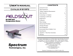
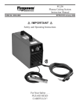
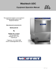
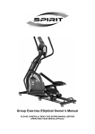
User Manual
Manufactured by:
Rimik
1079 Ruthven Street
Toowoomba QLD 4350
Australia
Ph. +61 438 135215
[email protected]
www.rimik.com
1. Warranty Term
Subject to the conditions set out below, Rimik warrants to the original purchaser that:
1.1
The Product will be free from defects in workmanship and materials under normal use
for a period of 1 year from the date of purchase.
2. Warranty Conditions
2.1
This warranty covers all parts found to be defective in workmanship and/or materials
during the warranty period and will be repaired or replaced at the discretion of the
manufacturer. Parts replaced will not be returned.
2.2
Rimik International Pty Ltd will not be responsible for any costs in connection with
freight or postage of replacement products or parts.
2.3
This warranty will be void and accordingly no claim of any nature whatsoever will be
enforceable against the manufacturer if the product is not installed and operated according to the printed instructions supplied with the product or if the product is subjected to abuse, neglect, misuse or an accident.
2.4
The manufacturer and/or distributor will not be liable for any incidental or consequential loss or damage arising from any cause whatsoever including but not limited to loss
or damage arising from the installation or operation of the product and/or the failure
of any part for any reason whatsoever.
2.5
There are no warranties expressed or implied except those stipulated above.
1
2
Contents
Warranty Terms
1
Introduction
Controls
Features
Understanding the Menu & Parameter Settings
4
4
5
6
Setting Up
Power on, power off
Time & Date
Display Format
Maximum Depth
Maximum Speed
Installing the Retrieval Software & USB Serial Port Driver
Setting Up for an Insertion
Cone Wear
7
7
8
8
8
8
8
8
9
Using the Penetrometer
Performing the Insertion
Reviewing Insertion Data
Clearing the Data Memory
Downloading Data to PC
Viewing Data on PC
9
9
9
10
10
10
Troubleshooting
11
Appendix
Load Calibration
Distance Calibration
Checking the Load
Checking the Distance
Battery
Load Cell Connection
12
12
12
13
13
13
13
Specifications
14
3
Introduction
The Rimik MicroCP Cone Penetrometer is used to measure soil density and hardness where
detailed study of the data is not needed. It has been designed for use by those who only require quick point and shoot values of soil hardness. It measures and records cone index values
of the load required to insert the cone through the soil and returns figures of the hardness of
the soil. These results can be viewed on the LCD screen or downloaded to PC via serial port
over a USB connection to the CP40II retrieval software. Up to 50 insertions may be recorded
with depths of up to 750mm and cone index values of up to 7500kPa.
Controls
LCD Screen
Up
Down
Cancel
Enter
Figure 1 - Front Panel
LCD Screen: The LCD Screen is a 2 x 16 character unit. All menus and data is displayed on it.
Up: The Up button moves up to the previous menu item or page of data. If already at the first
selection it will move to the last selection. It also increments numerical values.
Down: The Down button moves down to the next menu item or page of data. If already at the
last selection it will move to the first selection. It also decrements numerical values.
Cancel/Power off: The cancel button is used to enter and exit
the menu, cancel a selection and go back to the previous
menu. In the Start Screen (Figure 2) it also powers the
MicroCP off when held down until the unit beeps.
Figure 2 - Start Screen
Enter/Power on: The Enter button is used to power the MicroCP on when pressed and held
down until the unit beeps. The button also enters a chosen selection and starts an insertion
from the Start Screen.
4
DC Power Socket
USB Connector
Transducer
Reset Switch
Load Cell
Load Cell Connector
Figure 3 - Rear Panel
DC Power Socket: This DC Power Socket is used to connect the MicroCP to an
external battery charger to recharge the internal AAA batteries.
USB Connector: This USB socket is used to connect the MicroCP to a PC to download insertion
data to the supplied Retrieval Software.
Transducer: The Ultrasonic Transducer is used to measure the distance to the target by sending
and receiving ultrasonic waves.
Reset Switch: The Reset Switch is used to force the MicroCP into the power off state. Normally,
it is powered off by the Cancel/Power off button on the front panel. However because it is
kept in the power on state by the CPU and not simply a physical switch, there is a remote possibility that in the event of some malfunction occurring, the unit can still be forced into the
power off state.
Load Cell: The Load Cell responds to the force required to insert the cone into the soil and
sends a corresponding result back for the MicroCP to record.
Load Cell Connector: The Load Cell Connector is used to connect the load cell to the unit to record the force exerted by the shaft. It should never need to be disconnected by the user.
Features
Included Items & Accessories (Figure 4)
1 x MicroCP
1 x Shaft (2 pieces)
1 x Cone
1 x Target with Bush
2 x Handles
2 x Knobs for Handles
2 x 8mm Spanner
1 x 13mm Spanner
1 x ASAE Cone Wear Gauge
1 x Mains Battery Charger
1 x Serial Number Sticker, on MicroCP
1 x Users Manual
1 x CD (manual & retrieval software)
1 x Warranty Card
Optional Accessories (Figure 5)
Carry Case with Foam Insert
1m USB Cable
1.2m Car Charger Cable
Test Stand Bolt (used for load calibration)
5
Battery
Charger
Target
Handles
MicroCP
Knobs for
Handles
Cone
Spanners
Cone Wear
Gauge
Shaft
Figure 4 - Included Items & Accessories
Carry Case
USB Cable
Car Charger
Cable
Test Stand
Bolt
Figure 5 - Optional Accessories
Understanding the Menu & Parameter Settings
Review Data File
This allows the user to view the data from the last 50 insertions. The MicroCP displays this data
in numerical form.
Clear Data Memory
This allows the user to delete all the insertion data from the MicroCP.
Check Battery
The MicroCP displays the battery status as a percent of total battery charge. Note that as the
batteries age over time the reading may no longer reach 100% after charging.
6
Set Display Format
When reviewing insertion data on the MicroCP there are two different view formats to choose
from: With depth indication and without depth indication. With depth indication turned on the
MicroCP will display the depth of the data in the insertion on the top line and the corresponding data below on the bottom line. Only 3 depths of information will display per page display
requiring up to 10 pages to show the complete insertion data, see Figure 6. Without depth
indication the MicroCP displays actual insertion data on both lines, allowing 6 depths of information to display per page and requiring up to only 5 pages to show the complete insertion
data, see Figure 7.
Figure 6 - With Depth Indication
Figure 7 - Without Depth Indication
Set Maximum Depth
The Max Depth is the depth at which the MicroCP will complete an insertion. It can be set up to
a maximum of 750mm in 25mm intervals.
Speed Abort Menu
Because the MicroCP uses the ASAE standard S313.3 for measuring the soil density which specifies a minimum speed of 0.2 metres per minute and a maximum speed of 2 metres per minute,
the MicroCP has been included with the ability to enable speed abort alarms. The abort can be
disabled, however an audible beeping will let the user know that the cone index values may
not be an accurate representation of the actual soil density profile.
Set Clock Time & Date
Used to set the time and date since each insertion is tagged with the time and date.
Check Clock Time & Date
Used to check the time and date. If the MicroCP has been off for more than about 1 or 2 weeks
it will lose its time and date.
Calibration Menu
As well as containing the settings to calibrate the load and depth measurements, the calibration menu also includes checking both the load and depth in real time. See Appendix, page 12.
Setting Up
Power on
To turn the MicroCP on, simply press and hold the ‘Enter’ button until the unit beeps. The first
thing it will display on the LCD Screen is the model, version and serial number, before changing
to the Start Screen.
Power off
To turn the MicroCP off, simply press and hold the ‘Cancel’ button while the Start Screen is
displayed until the unit beeps and turns off. The ‘Cancel’ button will not turn the unit off in any
other menu, but rather it will go back to the preceding menu or exit back to the Start Screen.
7
Time & Date
Each time an insertion is made the time and date is attached to the insertion data. This enables
the user to determine when each insertion was made. The MicroCP uses a 24hour clock only,
this means that, for example 3.00pm is displayed as 15.00 hours.
To set the time, enter the menu by pressing ’Cancel’ from the Start Screen, scroll up or down
until ’Set Clock Time & Date’ is displayed and press ‘Enter’. The cursor will now be flashing over
the hours, next use the ‘Up’ or ‘Down’ buttons to change the hour and press ‘Enter’ to select
and move the cursor onto the next value to the right. In the same way, use the ‘Up’, ‘Down’
and ‘Enter’ buttons to select the remaining values including the date displayed in the DD/MM/
YY format on the second line. The ‘Cancel’ button will move the cursor back to previous selection on the left. Once the cursor gets to the last selection on the second line the ‘Enter’ button
will save the setting and exit back to the menu.
Display Format
To set the display format, enter the menu by pressing ’Cancel’ from the Start Screen, scroll up
or down until ’Set Display Format’ is displayed and press ‘Enter’. The current setting will be
displayed, press ‘Up’ or ‘Down’ to change it and press ‘Enter’.
Maximum Depth
To set the maximum depth, enter the menu by pressing ’Cancel’ from the Start Screen, scroll
up or down until ’Set Maximum Depth’ is displayed and press ‘Enter’. The current setting will
be displayed, press ‘Up’ or ‘Down’ to change it by 25mm increments and press ‘Enter’.
Speed Abort Menu
To setup the speed aborts, enter the menu by pressing ’Cancel’ from the Start Screen, scroll up
or down until ’Speed Abort Menu’ is displayed and press ‘Enter’. There are four settings; Too
Fast abort On/Off, Set Maximum Speed, Too Slow Abort On/Off and Set Speed Abort Delay
Time. For each setting, press ‘Enter’. The current setting will be displayed, press ‘Up’ or ‘Down’
to change it and press ‘Enter’. The maximum speed can be set from 1 to 15 metres per minute.
If the Too fast or Too Slow aborts are set to On then the MicroCP will abort an insertion automatically if the set speed is exceeded. The Speed Abort Delay Time is the time allowed for the
speed to be over or under the set abort limit. Please Note that to obtain ASAE standard S313.3
the Maximum speed of the obtained sample must be less than 2m per minute.
Setting Up for an Insertion
After setting the Parameters, check that the cone about to be used isn’t worn out, (see Cone
Wear below). Attach the handles and tighten the knobs finger tight. Assemble the 2 piece
shaft onto the load cell, just hand tight, they will only go on one way. Then before attaching
the desired cone, push the target onto the shaft. Once the shaft, cone and target are assembled, gently tighten the shafts to the load cell and the cone to the shaft. They do not need to
be really tight, this will just wear out the spanners and the flats on the shafts and cone. Just a
nudge is all that is required to stop them coming loose. Reverse this procedure to disassemble
the shaft assembly. Please Note: it is recommended that the user regularly check that the cone
and shaft assembly hasn’t come loose in any of the assembly points, when doing multiple insertions. There is always a chance the shaft assembly could come loose, if this happens, there
is a much greater chance of the shaft breaking, which may result in severe injury to the user.
8
Installing the Retrieval Software & USB Serial Port Driver
Insert the included CD into the CD/DVD drive, click on the Windows Start button and select My
Computer. Navigate to D:\ where D is CD/DVD drive and open it up. Click on the Readme text
file and follow the instructions.
Cone Wear
Excessive wear to the cone will cause incorrect readings of the soil
density profile. A Cone Wear Guide has been supplied for the user to
check that cone wear hasn’t exceeded the limit for accuracy.
If the cone slips through the small hole, see Figure 8, the cone must
be discarded. It is outside the 5% tolerance specified by the ASAE
standard. The cone wear guide also has cutouts for the user to
check that the side of the cone is not deformed excessively, as this Figure 8 - Cone Wear Guide
can also give incorrect readings of the soil. The cone should also be
discarded if this check shows the sides are excessively deformed.
Using the MicroCP
Performing the Insertion
Once the MicroCP has been assembled ready for an insertion, (see previous page on Setting up
for an Insertion and Cone Wear), the insertion can be performed by a single user.
Place the target over the selected spot, making sure the target sits reasonably level. Remove
any foliage from around the shaft and target, this ensures the ultrasonic transducer will not
pick up any incorrect depth fluctuations due to the foliage reflecting the ultrasonic waves.
Keeping the target on the ground, hold the weight of the MicroCP to stop the cone from sinking into the soil, the cone needs to be above the ground to start the insertion, otherwise the
MicroCP will show the error message ‘Too Close!, Data not Saved’. Once the insertion is
started, push the cone through the soil vertically, putting no sideways/lateral force against the
shaft following the hole made by the cone, smoothly and at a constant speed, aiming for 2
metres per minute or less (the speed is displayed on the LCD screen during the insertion), until
the insertion is finished at the maximum depth selected.
To record an insertion simply press ’Enter’ in the Start Screen. The number on the second line
of the display denotes the next file number.
Once the insertion has initiated, the ultrasonic transducer will emit a clicking sound as it produces the ultrasonic waves. The LCD screen will display the depth of the cone below ground
(as a positive number), and before the cone is inserted this number will be negative. Also displayed during the insertion is the current cone index in kPa and the insertion speed in metres
per minute. The user can abort an insertion by pressing the ‘Cancel’ button and the LCD screen
will display ‘Insertion Aborted...’, then ‘Keep Data?’ Press ‘Enter’ to keep the data or ‘Cancel’ to
discard it and the screen will display ‘Data Discarded’.
When the insertion has completed, the MicroCP will automatically enter the review data menu
selection to show the insertion just recorded in numerical form. Pressing ‘Enter’ or ‘Cancel’ will
take the user to the Start Screen ready for the next insertion.
9
Reviewing Insertion Data
The MicroCP provides the user with the ability to review the insertions stored in memory. To
review insertions stored, press ‘Cancel’ in the Start Screen to enter the menu, ‘Review Data
File’ will be displayed, so press ‘Enter’ again. If insertion data has been recorded, the file number will be displayed, press ‘Up’ or ‘Down’ to select the file to be displayed and press ‘Enter’. If
no data has been recorded, ‘No Data’ will be displayed before it automatically returns to the
menu. The data will now be displayed on the screen as per the Display format setting on page
7 & 8. Press ‘Up’ and ‘Down’ to move through the pages of data and press ‘Cancel’ or ‘Enter’ to
return to the previous menu.
Clearing the Data Memory
To clear the data memory, enter the menu by pressing ’Cancel’ from the Start Screen, scroll up
or down until ’Clear Data Memory’ is displayed and press ‘Enter’. The MicroCP will ask ‘Are you
sure?’, press ‘Enter’ to continue and erase the memory. Once finished, ‘Data Memory Erased’
will be displayed and it will automatically return to the previous menu.
Downloading Data to PC
To download the insertion data from the MicroCP, connect the MicroCP to the PC with a USB
cable and open the installed CP40II Retrieval Software on PC. Make sure the correct com port
is selected by going into settings, then communications, select the com port and press ok.
Next, click on download, then on start, select which files to download and the retrieval software will take control of the MicroCP to download the insertion data.
Viewing Data on PC
Once the insertion data has been downloaded, the user can select which file to display. Select
the file to be displayed and press the ‘Review View’ button then the ‘Insert 1’ button, the data
will be displayed with depth in millimeters on the X axis and force in kPa on the Y axis. The file
number, depth, time and date is displayed in the bottom left of the screen. The user also has
the ability to zoom in and out, move the graph up, down, left and right and rotate the graph.
10
Troubleshooting
Error/ Error Message
Cause
Remedy
Beeps while performing an insertion.
Maximum speed has been exceeded.
Keep a slower constant speed of
insertion.
Increase the max speed setting.
Insert aborted, keep
data?
Maximum Load exceeded.
Maximum Speed exceeded.
Minimum Speed exceeded.
Too Close.
Cancel button pressed.
See Max Load exceeded.
See Too fast.
See Too slow.
See Too Close.
Insertion doesn’t com- Distance not correctly calibrated.
plete.
Calibrate distance. See Appendix.
Fault.
Battery charging fault detected.
Return to Rimik or approved
dealer for battery replacement.
Low battery.
Battery voltage has fallen too
low.
Recharge battery.
Maximum Load exceeded!
Maximum load of 100kg
(7500kPa) has been exceeded.
Try keeping a slower constant
speed of insertion.
Soil too hard for MicroCP.
Memory full.
In built memory of 50 insertions
has been used.
Download data to PC and clear
memory.
No data.
No insertions recorded in memory.
Record insertion.
No load recorded.
Incorrect load calibration.
Load cell not connected.
Calibrate load. See Appendix.
Connect Load cell. This should not
normally be disconnected.
Too close!, data not
saved.
Cone below ground at start of
insertion.
Dirt or mud built up around cone.
Target not sitting on ground.
Foliage around shaft reflecting
ultrasonic waves.
Incorrect distance calibration.
Keep cone raised slightly to start
insertion.
Clear clumps of grass or dirt from
under target or around cone.
Clear foliage from around shaft.
Calibrate distance. See Appendix.
Too Fast!
Maximum set speed of insertion
exceeded, speed abort is turned
on.
Incorrect distance calibration.
Keep a slower constant speed of
insertion.
Increase maximum speed setting.
Turn speed abort off.
Calibrate distance. See Appendix.
Too Slow!
Minimum speed of 0.2 metres per Keep a faster constant speed of
minute exceeded.
insertion.
Incorrect distance calibration.
Calibrate distance. See Appendix.
11
Appendix
Load Calibration
The load calibration is essential to the MicroCP to record accurate cone index values. It comes
already calibrated, but it is advisable to periodically check the load calibration and recalibrate it
if necessary.
To calibrate the load, press ‘Cancel’ from the Start Screen to enter the menu, then use the ‘Up’
and ‘Down’ keys to scroll to ‘Calibration Menu’, use the ‘Up’ and ‘Down’ keys again to scroll to
‘Perform Load Calibration’ and press ‘Enter,’ the LCD screen will display ’Are You sure?’ Press
‘Cancel’ to exit back to the Calibration Menu, or ‘Enter’ to proceed with the calibration. The
existing calibration will be lost, ready for a new one to be entered. The LCD screen will display
‘Zero Load, Push Enter..’
Hold the MicroCP with no shaft or cone attached, and the load cell pointing straight down, and
press the ‘Enter’ button when the value on the screen has settled. The LCD screen will now
display ‘Test Load, Push Enter..’
Attach the MicroCP to a stand, screwing the Test Stand Bolt
into the base of the Load Cell to keep the MicroCP upright
and steady (Figure A-1). Next, add the weights as evenly as
possible to avoid putting too much uneven stress on the
load cell and risking the weights falling off or toppling the
stand over.
Once the load has steadied, press the ‘Enter’ button to set
the weight, taking care not to alter the weight by pressing
the button. Enter the total weight (weight of the MicroCP,
Figure A-1
attached handles and the weights all combined), using the
‘Up’ or ‘Down’ buttons to adjust each number and pressing ‘Enter,’ to move the flashing cursor
over the next number until the weight is entered and the screen shows ‘Load Calibration Complete’.
Distance Calibration
The distance calibration is essential to the MicroCP to record accurate
depth measurements. It comes already calibrated, but it is advisable to
periodically check the distance calibration and recalibrate if necessary.
To calibrate the distance, first assemble the MicroCP, then press ‘Cancel’
from the Start Screen to enter the menu, then use the ‘Up’ and ‘Down’
keys to scroll to ‘Calibration Menu’, use the ‘Up’ and ‘Down’ keys again
to scroll to ‘Perform Distance Calibration’ and press ‘Enter,’ the LCD
screen will display ’Are You sure?’ Press ‘Cancel’ to exit back to the Calibration Menu, or ‘Enter’ to proceed with the calibration. The existing
calibration will be lost, ready for a new one to be entered. The LCD
screen will display ‘Target Height’. Use the ‘Up’ or ‘Down’ buttons to
select the target height and press ‘Enter,’ (if using the standard target
this value should be set to 35mm). Next the display will show ‘Dist
Cone>Trans’. Use the ‘Up’ or ‘Down’ buttons to select the distance and
press ‘Enter,’ (if using the standard shaft this value should be set to
976mm). Next you will hear the ultrasonic transducer operating, emitting a clicking sound, hold the assembled MicroCP off the ground so
that the target rests on the base of the cone, as shown in figure A-2. The
LCD screen will display ‘Press Enter’, press ‘Enter’ once the MicroCP is
12
Figure A-2
steady. Enter the distance using the ‘Up’ or ‘Down’ buttons to select the desired value and
press ‘Enter,’ (if using the standard shaft and target this value should be set to 970mm). The
LCD screen will display ‘Dist Calibration Complete’.
Checking the Load
This function allows the user to check the load applied to the load cell. Press ‘Cancel’ from the
Start Screen to enter the menu, then use the ‘Up’ and ‘Down’ keys to scroll to ‘Calibration
Menu’, use the ‘Up’ and ‘Down’ keys again to scroll to ‘Check Load Calibration’ and press
‘Enter,’ The load will be displayed in kilograms.
Checking the Distance
This function allows the user to check the distance measured by the ultrasonic transducer. To
check the distance, press ‘Cancel’ from the Start Screen to enter the menu, then use the ‘Up’
and ‘Down’ keys to scroll to ‘Calibration Menu’, use the ‘Up’ and ‘Down’ keys again to scroll to
‘Check Distance Calibration’ and press ‘Enter,’ The time (of flight of the ultrasonic wave), distance measured and the depth calculated will be displayed in microseconds and millimeters
respectively.
Battery
The MicroCP uses 2 900mAh AAA NiMH rechargeable batteries. It allows up to 150 insertions.
The battery life can and should be checked during field use, in the menu by scrolling to ‘Check
Battery’ and pressing ‘Enter’, the battery life is displayed as a percentage of full capacity. If the
battery voltage falls within around 5 to 10%, ‘Low Battery’ will be displayed (in standby, not
while in battery check). At this stage, insertions will no longer be allowed. At around 0 to 5%,
the MicroCP will automatically beep and display ‘Power Off’, before powering off (in standby,
not while in battery check). The battery should be charged for approximately 1.5 to 2 hours to
fully charge the battery again.
Any well regulated power supply from 6 to 16 volts can be used to charge the MicroCP, as long
as the plug is connected as per Figure A-3 below and has an inside diameter of 2.1mm, and an
outside diameter of 5.5mm.
Stored data in the MicroCP is non-volatile and will not be effected by powering off.
Figure A-3
Load Cell Connection
The Load Cell is connected as per Figure A-4 below.
Figure A-4
13
Specifications
2.65
4.4
431 x 1063 x 85
448 x 362 x 110
7500, 100
0.03
750
25
50
-10-75
9600
2 x 16
900, up to 150
Weight (assembled) (kg)
Weight (in case) (kg)
Dimensions (assembled) (mm)
Case Dimensions (mm)
Maximum Cone Index (kPa, kg)
Resolution (kg)
Maximum Insertion Depth (mm)
Interval Spacing (mm)
Memory Capacity (no. of insertions)
Operating Temperature (°C)
Baud Rate/Download speed (bps)
Screen Resolution (characters)
Battery Life (mAh, insertions)
Conforms to Standard ASAE S313.3 feb99
12.83, 130
9.53
Cone Size (dia. mm, area mm²)
Shaft Size (dia. mm)
Copyright by Rimik
www.rimik.com
14