1
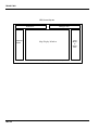
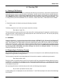
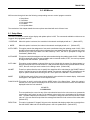
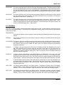
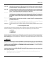
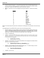
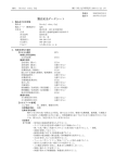
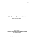
TRANSIT NIS
Transit N I S
User Manual
Version 9.0
Transit Network Information System
FOR
IBM PC and Compatible Microcomputers
Selected UNIX-Based Workstations
Distributed by:
THE URBAN ANALYSIS GROUP
TRANSIT NIS
TRANSIT NIS
Transit NIS
TABLE OF CONTENTS
Page
1.0 Background and Introduction . . . . . . . . . . . . . . . . . . . . . . . . . . . . . . . . . . . . . . . . . . . . . . . . . . . . . . . . . . . . . 1-1
2.0 Program Usage and Basic Concepts . . . . . . . . . . . . . . . . . . . . . . . . . . . . . . . . . . . . . . . . . . . . . . . . . . . . . . . 2-1
3.0 NIS Files . . . . . . . . . . . . . . . . . . . . . . . . . . . . . . . . . . . . . . . . . . . . . . . . . . . . . . . . . . . . . . . . . . . . . . . . . . . .
3.1 Transit Network Files . . . . . . . . . . . . . . . . . . . . . . . . . . . . . . . . . . . . . . . . . . . . . . . . . . . . . . . . . . . .
3.2 Transit Loaded Legs Files . . . . . . . . . . . . . . . . . . . . . . . . . . . . . . . . . . . . . . . . . . . . . . . . . . . . . . . . .
3.3 Transit Access Link Files . . . . . . . . . . . . . . . . . . . . . . . . . . . . . . . . . . . . . . . . . . . . . . . . . . . . . . . . .
3.4 User Profile Files . . . . . . . . . . . . . . . . . . . . . . . . . . . . . . . . . . . . . . . . . . . . . . . . . . . . . . . . . . . . . . .
3.5 Configuration Files . . . . . . . . . . . . . . . . . . . . . . . . . . . . . . . . . . . . . . . . . . . . . . . . . . . . . . . . . . . . . .
3-1
3-1
3-1
3-1
3-1
3-1
4.0 Executing TNIS . . . . . . . . . . . . . . . . . . . . . . . . . . . . . . . . . . . . . . . . . . . . . . . . . . . . . . . . . . . . . . . . . . . . . . .
4.1 Starting a TNIS Session . . . . . . . . . . . . . . . . . . . . . . . . . . . . . . . . . . . . . . . . . . . . . . . . . . . . . . . . . .
4.1.1 Extended DOS, Windows Command Line, and UNIX . . . . . . . . . . . . . . . . . . . . . . . . . . . . .
4.1.2 WINDOWS . . . . . . . . . . . . . . . . . . . . . . . . . . . . . . . . . . . . . . . . . . . . . . . . . . . . . . . . . . . .
4.2 Responding to Preliminary Prompts . . . . . . . . . . . . . . . . . . . . . . . . . . . . . . . . . . . . . . . . . . . . . . . . .
4.3 Getting Started with Test Data . . . . . . . . . . . . . . . . . . . . . . . . . . . . . . . . . . . . . . . . . . . . . . . . . . . . .
4.4 Demonstration Versions . . . . . . . . . . . . . . . . . . . . . . . . . . . . . . . . . . . . . . . . . . . . . . . . . . . . . . . . . .
4-1
4-1
4-1
4-1
4-2
4-2
4-3
5.0 NIS Icons . . . . . . . . . . . . . . . . . . . . . . . . . . . . . . . . . . . . . . . . . . . . . . . . . . . . . . . . . . . . . . . . . . . . . . . . . . .
5.1 Stop Icon . . . . . . . . . . . . . . . . . . . . . . . . . . . . . . . . . . . . . . . . . . . . . . . . . . . . . . . . . . . . . . . . . . . . .
5.2 Menu Icons . . . . . . . . . . . . . . . . . . . . . . . . . . . . . . . . . . . . . . . . . . . . . . . . . . . . . . . . . . . . . . . . . . . .
5.3 Window Icons . . . . . . . . . . . . . . . . . . . . . . . . . . . . . . . . . . . . . . . . . . . . . . . . . . . . . . . . . . . . . . . . . .
5-1
5-1
5-1
5-1
6.0 NIS Menus . . . . . . . . . . . . . . . . . . . . . . . . . . . . . . . . . . . . . . . . . . . . . . . . . . . . . . . . . . . . . . . . . . . . . . . . . .
6.1 Setup Menu . . . . . . . . . . . . . . . . . . . . . . . . . . . . . . . . . . . . . . . . . . . . . . . . . . . . . . . . . . . . . . . . . . .
6.2 View Menu . . . . . . . . . . . . . . . . . . . . . . . . . . . . . . . . . . . . . . . . . . . . . . . . . . . . . . . . . . . . . . . . . . . .
6.3 Link Update Menu . . . . . . . . . . . . . . . . . . . . . . . . . . . . . . . . . . . . . . . . . . . . . . . . . . . . . . . . . . . . . .
6.4 Post Menu . . . . . . . . . . . . . . . . . . . . . . . . . . . . . . . . . . . . . . . . . . . . . . . . . . . . . . . . . . . . . . . . . . . .
6.5 Line Update Menu . . . . . . . . . . . . . . . . . . . . . . . . . . . . . . . . . . . . . . . . . . . . . . . . . . . . . . . . . . . . . .
6-1
6-1
6-2
6-3
6-5
6-6
7.0 NIS Configuration Files . . . . . . . . . . . . . . . . . . . . . . . . . . . . . . . . . . . . . . . . . . . . . . . . . . . . . . . . . . . . . . . . .
7.1 NEDS.CFG . . . . . . . . . . . . . . . . . . . . . . . . . . . . . . . . . . . . . . . . . . . . . . . . . . . . . . . . . . . . . . . . . . . .
7.2 TNDMENU.CFG . . . . . . . . . . . . . . . . . . . . . . . . . . . . . . . . . . . . . . . . . . . . . . . . . . . . . . . . . . . . . . . .
7.3 TNDATTR.CFG . . . . . . . . . . . . . . . . . . . . . . . . . . . . . . . . . . . . . . . . . . . . . . . . . . . . . . . . . . . . . . . .
7.4 TNDLINA.CFG . . . . . . . . . . . . . . . . . . . . . . . . . . . . . . . . . . . . . . . . . . . . . . . . . . . . . . . . . . . . . . . . .
7-1
7-1
7-3
7-3
7-3
TRANSIT NIS
TRANSIT NIS
1.0 Background and Introduction
NIS (Network Information System) is a flexible, interactive graphics editor for displaying and maintaining spatial data.
NIS accepts information used for many aspects of transportation planning, including highway and transit network
descriptions, and traffic analysis zone and census tract data. It is fully integrated with the highway and transit network
databases utilized by TRANPLAN.
NIS has two basic elements: HNIS for highway networks and TNIS for transit networks.
NIS is available in both a "standard" edition and an "extended" edition. Both editions provide the user with a flexible
set of thematic mapping tools which are accessed via icons and menus. Standard edition provides tools for displaying
and updating network node and link attributes using colors and patterns. For example, link colors could represent facility
types and bandwidths could represent volumes. Attribute values can also be posted. Attributes can be interactively
updated for single links or on a global basis (including selected link subsets) via a user update template. Subareas can
be extracted using point or link cordons. Extended edition provides all the link/node display and update capabilities of
standard edition, in addition to capabilities for defining, displaying, and updating up to 15 types of areas, (e.g., traffic
analysis zones, census tracts). Color and fill patterns of areas can be set based on value ranges for selected area
attributes. For example, area color could represent population and pattern could represent employment.
NIS minimizes the time to prepare and change transportation networks and presents modeling results quickly via screen
displays. NIS has the following features:
o Sub-area extraction
o Color displays
o Volume/capacity analysis
o Link loadings
o Transit line loadings
o Network zoom and pan
o Turning movement diagrams
o Restore last/next views
o Network load comparisons
o Interactive network editing
o Bandwidth displays
o Minimum path determination
o Global editing templates
o Turn prohibitors
o User-controlled colors
o Icon and menu-driven
o Link attribute posting
o Volume/capacity difference bands
Transit NIS is menu-driven with five basic menus: a "setup" menu for program specifications; a "view" menu for
displaying various network characteristics, (such as shortest path between two points or bandwidths based on link
attributes); an "update" menu, for network modifications; a "posting" menu for setting annotation criteria; and a "line"
menu for defining and editing transit line attributes.
TNIS 1-1
TRANSIT NIS
NOTES:
TNIS 1-2
TRANSIT NIS
2.0 Program Usage and Basic Concepts
NIS utilizes icons, menus and dialogue queries to control program execution and allocation of network files. While NIS
is running, the principle source of program control is through the graphics cursor. The graphics cursor is moved around
the screen to point at particular objects which are selected for specific purposes. The user terminal must be equipped
with a pointing device (mouse or digitizer) for cursor control. An option is selected by depressing any button on the
pointing device, (hereinafter referred to as a "mouse"). This sequence of point and select is referred to as a "pick" in
the remainder of this manual. When a pick is requested by NIS, the user positions the cursor and depresses a mouse
button at the desired location.
During some commands, the program may require the entry of alphanumeric data, such as a file name or zone number.
When this occurs, a prompt appears in the upper right corner of the NIS screen display requesting the desired
information. The response is entered and terminated by depressing the RETURN (or ENTER) key.
A command is activated by picking the location of the command as it appears in the command menu. When a
command is picked, it becomes "turned-on", meaning its menu entry is highlighted and the command begins to execute.
Commands are automatically turned off if invoked incorrectly, or in some cases, when they are aborted. If a command
is not behaving as expected, the user should ensure that it is on. A good rule to follow is, if a command's menu entry
is highlighted, the command is either in the process of executing, or it is waiting for further action from the user.
The behavior of a command falls into one of several categories depending on the purpose of the command:
o
Commands which control the reading and writing of network files execute once via user-directed
prompts.
o
Commands which adjust the display window execute once, and may be executed within most
commands.
o
Commands which enable different display characteristics are toggled on and off like light switches and
remain active while other commands execute.
o
Commands which perform editing or which adjust the color menu, usually stay turned on, allowing
repeated executions. In general, the user can switch freely between commands in this last category
without turning the current one off.
Several of the commands, (e.g., DRAW NETWK, ZOOM IN, ZOOM OUT, PAN, LAST VIEW), cause NIS to create an
image in the display area. The user can interrupt the drawing process at any time by pressing the right hand button on
the mouse and holding it until the drawing operation stops. After the drawing has stopped, the button can be released
and a prompt will appear in the dialogue area.
Stop Draw? (Y/N)
Typing a "Y" and the RETURN key will stop the current operation and allow the user to select a different function.
Typing an "N" or any other character followed by the RETURN key will cancel the interrupt and allow drawing to
continue. (For a VAX/VMS system only -- the STOP DRAW function is initiated by pressing the "CTRL" and "D" keys
simultaneously.)
The figure on the following page illustrates the basic layout of an NIS screen. Each part of the screen has a different
purpose. After only a short period of time, the user should become familiar with all aspects of the screen.
TNIS 2-1
TRANSIT NIS
NIS Screen Layout
ICON Area
Command
Menu
Dialogue Area
Map Display Window
The Urban Analysis Group - NIS (Version XXX)
TNIS 2-2
Color
Menu
or
Status
Area
TRANSIT NIS
3.0 NIS Files
There are five basic types of files which are used, created or modified by Transit NIS:
o
o
o
o
o
Transit Network Files
Transit Loaded Legs Files
Transit Access Link Files
User Profile Files
Configuration Files
3.1 Transit Network Files
Transit network files are in TRANPLAN format. These files contain the links and link attributes that comprise the transit
network. Refer to the TRANPLAN User Manual for instructions on creating network files. (BUILD TRANSIT NETWORK)
3.2 Transit Loaded Legs Files
Transit loaded legs files are in TRANPLAN format. These files contain loaded "leg" volumes for each transit line. Refer
to the TRANPLAN User Manual for instructions on creating loaded legs files. (LOAD TRANSIT NETWORK)
3.3 Transit Access Link Files
Transit access link files are in TRANPLAN format. These files contain loaded access link volumes for mode 1, mode
2 and mode 3 links. Refer to the TRANPLAN User Manual for instructions on creating access link files. (LOAD
TRANSIT NETWORK)
3.4 User Profile Files
NIS allows the user to save session setup parameters for re-use through Setup Menu options, READ UPRF and SAVE
UPRF. Steps to use these options are described in Section 6.1 -- Setup Menu.
The following characteristics of an NIS session are saved in the user profile:
o
Settings for color display of links based on mode(s) and on volume to capacity ratios.
o
Bandwidth ranges from the BAND VOL, BAND CAP, BAND V/C and BAND V-C commands, (e.g.,
bandwidths for link volumes and capacities).
o
User window definition and ID's (up to four windows).
User profiles are saved with a user specified ID of up to eight characters and an NIS-supplied suffix of ".UPF".
3.5 Configuration Files
Configuration files define the types, valid value ranges and file formats for link attributes; control the display of links;
and perform various other functions which are detailed in Chapter 7, NIS Configuration Files.
TNIS 3-1
TRANSIT NIS
NOTES:
TNIS 3-2
TRANSIT NIS
4.0 Executing TNIS
4.1 Starting a TNIS Session
Working directories should be created for maintaining NIS data files, and optionally, customized configuration files.
Working directories may be located anywhere on the system, and NIS can be executed from the working directories.
(The "test" directory, which is created when URBAN/SYS software is installed, is an example of a working directory.)
The \URBANSYS directory, which contains NIS software, should never be used as a working directory. After
a working directory has been established with, at a minimum, a transit network file, a TNIS session can be initiated.
c
A Transit NIS session is initiated by entering the following command:
TNIS
TNIS then prompts the user for the input transit network file as follows:
Enter Name of Input File >
The user responds by entering the file name of the network file, including path name if appropriate, and NIS checks to
see if the file exists. If the file does not exist, NIS prompts the user to correct the file name. The user may also specify
"NONE" or "none" to exit NIS at this point.
4.1.2 WINDOWS
Support for Windows 3.1.x has been discontinued with the release of URBAN/SYS 9.0. Windows 95 and Windows NT
installation options and procedures may be found on the UAG Web site at “www.uagworld.com” under the URBAN/SYS
page. After installation, the TNIS window is opened by positioning the mouse cursor over the TNIS icon and doubleclicking the mouse button. (NOTE: After a session is started, NIS functions are separate from the window and the
window menu. Because of this separation of window application and NIS session, an NIS session must be terminated
by selecting the NIS "STOP SIGN" icon before starting a new session or exiting the window. This is done by
selecting the stop sign icon within NIS.)
4.2 Responding to Preliminary Prompts
After providing TNIS with an input network file name, the user must respond to some additional prompts before any
displays can be generated or editing performed.
The first prompt is required for calculating distances for links which are added or modified during the session.
Enter Units per Mile Value>
Enter the number of coordinate units per mile for your network so NIS can automatically calculate distances for new or
modified links. For example, if a one mile link in your network runs due east and west, (i.e., y-coordinate values are the
same for the A and B nodes), then the difference in the x-coordinate values for the A and B nodes would be the number
of coordinate units per mile.
After providing NIS with the coordinate units per mile value, the following prompt appears:
Do you wish to plot loaded volumes (Y/N)?
If transit loadings are to be displayed, the user should answer "Y" and TNIS will prompt for the name of the loaded legs
file as follows:
TNIS 4-1
TRANSIT NIS
Enter Name of Input File>
This is the name of the file, including path name if appropriate, which contains the transit line volumes from the
TRANPLAN function LOAD TRANSIT NETWORK.
After providing NIS with the loaded legs file name, the following prompt appears:
Do you wish to plot non-transit volumes (Y/N)>
If volumes for non-transit links (modes 1 through 3) are to be displayed, the user should answer "Y" and TNIS will prompt
for the name of the name of the non-transit volumes file as follows:
Enter Name of Input File>
This is the name of the file, including path name if appropriate, which contains the transit access link volumes from the
TRANPLAN function LOAD TRANSIT NETWORK.
The mouse cursor will then appear, and NIS is ready for the user to pick an icon.
4.3 Getting Started with Test Data
A sample transit network and corresponding files for loaded legs and non-transit walk loads have been provided to assist
the user in becoming familiar with the operation of Transit NIS. These files are located in the \UAGUSER\TEST
subdirectory for PC versions of the software, and in the URBANSYS.=TEST subdirectory for other versions.
To begin a sample Transit NIS session:
1)
For PC environments, make sure the mouse driver has been installed.
2)
Make the TEST (or =test) subdirectory the current working directory.
3)
Initiate a TNIS session as per the instructions provided in the previous section, specifying FTOWNTRN
as the input network. (This is the transit network created by the HUDNET.CTL TRANPLAN control file.
The TRLOAD.LGS and TRLOAD.WLK files are created by the TRLOAD.CTL TRANPLAN control file.)
Provide the responses indicated below to the preliminary prompts:
Transit NIS Prompt
User Response
Enter Units per Mile Value>
100
Do you wish to plot loaded volumes (Y/N)?
Y
Enter Name of Input File>
TRLOAD.LGS
Do you wish to plot non-transit volumes (Y/N)>
Y
Enter Name of Input File>
TRLOAD.WLK
The mouse cursor will appear in the center of the screen after the input file(s) have been read in and NIS is ready to
process user display and edit requests.
4.4 Demonstration Versions
The installation and program execution procedures for the demonstration version of Transit NIS are the same as for the
production version. The only difference is that the user cannot save a network that has been modified during the
TNIS 4-2
TRANSIT NIS
session. The sample network and corresponding loaded legs and walk links files described in the previous section,
(FTOWNTRN, TRLOAD.LGS and TRLOAD.WLK), are included in the demonstration package and located in the TEST
(or =test) subdirectory.
TNIS 4-3
TRANSIT NIS
5.0 NIS Icons
Transit NIS utilizes 13 icons to control program execution, options and user-specified windows. These icons are
constantly displayed in the upper left corner of the screen for invocation at any time during an NIS session:
I1) A "STOP SIGN" to exit NIS.
I2) An "EASEL" to load the Setup Menu.
I3) An "EYEGLASS" to load the View Menu.
I4) A "PENCIL/ERASER" to load the Link Update Menu.
I5) An "ANNOTATED LINK" to load the Post Menu.
I6) A "TRANSIT LINE" (with terminals) to load the Line Update Menu.
I7) For future use.
I8) For future use.
I9) A "SCREEN" icon to redefine the view area and retain the current menu and status area.
I10-I13)
Four "WINDOW PANE" icons for saving selected displays of the network and/or polygons.
Each of these 13 icons can be placed in one of the following three icon categories:
o A Stop Icon
o Menu Icons
o Window Icons
5.1 Stop Icon
The first icon is a stop sign which is selected when the user wishes to terminate an NIS session. This icon is activated
by a double-click. If any changes have been made to the network, the user is prompted to enter a new file name. If a
file specified by the user already exists, then the user must give another file name. A response of "NONE" or "none"
tells NIS the updates for the network are not to be saved. If changes have not been made to the network, NIS
immediately returns control to the operating system when the stop icon is picked.
5.2 Menu Icons
Selection of any of the menu icons with the cursor will cause a menu to be displayed on the left side of the NIS screen
display. A menu item can then be picked. The options and commands for each of the menus are discussed in detail
in the next chapter -- "NIS Menus".
5.3 Window Icons
Up to four user windows can be defined for each NIS session. When a display area has been created which the user
wishes to save, the user picks any of the four "window pane" icons displayed at the top of the screen and is prompted
for a three-character ID to be used to identify the window. This ID is then displayed below the selected icon. The user
can continue with other NIS functions, and then at a later time, restore a window to the display area. User window
settings are saved as part of user profiles, so the same windows can be restored in subsequent NIS sessions.
TNIS 5-1
TRANSIT NIS
NOTES:
TNIS 5-2
TRANSIT NIS
6.0 NIS Menus
NIS icons two through six have the following corresponding menus to control program execution:
o
o
o
o
o
Setup Menu
View Menu
Link Update Menu
Post Menu
Line Update Menu
The remainder of this chapter details the menu options associated with each of these icons.
6.1 Setup Menu
This menu is utilized to control various display and update options in NIS. The commands available on this menu are
"toggled" ON (highlighted) and OFF.
* CENTROID
When this option is selected, the centroids in the network are displayed with an '*'. (Default OFF)
o NODE
When this option is selected, the nodes in the network are displayed with a 'o'. (Default OFF)
AUTO CORD
This option controls the assignment of new node coordinates during the updating mode of NIS. If ON,
then NIS will automatically assign the coordinates of any new nodes (based on the "units per mile" value
provided by the user at the start of the NIS session); if OFF, the user is prompted to assign the
coordinates. (Default ON)
AUTO NODE
This option controls the assignment of new node numbers during the updating mode of NIS. If ON, then
NIS will automatically select the next available node or centroid number; if OFF, the user is prompted
to assign new node numbers. (Default ON)
AUTO LINK
This option controls whether nodes and links are to be picked with the mouse (for display/update), or
NIS is to prompt the user for node numbers. If ON, then nodes and links will be picked with the mouse;
if OFF, the user must input node numbers in the dialogue area. (Default ON)
AM NET
These four options allow the user to specify line capacities will be calculated on the PM NET basis of
service frequencies input for that particular period. Persons per vehicle NIT NET capacities can be
input for specific modes and lines using the SET PPV option in the MID NET Transit Line Menu.
MODE
If "ON" then the mode of links is used as the basis for color selection for network display. Multi-modal
links appear in the highest mode on the respective links.
CHNG COLOR This option is used in conjunction with the MODE option of the Setup Menu. When this option is
selected, the color options are displayed in the color menu area of the screen with a link mode table
displayed below the color selection:
012345678
0 NNNBNNNNN
The user positions the cursor into any of the color selection boxes in the color menu area, presses the
mouse button and "pokes" as many of the attribute values which are to be displayed in the selected
color. The table is depicted as units across. For example, to assign the color blue to a link with a mode
value of 3, the user would first pick the blue rectangle and then the fourth column of the values table.
(Default OFF)
DEPICTION
This option is selected if "shaped" links are to be depicted with shaping rather than as straight lines.
See the SHAPE LINK and CLR SHAPE options in the Link Update Menu. (Default OFF)
TNIS 6-1
TRANSIT NIS
TNIS 6-2
TRANSIT NIS
READ UPRF
This option allows the user to read in a previously saved session profile. The session profile contains
the user selected settings for link colors, bandwidths and window definitions. After selecting this option,
the user is prompted for an ID of up to eight characters. If the requested profile is found, the screen
is refreshed and any previously saved user window ID's are displayed at the top of the screen. (Default
OFF)
SAVE UPRF
This option allows the user to save the current parameter settings of an NIS session for later recall as
the user profile for the current session. For further information about user profiles, see the above
description of READ UPRF. (Default OFF)
INV VIDEO
This option allows the user to reverse the black and white areas on the screen. Selecting inverse video
will change the background color of the menu and map display windows from black to white. This is
useful for highlighting some colored network displays. A second selection of the option will return the
screen to its default display colors. (Default OFF)
6.2 View Menu
This menu is utilized to specify various transit network display options in NIS. A transit network is viewed as a picture
drawn in the map display window. The window may be adjusted to enlarge, reduce or move around to different parts
of the network image.
DRAW NETWK
If this option is selected, the entire network is drawn including any updates performed during the current
session.
REDRAW
If this option is selected, the current window is redrawn including any updates performed during the
current session.
CLR SCREEN This option is utilized to clear the entire screen and restore just the icon and window area boundaries.
For direct connection to a computer, this option would rarely be required; however, for dial-up access,
this command could be used to redraw the entire screen if it becomes corrupted by extraneously
transmitted characters.
ZOOM IN
To enlarge a user-specified portion of the picture in the display window, pick ZOOM IN once to turn it
ON. NIS prompts the user to pick the upper left and lower right corners of a new view area in the
display window. Those points form the opposite corners of a box which is expanded as much as
possible to fit, centered, within the display area. Failure to pick two points in the display window will
abort the ZOOM IN command.
ZOOM OUT
To shrink a portion of the picture in the display window, pick ZOOM OUT once to turn it ON. NIS
prompts the user to pick the upper left and lower right corners of a new "box" in the display window.
NIS fits the current window into the "box" and fills in the rest of the window with the environs about the
current window. Failure to pick two points in the display window will abort the ZOOM OUT command.
PAN
To pan the display window relative to the current picture, pick PAN to turn it ON. NIS prompts the user
to pick two points in the display window. The first pick is any point in the window. The second pick is
the desired location of that point in the redrawn window. Failure to pick two points within the display
window will abort PAN.
LAST VIEW
For restoring previous pictures in the display window. The display is redrawn using the "backward"
window definition. LAST VIEW may be executed up to five times to restore the previous five display
windows. This is a circular command -- after five selections, the current view is displayed again.
NEXT VIEW
For restoring previous pictures in the display window. The display is redrawn using the "forward"
window definition. NEXT VIEW may be executed up to five times to restore the previous five display
windows. This is a circular command -- after five selections, the current view is displayed again.
TNIS 6-3
TRANSIT NIS
WIN BY CRD
Used to select specific X and Y values for the minimum and maximum display window coordinates.
Pick WIN BY CRD to turn on this option. NIS prompts the user for the minimum and maximum X and
Y coordinate values. When all four values have been entered, the display is redrawn with the best
possible fit. Failure to properly enter any value will abort this option.
For user convenience, the preceding View Menu commands, which are most frequently used, are repeated on the Link
Update Menu and the Line Update Menu.
BAND VOL
This option selects volume as the link attribute to be used for bandwidth plotting. Typically, after picking
this option, the user would select the NM OF BAND or CHNG BAND options to modify bandwidth
scaling.
BAND CAP
This option selects capacity as the link attribute to be used for bandwidth plotting. (Capacity is persons
per vehicle, PPV, times vehicles per hour.) Typically, after picking this option, the user would select
the NM OF BAND or CHNG BAND options to modify bandwidth scaling.
BAND V/C
This option selects the volume/capacity ratio as the link attribute to used for bandwidth plotting.
(Capacity is persons per vehicle, PPV, times vehicles per hour.) Typically, after picking this option, the
user would select the NM OF BAND or CHNG BAND options to modify bandwidth scaling.
BAND V-C
This option specifies that the difference between volume and capacity will be used to determine
bandwidth colors. Links where capacity exceeds volume are displayed in the color green. If volume
exceeds capacity, the link is displayed in red.
COLOR V/C
This options specifies that volume/capacity ranges will be used to determine bandwidth colors.
CHNG BAND
When this option is selected, the user moves the cursor to the bandwidths displayed in the status area
and changes the bandwidth range values. The value to be changed is picked using the mouse and NIS
prompts for a value to be entered in the dialogue area -- followed by the RETURN key. To scale
bandwidths linearly, the user should only enter the minimum and maximum values desired.
Intermediate values will be calculated. Any link with a value not within the specified ranges, will not be
displayed. If the user enters a value in any single range and leaves all other values as "0", NIS will
automatically calculate proportional values for the "0" ranges. The values will be automatically changed
when the user exits the CHNG BAND function by picking the FINISHED box in the lower right hand
corner of the screen.
NM OF BAND When this option is specified, the user is prompted for the number of bands to be used for the particular
bandwidth option specified. The ranges selected will be displayed along the right-hand side of the
screen. The user may specify from one to eight bands.
POST LINK
When this option is turned on, the user may select individual links for posting. All posting options
toggled to "ON" in the Post Menu are displayed for the selected links. This option and the AUTO POST
option are mutually exclusive.
AUTO POST
When this option is turned on, all links of the displayed network will include posting of all options toggled
to "ON" in the Post Menu. This option and the POST LINK option are mutually exclusive.
6.3 Link Update Menu
This menu is utilized to pick the various transit link update options in NIS. A transit network is viewed as a picture drawn
in the map display window. The window may be adjusted to enlarge, reduce or move around to different parts of the
network image.
Many of the options described in the Link Update Menu section utilize the auto repeat facility. This means that after the
command is selected it remains active until it is reselected. For example, the ADD NODE command will continue to
prompt the user for new node locations until it is explicitly switched off. These commands are specifically identified as
"Auto Repeat" commands.
TNIS 6-4
TRANSIT NIS
The first group of options that appears on the Link Update Menu is identical to the first group of options on the View
Menu. These options, (DRAW NETWORK, REDRAW, CLR SCREEN, ZOOM IN, ZOOM OUT, PAN, LAST VIEW,
NEXT VIEW and WIN BY CRD), are most frequently used and are repeated on several menus as a user convenience.
Refer to Section 6.2, View Menu, for detailed descriptions of these options. Options unique to the Link Update Menu
are described below.
SHAPE LINK
This option is used to define the points that a link is to be shaped with for display purposes. Link
attributes, (e.g., distance, speed, etc.), are not affected. The DEPICTION option in the Setup Menu
must be selected if links are to be displayed with shaping.
CLR SHAPE
This option is used to delete shape points associated with a given link, as defined with the SHAPE LINK
option. Links without shape points are displayed as straight lines.
LIST ATRIB
After this option is picked, the user positions the cursor to any point on a link to list it's attributes. The
user is prompted for the A-node of the link and all attributes of the link in the A to B direction are
displayed in the status area. (Refer to Post Menu for detailed descriptions of link attributes and display
conventions.)
CHNG ATRIB After picking a link using the LIST ATTRIB option, the user may pick this option to change link
attributes. The user picks the attribute value in the status area, and NIS will prompt for a new value.
(Note: When a link speed is updated, NIS automatically updates the corresponding link time. Similarly,
when a link time is updated, NIS automatically updates the corresponding link speed.) This is an Auto
Repeat command.
POST NODE
To display the node number(s) for any node(s) in the display window, this option is picked. When the
cursor is positioned at the desired node and the mouse button is depressed, the associated node
number is displayed. This is an Auto Repeat command.
FIND NODE
This option is picked to find any node in the network. NIS prompts the user for the desired node
number. If the node is within the current display area, the node number is displayed and node location
highlighted. If it is not in the display area, the user is prompted to pick either the DRAW NETWK or
REDRAW option. The complete network (DRAW NETWK) or current window (REDRAW) will be
displayed with the annotated node number at the center of the window. This is an Auto Repeat
command. Enter a "0" as a node number to exit.
ADD CENTRD After picking this option, the user moves the cursor to the location for a new centroid if AUTO CORD
has been set via the Setup Menu. If AUTO CORD has not been set, NIS prompts the user for the X and
Y coordinate values. If AUTO NODE has been set, NIS automatically assigns the next available
centroid number. If AUTO NODE has not been set, NIS will prompt the user for the centroid number.
This is an Auto Repeat command.
ADD NODE
After picking this option, the user moves the cursor to the location for a new node if AUTO CORD has
been set via the Setup Menu. If AUTO CORD has not been set, NIS prompts the user for the X and
Y coordinate values. If AUTO NODE has been set, NIS automatically assigns the next available node
number. If AUTO NODE has not been set, NIS will prompt the user for the node number. This is an
Auto Repeat command.
ADD LINK
To add a link to the network, pick this option. Position the cursor to the A-node of the link and then
depress the mouse button. NIS then requests the user to position the cursor to the new B-node of the
new link. After depressing the mouse button again, the user will be asked whether the new link is oneway or two-way. Then the status area will display the A-node and B-node followed by default attribute
values for the A-B link. (Most initial values will be set to zero, however, the link distance will be
automatically calculated based on the "units per mile" value provided by the user at the start of the NIS
session. Also, if the user has created a link template using the SETUP TEMP option, these template
values are used as defaults when adding a link.) The user is then prompted to select a link attribute for
updating, and then to enter the new attribute value. When finished with updating attribute values, move
the mouse cursor to any position outside the status area and click the mouse. (Note: When a link
speed is updated, NIS automatically updates the corresponding link time. Similarly, when a link time
is updated, NIS automatically updates the corresponding link speed.) This is an Auto Repeat command.
TNIS 6-5
TRANSIT NIS
REMOV NODE After picking this option, the user positions the cursor near the node or centroid to be deleted and
depresses the mouse button. All links to/from the selected node or centroid are highlighted (they will
be deleted as well as the node), and NIS asks if the correct node has been selected. Typing "Y' or "y"
in response to the prompt will delete the node and any attached links. Any other response will retain
the node. This is an Auto Repeat command.
REMOV LINK After picking this option, the user positions the cursor at any location on the link to be deleted. After
the mouse button is depressed, the link is highlighted and NIS asks if the correct link has been selected.
If the user types "Y" or "y", the link is deleted. Typing any other character will retain the link and prompt
for another link to be deleted. This is an Auto Repeat command.
BREAK LINK
To insert a new node on an existing link, the user picks this option. The cursor is positioned to the point
on the link where the new node is to be added. If AUTO NODE has been set, NIS automatically assigns
the next available node number. If AUTO NODE has not been set, NIS will prompt the user for the
node number. An A-B link (as well as the B-A link, if two-way) becomes A-X and X-B with the new links
having the same attributes at the original link and distances automatically recalculated by NIS. This
is an Auto Repeat command.
MOVE NODE
After picking this option, the user positions the cursor at the node to be moved and depresses the
mouse button. The cursor is then positioned to the desired location for the node and the mouse button
depressed again. The effects of moving the node are displayed immediately with the ends of attached
links moved as necessary. Distances for all affected links are modified accordingly. This is an Auto
Repeat command.
SETUP TEMP This option is used to set up a template of link attributes to be copied to other links. After picking this
option, a list of attribute titles is displayed in the status area. Some or all of the attributes may be "filled
in" for copying to other links. Picking a particular attribute will prompt for a new value for the attribute.
Picking it again will display "No Copy" in the attribute value field and the attribute will no longer be
active in the template. When finished with updating attribute values, move the mouse cursor to any
position outside the status area and click the mouse.
COPY TEMP
Note:
After building the setup template, this option is picked and the mouse is used to pick each link upon
which to copy the template. Only those attributes set using the SETUP TEMP option are copied to the
links selected. This is an Auto Repeat command.
All transit NIS update options only operate on DISPLAYed data. The user should verify that the network display
reflects the latest display options chosen. If multiple links are displayed on a single alignment, this will produce
an error message. The user can either reselect the display options to "hide" one of the links or "page through"
the links using the LIST/CHNG ATTR option and change the attributes of the link desired.
6.4 Post Menu
This menu is utilized to control various annotation options in NIS. The attributes listed on this menu are "toggled" ON
(highlighted) and OFF. They are used in conjunction with the POST LINK and AUTO POST commands of the View
Menu. When POST LINK or AUTO POST are invoked, any attribute toggled to "ON" in the POST SETUP attribute list
will be posted. Any number of link attributes may be posted on the links, but care should be taken to ensure the display
window is not too cluttered for meaningful evaluation. If more than one link attribute is set ON, then the attributes are
displayed as vertical lists. A key relating color to the posted attribute is displayed in the dialogue area. (The default
setting for all POST options is OFF.)
POST X
The X-coordinates of the A and B nodes for each selected link will be posted.
POST Y
The Y-coordinates of the A and B nodes for each selected link will be posted.
POST NODE
The node numbers of the A and B nodes for each selected link will be posted.
POST MODE
The transit mode(s) of each selected link will be posted.
TNIS 6-6
TRANSIT NIS
POST DIST
The distance of each link (in hundredths of units) will be posted on all links selected.
POST AM TM The AM peak travel time of each link (in tenths of minutes) will be posted on all links selected.
POST PM TM The PM peak travel time of each link (in tenths of minutes) will be posted on all links selected.
POST OFF T
The off-peak travel time of each link (in tenths of minutes) will be posted on all links selected.
POST AM SP
The AM peak travel speed of each link (in tenths of units) will be posted on all links selected.
POST PM SP
The PM peak travel speed of each link (in tenths of units) will be posted on all links selected.
POST OFF S
The off-peak travel speed of each link (in tenths of units) will be posted on all links selected.
POST LN/LK
The number of transit lines will be posted on all links selected.
POST VH/HR
The number of vehicles per hour will be posted on all links selected.
POST VOL
The one-way volume of each link will be posted on all links selected.
POST CAP
The person capacity of each link will be posted on all links selected. AM NET, PM NET, NIT NET or
MID NET must be selected from the Setup Menu in order to post link capacities. (Capacity is persons
per vehicle, PPV, times vehicles per hour.)
POST 2WVOL The two-way volume of each link will be posted on all links selected.
POST V/C
The volume capacity ratio of each link (in hundredths) will be posted on all links selected.
POST V-C
The value of link volume minus link capacity will be posted on all links selected.
6.5 Line Update Menu
This menu is utilized to pick the various transit line update options in NIS. A transit network is viewed as a picture drawn
in the map display window. The window may be adjusted to enlarge, reduce or move around to different parts of the
network image.
Many of the options described in the Line Update Menu section utilize the auto repeat facility. This means that after the
command is selected it remains active until it is reselected. For example, the CHNG LINE command will continue to
prompt the user for line attributes to be changed until it is explicitly switched off. These commands are specifically
identified as "Auto Repeat" commands.
The first group of options that appears on the Line Update Menu is identical to the first group of options on the View
Menu. These options, (DRAW NETWORK, REDRAW, CLR SCREEN, ZOOM IN, ZOOM OUT, PAN, LAST VIEW,
NEXT VIEW and WIN BY CRD), are most frequently used and are repeated on several menus as a user convenience.
Refer to Section 6.2, View Menu, for detailed descriptions of these options. Options unique to the Link Update Menu
are described below.
SET LINE
This option selects particular lines and modes for display. The user is prompted for a starting line
number and ending line number, and related mode. Any set of line ranges using any group of transit
modes may be specified for display.
CLEAR LINE
This option cancels any ranges selected using the SET LINE option. The user is asked to confirm this
option before execution.
LIST LINE
This option displays all line attributes along the right-hand side of the screen. When this option is
selected, the user is prompted to pick a link and an A-node using the mouse. If more than one line is
found on a given link, the user may page through the lines and their attributes. After the attributes of
each line are displayed, the user is prompted for the next line.
TNIS 6-7
TRANSIT NIS
CHNG LINE
After picking a line using the LIST LINE option or the POST LINE option, the user may pick this option
to change line attributes. The user picks the attribute value in the status area, and NIS will prompt for
a new value. This is an Auto Repeat command.
POST LINE
This option allows the user to view the routing of lines in the map window. After a link is selected using
the mouse, the routings of all lines using the selected link are displayed until the user stops the display
function. Corresponding line attributes are displayed in the status area.
ADD LINE
This option allows the user to add a new line. First, the user is prompted for new line and mode
numbers, then the user is asked to specify the successive stops used by the line. To end the line, the
user must pick the red "FINISHED" box in the lower right-hand corner of the display. After specifying
the line pattern, the user is asked to specify the line company, headways and if the line is one-way or
two-way.
REMOV LINE This option allows the user to delete an existing line or group of lines. The user is prompted for a
starting line number, ending line number, and mode. To delete a single line, the starting and ending
line numbers are the same.
SET PPV
This option allows the user to set the capacity (persons per vehicle) for one or more lines. The user is
prompted for a mode and line range followed by a persons per vehicle capacity.
CLEAR PPV
This option allows the user to delete the persons per vehicle capacity information from one or more
lines.
7.0 NIS Configuration Files
Transit NIS utilizes the following configuration files for defining the types, valid value ranges and file formats for
networks and loaded legs; controlling the display of links and lines; and performing various other functions:
o
o
o
o
NEDS.CFG
TNDMENU.CFG
TNDATTR.CFG
TNDLINA.CFG
These files are ASCII text files which can be edited by the user. However, if the user is in doubt as to the purpose of
any given parameter, the value(s) should not be changed without first consulting with The Urban Analysis Group.
(NOTE: Mouse sensitivity is not controlled by NIS. Please refer to documentation provided with your mouse to adjust
mouse sensitivity.)
7.1 NEDS.CFG
The NEDS.CFG configuration file contains default settings for several parameters which control network display and
program calculations. This file resides in the URBANSYS software directory. However, it can be copied to a working
directory and customized. NIS first searches the current working directory for an NEDS.CFG file. If one is not found,
then it will use the default NEDS.CFG in the URBANSYS software directory. It is important that if an NEDS.CFG file
is present in your working directory, it is compatible with the program executable. The contents within the
NEDS.CFG file are detailed below.
Line one is a comment line identifying the type of graphics configuration.
Lines two through seven contain several parameters concerning the display terminal and runtime option settings used
by NIS, including the following:
o
Display Terminal Controls and Characteristics - This information should not be modified unless the user
is specifically directed to do so by UAG.
TNIS 7-1
TRANSIT NIS
o
Screen Point Search Tolerances - This controls the precision of the point selected using the mouse.
If the user experiences difficulty getting NIS to recognize points, this value may be relaxed to search
larger areas. Normally, UAG Staff will instruct the user when this is required.
o
EDTCOL - Specifies the color used to highlight links during edit operations. Reference the following
table:
EDTCOL
Color
0
1
2
3
4
5
6
7
8
9
10
11
12
13
14
15
black
blue
green
cyan
red
magenta
brown
white
dark gray
light blue
light green
light cyan
light red
light magenta
yellow
intensified white
As a rule, The Urban Analysis Group should be consulted prior to modifying any of the parameters on lines two through
seven.
Lines eight through 12 in the NEDS.CFG file contain values for the following parameters:
o
FRSTND - NIS will use the first available (unused) node/centroid number beginning with the value
assigned to FRSTND when adding nodes/centroids to the network in "AUTO NODE" mode. The default
value is 0. If, for example, FRSTND is set to 500, an added node or centroid will be assigned a number
greater than or equal to 500, even if there are unused nodes in the 1 to 499 range.
o
IFTHRU - For Highway NIS.
o
LNKSEG - If used, when BREAK LNK option is selected, requests user to specify number of equal
segments to break link into. A zero will break the link at the mouse cursor. One or more will produce
the equal amount of link segments.
0 =
1 =
o
RHDRIVE - Controls whether link annotation and bandwidths are to be displayed in accordance with the
right-hand or left-hand driving convention.
0 =
1 =
o
Right-hand driving convention (e.g., United States)
Left-hand driving convention (e.g., Great Britain, Australia)
INVIDEO - Controls whether the default background display color. The default setting can still be
inverted using the INV VIDEO option of the setup menu.
0 =
1 =
o
Standard Break Link function
Segmented Break Link function
Normal Video (Black background)
Inverse Video (White background)
COMPRT - (for future use)
TNIS 7-2
TRANSIT NIS
o
TABPRT - Defines tablet/digitizer type (for VAX/VMS operating system only)
o
TABDEV - Defines tablet/digitizer type (for VAX/VMS operating system only)
o
CONTBW - Controls whether bandwidth displays can be stepped only, (i.e., the user is prompted to
enter the lower and upper values for each bandwidth); or stepped plus continuous, (i.e., the user is
prompted for a bandwidth scale factor).
0 =
1 =
2 =
Stepped only
Stepped plus continuous (volume per inch)
Stepped plus continuous (volume per millimeter)
o
HZNLMT - Maximum number of highway network zones. (This value cannot exceed the maximum
value for your particular operating system version of NIS.)
o
HNDLMT - Maximum number of highway network nodes. (This value cannot exceed the maximum
value for your particular operating system version of NIS.)
o
HLKLMT - Maximum number of highway network links. (This value cannot exceed the maximum value
for your particular operating system version of NIS.)
o
TZNLMT - Maximum number of transit network zones. (This value cannot exceed the maximum value
for your particular operating system version of NIS.)
o
TNDLMT - Maximum number of transit network nodes. (This value cannot exceed the maximum value
for your particular operating system version of NIS.)
o
TLKLMT - Maximum number of transit network links. (This value cannot exceed the maximum value
for your particular operating system version of NIS.)
Lines 13 through 17 in the NEDS.CFG file provide the path names and file names for the menu and attribute
configuration files. These remaining configuration files can reside in any directory and have any file name. The path
name can be no longer than 80 characters and no special characters (as defined by the operating system) are permitted.
No comments or remarks should appear on the same line. Each path name / file name is specified on a separate line
in the following order:
Highway NIS Menu Text (HNDMENU.CFG)
Highway NIS Attribute Names/Ranges (HLNKATT.CFG)
Transit NIS Menu Text (TNDMENU.CFG)
Transit NIS Link Attributes/Ranges (TNDATTR.CFG)
Transit NIS Line Attributes/Ranges (TNDLINA.CFG)
If Highway NIS or Transit NIS are not installed, blank lines (or dummy file names) should appear on the lines where
these configuration path names would normally appear. The default NEDS.CFG file specifies the above files are located
in the URBANSYS\NIS software directory. The contents of these configuration files are described below.
7.2 TNDMENU.CFG
This file contains the menu numbers, menu item numbers and menu item names for every menu. ONLY the menu
names may be changed by the user. Modification of this file permits the user to rename any of the menu option names
should alternate name(s) be more meaningful to the user. The names have a limit of 10 characters.
7.3 TNDATTR.CFG
This file contains link attribute names and the minimum and maximum values for each attribute. ONLY the names may
be changed by the user. Modification of this file permits the user to rename any of the attribute names should alternate
names(s) be more meaningful to the user. The names have a limit of five characters.
TNIS 7-3
TRANSIT NIS
7.4 TNDLINA.CFG
This file contains line attribute names and the minimum and maximum values for each attribute. ONLY the names may
be changed by the user. Modification of this file permits the user to rename any of the attribute names should alternate
names(s) be more meaningful to the user. The names have a limit of five characters.
TNIS 7-4
TRANSIT NIS
NOTES:
TNIS 7-5