1
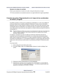
Page 1 of 21
GIS – TRANPLAN INTERFACE PROJECT
DOCUMENTATION
MAPINFO GEOGRAPHIC INFORMATION SYSTEM
DEVELOPED BY:
Center for Transportation Research and Education
IOWA STATE UNIVERSITY
SPONSORED BY:
IOWA DEPARTMENT OF TRANSPORTATION
Page 2 of 21
TABLE OF CONTENTS:
1.
Introduction and Overview
1.1. Program Objectives
1.2. Questions Concerning the Interface
1.3. Definitions
3
2.
How to Use this Manual
5
3.
Getting Started
3.1. Setting Up Folder Structure
3.2. Downloading & Installing the Software
3.3. Opening the ArcView Project
3.4. Files Needed to get Started
6
4.
Creating a Tranplan Network – “Registering”
8
5.
Running Tranplan From MapInfo – “Modeling”
5.1. Tranplan Model Run – “Model Run”
5.2. Tranplan Model Run – “Join a Model Run in Progress”
5.2.1. Run Netbld
5.2.2. Run Tranplan
5.2.3. Run Utilities
5.2.4. Run Loaded
5.2.5. Into MapInfo
13
6.
Index and References
21
Page 3 of 21
1.
INTRODUCTION AND OVERVIEW:
Welcome to the Iowa Department of Transportation’s MapInfo based GIS-Tranplan Interface program. The
program was designed to be useful as well as user-friendly. To assist you the user in becoming familiar and
comfortable with the interface program, we suggest you read through this user’s manual, and keep it handy
during the use of the programs. Other useful materials include a Tranplan and MapInfo user’s manual.
1.1
Program Objectives
The objective of this software is to provide a convenient method for transferring travel models and their data
between MapInfo and Tranplan. By automating formerly labor-intensive steps, the interface reduces user’s
computer time, improves file management, and assist in visualization of the traffic network data.
A key addition to the MapInfo-Tranplan Interface is the help-sensitive tool tips added to non-MapInfo input
windows. Through the use of Visual Basic programming, the user is given reference locations in either the
Tranplan manual or the interface user’s manual for information regarding required input.
1.2
Questions Concerning the Interface
Listed below are frequently asked questions and answers relating to the use and usefulness of the interface.
I have the Software, Where Do I Start? The section entitled How Do I Get Started, Page 7 of the
documentation, details the procedure of copying the required files into a program file directory named
TPMITools. Once this is done, a working directory should be created for each model scenario. After
placing all applicable data files (Table 1-1), along with the provided MapBasic program TpMiExt.mbx, into
the working directory, the user is ready to begin the process.
The Software is Installed, How do I Start the Process? To begin the modeling process, a network must
exist or be created. If the working directory has both a links data file and a nodes data file that are properly
formatted for Tranplan use (see figures 4-3 and 4-4 for examples), then by using the TP MI-“Registering”
pull-down menu option, the interface will begin the modeling process. See section 4. Creating a Tranplan
Network for more details
My Tranplan Network Data is Not Formatted Like the Example Files. Tranplan requires proper data
format. This formatting is of column delimited text form, which means that each column in the data file is
reserved for a certain data set. For example, columns one through five may be reserved for a node number.
Therefore, all numbers that are in columns one through five are considered to be part of the node number,
even if there happen to be letters, spaces, etc. in these columns. When Tranplan tries to read these
columns, an error will be generated when the data is incorrectly formatted. Therefore, references to the
Tranplan user’s manual are supplied to assist in the correct formatting of data.
I have the Network, now What Do I Do? By using the Modeling-“Model Run” pull-down menu, the
interface will begin the modeling process. After the user completes the input windows, the interface will
proceed through the modeling process. See section 5.1 for more details.
Do I want to let the Interface Create a Tranplan Control File? If you are required to use an existing
module for Tranplan, or you have a working knowledge of Tranplan and would like to write your own
module, then select no.
Can I Use a Different Traffic Assignment Method? If you are familiar with Tranplan control files, you
may want to use a traffic assignment method other than the equilibrium method used in the default control
file. To do this, select No when prompted if you would like the interface to create a Tranplan control file.
When prompted if you would like the interface to run Tranplan, choose Yes. Finally, the interface will
prompt for which control file to use. Select the user created option and enter your control file’s name.
There is a New Table Called Ld_links.tab. What happens next? The Ld_links.tab table is the same visual
layer as the links.tab file. However, the Ld_links.tab table contains the output from Tranplan, known as the
loaded network. This loaded network contains the speeds and capacities that make up the model when all
Page 4 of 21
trips have been generated and distributed. The creation of Ld_links.tab is the last step of the modeling
process.
I’ve Made a Mistake, Can I Go Back? Yes, by using the Modeling-“Join a Model Run in Progress” pulldown menu tool, the interface allows you to go back to any part of the modeling process and repeat the
entire procedure from the point where the interface program is returned to. Section 5.2 describes the Join a
Model Run in Progress options.
1.3
Definitions
Listed below is a set of terms that help describe the workings of the interface.
Loaded Network – The output from Tranplan that includes the speeds and capacities on the links in the
network when the trip assignment has been completed. This network is identical in graphical
appearance to the unloaded, or original network. However, the links in the network have had the
Tranplan data added into the original data.
Model – Included in a model is the scenario’s network, along with all data that is used to assist the user
in making decision concerning the scenario.
Network - Defined by the Tranplan user’s manual as: A description of the network in terms of “nodes”
and “links”. Nodes define a given point of physical location within the study area. Each node must
have a unique number, and if plotting or graphic display is desired, each node must be assigned an
(x,y) coordinate pair. Links define a section of roadway or transit right-of-way between two nodes,
and the attributes such as speed and capacity, that are to be associated with the link.
Scenario - As part of the program package, this interface allows the user to have multiple models
running at one time. In addition, the same basic project can be opened and edited without having to
close the original project. Therefore, each version of the interface that is running is called a
scenario. These scenarios may be completely separate models, identical models with minor editing
to the network, or exactly the same network. By setting each scenario in a unique working directory,
no data sharing issues should arise.
Traffic Analysis Zone (TAZ) - A designated area where productions and attractions have been
assigned for use in the scenario’s model. For input in the interface, the number of TAZ’s includes
both the internal and external TAZ’s.
Turn Penalty - A value assigned to a turning movement that begins at the origin or A node, goes
through the turning or B node, and terminates at the destination or C node. This value represents the
number of minutes a turning vehicle must wait before making the turn, divided by 100. For
example, a value of 70 would indicate that a turning vehicle must wait 0.70 minutes before an
adequate gap in oncoming traffic occurs, allowing the vehicle to execute the desired turning
movement. This value is part of a turn file, described in the Default Module Builder section of this
manual. For more information see also the Tranplan user’s manual in the Loading section, page 411.
Turn Prohibitor - A line of data that indicates that a particular turning movement cannot be performed.
The syntax is similar to that of a turn penalty file, however, no value is entered in the last column.
This file is described in more detail in the Arcnet section of this manual. For more information see
also the Tranplan user’s manual in the Network section, page 1-9.
Page 5 of 21
2.
HOW TO USE THIS MANUAL:
As you work through the GIS-Tranplan Interface, there is a sequence of events that must be carried out in order for the
process to be successful. Below is a flowchart that shows the required sequence for carrying out a model run. Each
process in the flowchart has a chapter associated with it. By identifying the process on the flowchart, then finding the
corresponding chapter in this user’s manual, the user can review an in-depth discussion on each segment of the interface
program.
Font Descriptions: This manual uses different font styles to indicate that the phrase in question belongs in a distinct
descriptive category.
Italics – Indicates that the phrase is the name of a file used by the interface.
Bold – Indicates that the phrase is the title of an input box located on an input window in the interface program.
“Italic Quotes” – Indicates the name of a pull-down menu option.
Page 6 of 21
3.
Getting Started:
3.1
Setting Up the Directory Structure
Using the interface requires a directory to store the data files for each model scenario and second directory to store the
Visual Basic executables and other files needed to run the interface. For the directory in which the Visual Basic
programs are stored, it is recommended that the folder be on the computer’s hard drive and named “C:\TPMItools”. It is
not necessary that this folder be stored on the hard drive or use the recommended name as it is possible to specify a
unique path each time the MapBasic program is opened. For the data directory, keeping the path under thirty characters
will allow MapInfo to execute the Tranplan model run. If the path name exceeds thirty characters, then one must
complete the Tranplan run manually.
3.2
Downloading & Installing the Software
One version of the Tranplan-MapInfo interface is available; it interacts with both Tranplan 8.0 and Tranplan 9.0. This
download contains a self-extracting zip file that will expand the Visual Basic programs and install several DLL files onto
the computer’s hard drive. To download the software, go to the project’s homepage at
http://www.ctre.iastate.edu/Projects/tp_is/Enhance/Web/download.html.
After the self-extracting zip file has been saved, follow the instructions below to install the programs.
1.
2.
Click on the link.
Choose the option SAVE FILE. It is recommended that the self-extracting zip file be saved to a temporary
directory (i.e., C:\temp).
3. Double click on the self-extracting zip file.
4. If not already the default, set the extraction location to the same folder of the self-extracting zip file.
5. Press (“EXTRACT” or “UNZIP”).
6. After all files have been extracted, double click on “Setup.exe”. Carefully read and follow the instructions on
each help screen. Note that the default location where the program is going to be installed at. It is suggested
that this default location be changed to a recognizable folder on the local drive (i.e., C:\TPMITools).
7. After completing Setup.exe, all the needed files are stored in a single directory, including the provided MapInfo
program, TpMiExt.mbx, along with a data folder containing all required files to run a demo model.
8. Place a copy of the MapBasic program, TpMiExt.mbx in each model scenario’s working directory.
3.3
Opening the MapBasic Program
Once all data files and the TpMiExt.mbx file are placed in the working directory, start MapInfo and then run the program
TpMiExt.mbx. The TpMiExt.mbx project is the working MapBasic program for the interface. The interface will cause
MapInfo to add a new pull-down menu option. Figure 3-1 shows the MapInfo toolbar after opening TpMiExt.mbx. Also
upon opening the MapBasic program, three prompts will appear to verify the MapInfo working directory, Tranplan
directory, and the Visual Basic tools directory.
Figure 3-1 MapInfo Enhanced Pull-Down Menu
Page 7 of 21
3.4
Files Needed to get Started
If a Tranplan network already exists in ASCII text format, then a copy of several different files should be placed in the
model scenario’s working directory along with the MapBasic program, TpMiExt.mbx. A list and description of the
required data files is located in Table 1-1.
Table 3 – 1 Required Data Files
File Name
TpMiExt.mbx
Ext. dat
Friction.dat
File Description
MapBasic program containing the Tranplan interface.
External data file for Default Module Builder, see Figure 5-10.
Friction data file for Default Module Builder, see Tranplan user’s
manual, Models section, page 1-7, or Figure 5-11.
Gm.pa
Gravity Model Production/Attraction File for Network Data
User Input form, see Figure 4-9 C
Pro.txt
Production file C
Att.txt
Attraction file C
Links.dat
Links data file for Network Data User Input form, see Figure 4-8.
Nodes.dat
Nodes data file for Network Data User Input form, see
Figure 4-7 B
Turn.txt
Turn prohibitor only file for Arcnet, see Figure 5-6. A
Turnpenpro.txt Turn penalty/prohibitor file for Default Module Builder, see
Figure 5-9. A
A. The scenario’s network may not have any prohibited turns; therefore, it is possible to omit these files.
B. Required only if using Network Data User Input form. New Network requires only links.dat.
C. A production/attraction file is required, however, the productions and attractions may be in separate files,
then merged during the interface’s process. The maximum number of trip purposes allowed by the
interface is ten, however, only one purpose is required.
Page 8 of 21
4.
CREATING A TRANPLAN NETWORK – “REGISTERING”
Description: The Network Data User Input form allows the user to convert text files containing node and link data into
mappable MapInfo files. The input files must be in Tranplan format, and the number of TAZ’s must include both the
internal centroids and the external stations.
Quick Instructions:
1. Select the menu option TP MI-“Registering”
2. Fill in the text boxes in the window titled “Network Data User Input”, TP_MI.exe.
A. Change in the name of the nodes data file if the default is incorrect.
B. Change in the name of the links data file if the default is incorrect.
C. Change in the name of the production and attraction data file if the default is incorrect.
• If the production and attraction data are in separate files, click MERGE (Figure 4-3).
• Use the BROWSE button to enter the name of the production data file.
• Use the BROWSE button to enter the name of the attractions data file.
• Click ENTER, will create production and attractions file called combgm.pa.
D. Enter the number of TAZs, including the external stations.
E. Change the X and Y coordinate conversion factors if other than one.
F. Choose the Tranplan coordinate system used for the nodes data file.
G. Press OK.
3. Press YES if Network Data User Input executes properly.
4. Several status boxes will appear, click OK to continue.
Input (User): The Network Data User Input form (see Figure 4-1) prompts the user to input both data and network data
files. The first input (Input the name of the nodes file) prompts the user to identify the data file containing the nodes
data for the particular scenario that the user opened the ArcView project in. A default file name, nodes.dat, is given in
the file name box, and a browse button allows the user to search for the file if the given default name is incorrect. The
same procedure is used for identifying both the links data file (Input the name of the links file), default value of
links.dat, and the productions and attractions file (Input the name of the productions and attractions file), default
value of gm.pa for the network. If the production and attraction data is stored as separate files, use the merge function,
see Figure 4-2, to combine the two files into combgm.pa. The fourth user input box is for inputting the number of
Transportation Analysis Zones (TAZs) (Input the number of TAZs and external stations). This number is to include
both the interior and exterior zones for the particular project scenario. No default is given, therefore the user should have
some working knowledge of the project scenario network. The value entered in this box will become the default value
for succeeding programs, so care in entering the correct value should be taken here. Next are the input boxes that ask for
the coordinate conversion factors. The input box on the left of the input window, labeled the (Input the x coordinate
conversion factor) allows the user to alter the physical size of the network by scaling the entire network in the x
direction. The default value for the x coordinate factor, 1, is given. The input box on the right, (Input the y coordinate
conversion factor; 1), allows for the same type of scaling in the y direction. The final input box (Choose the proper
Tranplan coordinate system) allows the user to decide whether the network scenario’s coordinates are stored in large
or small coordinates. Tranplan stores the coordinate data in either a five digit or nine digit variable, therefore, selecting
the incorrect coordinate system will cause a system error of this interface.
Page 9 of 21
Figure 4-1 Network Data User Input Form
Figure 4-2 Production/Attraction Merger Form
Below is a sample of how each of the input files should be formatted (see Figures 4-3 through 4-5). Tranplan demands
data is formatted so as to exist in a particular column, or range of columns. Consult the Tranplan user’s manual for more
information on input data formatting.
Page 10 of 21
Figure 4-3 Nodes.dat Example
See the Tranplan User’s Manual, Networks section, page 1-9 (large coordinates) for more details on proper formatting.
Figure 4-4 Links.dat Example
See the Tranplan User’s Manual, Networks section, page 1-11 for more details on proper formatting.
Figure 4-5 Gm.pa (Gravity Model Production/Attraction) Example
See the Tranplan User’s Manual, Models section, page 1-8 for more details on proper formatting.
Please note that this interface requires the use of no more than ten productions or attractions. If fewer than ten
productions or attractions exist, the Interface will fill remaining production and attraction columns with zeros to produce
exactly ten productions and ten attractions. The new file will be named Newgm.pa, and should be used whenever a
production/attraction file is required by the Interface. See the Tranplan user’s manual, Model section, page 1-7 for more
details.
Input (Default): The Network Data User Input form requires that the directory tree file, dirtree.txt, contain the file name
of the working directory. The working directory needs to contain all data files, and will be the destination of all output
files created. Shown below is an example of a directory tree file (Figure 4-6).
Figure 4-6 Directory Tree File Example
Page 11 of 21
Output: The Network Data User Input form produces both hidden and visible file outputs. The visible files are the
nodesout.dat file (Figure 4-7) and linksout.dat file (Figure 4-8). These files, which are written into the default
working directory of the current project scenario, are used by MapInfo to create tables of both the nodes and links
that make up the scenario’s network. The hidden file that is created holds the number of TAZ’s that were input into
the program by the user. This file, also stored in the default directory, is taz.txt (Figure 4-9). Below are examples of
the output files from the Network Data User Input form.
Figure 4-7 Nodesout.dat Example
Figure 4-8 Linksout.dat Example
Figure 4-9 Taz.txt Example
Once the Network Data User Input form is completed, the program will ask the user whether to continue or not. By
selecting Yes, the interface will continue creating the scenario’s network. Selecting No will terminate the progress of the
interface, but will not delete any data, or prohibit any future usefulness of the interface to the scenario. The program will
then convert the output files into tables. Both the nodes and links files are converted, and are named nodes.tab and
links.tab respectively. Figure 4-10 shows an example of a nodes.tab table, while Figure 4-11 shows links.tab. Finally,
the tables are loaded into the Network map screen, similar to Figure 4-12.
Page 12 of 21
Figure 4-10 Portion of Nodes.tab Example
Figure 4-11 Portion of Links.tab Example
Figure 4-12 Network Map Screen
Page 13 of 21
5.
Running Tranplan From MapInfo – “Modeling”
Once a network has been created in MapInfo, the Tranplan modeling software can be utilized to create a loaded network.
The pull-down menu, “Modeling”, has two new options for the user. The first option, “Model Run”, allows the user to
take advantage of the interface’s programming to create all necessary files for the Tranplan modeling process. All file
loading has been automated, providing a streamlined modeling process. The second option, “Join a Model Run in
Progress”, allows the user to return to a previously completed process in the Model Run, and repeat the remainder of the
modeling process. The remaining options are FORTRAN based programs that had been created for a previous interface.
An example of the Modeling pull-down menu options can be found below in Figure 5-1.
Figure 5-1
5.1
Tranplan Model Run – “Model Run”
Description: The “Model Run” options allows the user to easily execute Tranplan, and display the output in MapInfo.
This is accomplished through the use of five steps.
1.
2.
3.
4.
5.
Run Netbld
Run Tranplan
Run Utilities
Run Loaded
Into MapInfo
These five steps can also be carried out through the use of the “Join a Model Run in Progress” pull-down menu option.
Selecting “Model Run” begins the modeling process with step one and continues through step five. By selecting “Join a
Model Run” the user can pick a step that needs to be repeated. Any one of the five steps of the modeling process can be
selected, with the modeling process being continued from there. The procedures for completing the entire “Model Run”
are identical to the steps required for completing all the “Join a Model Run” steps, therefore see the section of Tranplan
Model Run – “Join a Model Run in Progress” for more details.
Quick Instructions:
1. Select the Modeling-“Model Run” pull-down menu option.
2. Enter into Mapnet the number of TAZ’s and whether the model includes a turn prohibitor file. If the
model does include a turn prohibitor, select yes, then enter the name of the turn prohibitor file in the
turn prohibitor file name input form.
3. Select Yes if the interface is to write the Tranplan control files. If No, go to step six.
4. Select the Default Tranplan control file option, and press OK.
5. Enter the required input into the Default Module Builder.
6. Select Yes if the interface is to run Tranplan. If No, go to step nine.
7. Select the Default Tranplan control file, unless a user-designed Tranplan control file exists and is
preferred.
8. After Tranplan is completed the model run, type EXIT in the DOS window, or simply close the DOS
window.
9. Input the required file names and options into Netcard as shown in Figure 5-13, then close the DOS
window.
Page 14 of 21
10. Enter the name of the Netcard output file into the Map_Load User Input form and press Continue. A
ld_links.tab and ld_links map will be created.
5.2
Tranplan Model Run – “Join a Model Run in Progress”
Description: The “Join a Model Run in Progress” option of the Modeling pull-down menu allows the user to return to
one of the six modeling steps as listed in the Tranplan Model Run – “Model Run” section of this manual. In the event
that one of the six steps in the modeling process was unsuccessful, the user can select the “Join a Model Run in
Progress” option. This option displays a list of options, see Figure 5-2, to specify the step that requires repeating.
Figure 5-2
5.2.1 Run Netbld
Description: Once a network has been built in MapInfo, including both the tables (see Figures 4-10 & 11), and the visual
data in a map (see Figure 4-12), the Tranplan model run can begin. Then the Tranplan control file for operating the Build
Highway Network module is written by Mapnet. The second input screen is the Default Module Builder. The
instructions for the Default Module Builder begin on page 16.
Quick Instructions: Begin on step two of quick instructions in the Tranplan Model Run – “Model Run” section.
Mapnet
Input (User): Mapnet’s input window (see Figure 5-3) calls for both the number of TAZ’s and for the existence of a turn
prohibitor file. The TAZ input box (Please input the number of TAZ’s that are a part of this model) has listed as the
default the value from TAZ.txt (Figure 4-9). The turn prohibitor input box (Does this model include a turn prohibitor)
lists the choices of No or Yes. The default is No, so in the event of no input, the program assumes that no turn prohibitor
file exists. By selecting Yes, then hitting Continue, a second input window will appear prompting the user for the name
of the turn prohibitor file name. A browse button is provided to allow navigation to the required file. Once the turn
prohibitor file (Figure 5-4) is located, pressing Continue executes the program, or Cancel returns the original Mapnet
input window.
Page 15 of 21
Figure 5-3 Mapnet Input Window
Figure 5-4 Turn Prohibitor File, turn.txt Example
See the Tranplan user’s manual, Networks section, page 1-10 for more details.
Input (Default): Mapnet requires that several files exist that are not input by the user. Without the required default files,
the program will not operate. The first default file is the directory tree file, dirtree.txt, described in the Tranplan Text
Network -“Registering” section of this manual (Figure 4-6). This file contains the name of the working directory. This
directory contains all the input, and will receive all the output. The next required file is taz.txt, which is described in
Tranplan Text Network – “Registering” also (Figure 4-10). It contains the user’s previously entered value for the
number of TAZ’s in the scenario’s network. Finally, nodesout.dat (Figure 4-7) and linksout.dat (Figure 4-8) are the two
final default inputs for running Mapnet.
Output: Mapnet produces a text file, net-in.txt, which is used as a control file when running Tranplan. This control file
is created exclusively for the project scenario that is being worked on. The module that Tranplan will execute when netin.txt is run is the Build Highway Network module. The output file that Tranplan will create when executing net-in.txt is
net.bin.
Default Module Builder
Description: The interface provides the user with the option to use a default Tranplan control file that is written
specifically for the current scenario. By selecting Yes when prompted to use a Visual Basic control file (Figure 5-5), the
Default Module Builder program is utilized. Default Module Builder (Figure 5-6) writes a text file that is used as the
control file for Tranplan. This control file ensures the user that all1 required output files from Tranplan will be created
when performing a model run.
Quick Instructions: Begin on step three of quick instructions in the Tranplan Model Run – “Model Run” section.
Page 16 of 21
Figure 5-5
Input (User): Default Module Builder (see Figure 5-6) requires the user input of two file names and three variables. The
first input box (Input the Turn Penalty/Prohibitor File, or Hit Continue if No Turn Restrictions Exist) requires the
turn penalty/prohibitor file (see Figure 5-9 for an example file). Hitting Continue or not selecting a file indicates that no
turn penalties or turn prohibitors exist in the scenario’s model. The next input box (Input the Total Number of TAZs)
will contain the default value found in TAZ.txt (Figure 4-13) for the scenario. The following two boxes (Input the First
External Zone Number and Input the Last External Zone Number) prompt the user to indicate the range of numbers
that contain the external nodes of the scenario’s network. The input box (Input the Name of the Trip Survey Data
File) requires the user to input the external nodes trip data file for the scenario’s model. The default file given is ext.dat
(see Figure 5-10). The next input box (Input the Name of the Network Friction File) requires the network friction
data (see Figure 5-11). The final input box (Input the Name of the Production/Attraction File) prompts the user to
input the name of the Network Data User Input form’s newly created production/attraction file, newgm.pa.
Figure 5-7 Turnpenpro.txt Example
For more details, see the Tranplan user’s manual, Loading
section, page 4-12.
Figure 5-6 Default Module Builder Input Window
Page 17 of 21
Figure 5-8 Ext.dat Example
This data must be formatted according to the Simple
format described in the Tranplan User’s Manual, Matrix
Utilities section, page 6-4.
Figure 5-9 Friction.dat Example
For more details, see the Tranplan User’s Manual, Models
section, page 1-8.
Input (Default): The Default Module Builder program uses the same default files as the previously documented
programs. These include the dirtree.txt file and taz.txt file (see Figures 4-6 and 4-9 respectively); along with the
nodesout.dat file (see Figure 4-10). Also required in the output of the Mapnet control file builder, net-in.txt.
Output: Only one file is produce from the Default Module Builder, and similar to Mapnet, this is a text file that is
used as a control file for running Tranplan. Called default.in (see Figure 5-10 for a portion of default.in), this
control file will create the necessary data files for running the analysis tools associated with the Interface. The
modules that Default Module Builder uses as part of its control file include: Highway Selected Summation, Build
Intrazonal Impedances, Matrix Update, Gravity Model, Build Trip Table, Matrix Manipulate, Matrix Transpose,
Equilibrium Highway Load and Report Matrix.
Figure 5-10 Sample of Default.in
Page 18 of 21
5.2.2 Run Tranplan
Description: The interface gives the user the option to run Tranplan from MapInfo. Selecting Yes to Would you like
the interface to run Tranplan? (Figure 5-11) prompts the user to select which control file for Tranplan to execute.
Selecting No sends the interface to step three (Run Netcard.exe). When a control file has been specified, the interface
copies the control file into the Tranplan directory, and writes a DOS batch file to execute Tranplan. The copied control
file is renamed to the default value of trnpln.in, overwriting any previous Tranplan model runs. The batch file is stored
in the scenario’s working directory, and is named tprun.bat (Figure 5-12). Tprun.bat first navigates to the Tranplan
directory, then executes trnplnxt.exe. This Tranplan program creates a second batch file, which is stored in the Tranplan
directory. This second batch file, trnplnx.bat, gives directions on running the control file, trnpln.in. The last command
in tprun.bat executes the newly created batch file trnplnx.bat, which caused Tranplan to execute the model run. Once
Tranplan has completed the model run, the output file trnpln.out is copied to the scenario’s working directory and
renamed to the original input file’s filename, but with .out as an file extension. Note: The Tranplan DOS window
must be closed manually.
Quick Instructions: Begin on step six of quick instructions in the Tranplan Model Run – “Model Run” section.
Figure 5-11
Figure 5-12 Tprun.bat
Input (User): The first required input from the user is whether or not to run Tranplan through the interface. If the user
chooses to allow the interface to operate Tranplan, then the second input is to select which control file(s) to be used with
Tranplan. The user may either choose to use the default control file created in the Write a Tranplan Control File section
of this chapter, or choose to use previously written control file(s) for the scenario. The filename and location of
previously written control files must then be specified if the default control file is not selected.
Output: A completed Tranplan model run results in an output file called trnpln.out, which is copied to the working
directory and renamed default.out. Also created as part of the model run are the network file containing the loaded
traffic volumes, called out.bin, and the origin-destination matrix file, tot90x.trp.
5.2.3 Run Utilities
Description: By selecting the “Run Utilities” option, the interface calls Netcard.exe. Netcard is a Tranplan program that
converts the binary files used by Tranplan to text files in Tranplan format. Figure 5-13 shows Netcard.exe, including
defaults to the required inputs.
Page 19 of 21
Figure 5-13 Netcard Example
Quick Instructions: Begin on step nine of quick instructions in the Tranplan Model Run – “Model Run” section.
Input (User): The critical input statement for Netcard.exe is Enter input file name. This file is the binary file created
during the Tranplan model run. During this stage of the interface, the required binary file contains the loaded traffic
volumes, along with either the speeds or times, on each network link. The default values for the remaining input
statements are shown in Figure 5-13.
Output: Netcard.exe produces a text file containing the loaded network. This file is Tranplan formatted, and contains
nodes, turn prohibitors, and the loaded links for the scenario’s network. An example of the Netcard output is shown in
Figure 5-15.
5.2.4 Run Loaded
Description: The “Run Loaded” option converts Tranplan formatted Netcard output into MapInfo tables. The interface
uses the Map_Load form (Figure 5-14) to make the data conversion. Map_Load creates an updated table to display the
Tranplan output in the interface. The output from Netcard is joined with the original linksout.dat file to create a loaded
links file called ld_links.tab. This new file contains both the actual counted volumes and the applied Tranplan volumes
for each link, along with a percent difference column for analysis purposes.
Quick Instructions: Begin on step ten of quick instructions in the Tranplan Model Run – “Model Run” section.
Input (User): The user is prompted to input the name of the output file from Netcard (Input the name of the ASCII text
file from the Tranplan Run). The default name is out.dat, however, the file name must be identical to the output name
specified in Netcard. The input window can be found in Figure 5-16. A sample of out.dat is pictured in Figure 5-17.
Input (Default): Map_Load requires that the directory tree file (see Figure 4-6) and the linksout.dat file (see Figure 4-8)
are present in the scenario’s working directory.
Output: Map_Load creates a new table containing the loaded volumes for the scenario’s network. All pertinent
information that Tranplan produces about scenario’s network links is written into the new table. This table is called
ld_links.tab, and is used to create a map in MapInfo. See Figure 5-16 for a ld_links.tab file example.
Figure 5-14 Map_Load Input Window
Page 20 of 21
Figure 5-15 out.dat
Figure 5-16 Portion of Ld_links.tab Example
5.2.5
Into MapInfo
At this point, MapInfo displays ld_links.tab in the Ld_links map. This is the last step in loading the scenario’s network.
All coordinates, ground counts, and Tranplan output are accessible by browsing through the ld_links.tab table. Figure 517 shows the Ld_links map containing the ld_links.tab file. Analysis of the scenario’s network can now be done through
the use of previously built analysis tools.
Figure 5-19 Interface with the Loaded Network
Page 21 of 21
6.
INDEX AND REFERENCES:
Batch files
model run batch file (tprun.bat)
shortest path batch file (sprun.bat)
24, 32
32
Directory Tree (dirtree.txt)
10
Example data
External data (ext.dat)
7
7, 16, 17
Friction data (friction.dat)
7, 17
Links data
MapInfo input (linksout.dat)
MapInfo maps
original data (links.dat)
Loaded links data
11
12
8, 10
20
MapBasic program (TpMiExt.mbx)
Mapnet
3, 6, 7
13-15
Netcard
18, 19
Network data (out.dat)
19, 20
Nodes data
MapInfo input (nodesout.dat)
MapInfo maps
original data (nodes.dat)
11
12
8, 10
Production/attraction data
attraction file only (att.txt)
combined by interface (combgm.pa)
reformatted by interface (newgm.pa)
original data (gm.pa)
production file only (pro.txt)
7
8
10, 16
7, 8, 10
7
Setup.exe
6
Traffic Analysis Zone (Taz.txt)
Tranplan control files (default.in)
Turn penalty/prohibitor file (turnpenpro.txt)
Turn prohibitor file (turn.txt)
11, 14-17
17
7, 16
7, 15
Tranplan User’s Manual, URBAN/SYS, version 9.0, Urban Analysis Group, Inc., Danville, California, Copyright
1988-1998