1
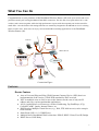
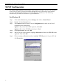
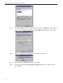
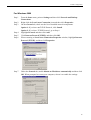
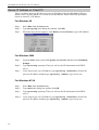
Broadband Wireless Router (Access Point)
User Manual
Note
No part of this publication may be reproduced in any form by any means without the prior written
permission. Other trademarks or brand names mentioned herein are trademarks or registered
trademarks of their respective companies.
March 2002, Rev02
Safety Instructions
Installing
Use only the type of power source indicated on the marking labels.
Use only the power adapter supplied with the product.
Do not overload wall outlet or extension cords as this may increase the risk of electric
shock or file, If the power cord is frayed, replace it with a new one.
Proper ventilation is necessary to prevent the product overheating. Do not block or
cover the slots and openings on the device, which are intended for ventilation and
proper operation. It is recommended to mount the product with a stack.
Do not place the product near any source of heat or expose it to direct sunshine.
Do not expose the product to moisture. Never spill any liquid on the product.
Do not attempt to connect with any computer accessory or electronic product without
instructions from qualified service personnel. This may result in risk of electronic
shock or file.
Do not place this product on an unstable stand or table.
Using
Power off and unplug this product from the wall outlet when it is not in use or before
cleaning. Pay attention to the temperature of the power adapter. The temperature might
be high.
After powering off the product, power on the product at least 15 seconds later.
Do not block the ventilating openings of this product.
When the product is expected to be not in use for a period of time, unplug the power
cord of the product to prevent it from the damage of storm or sudden increases in
rating.
Servicing
Do not attempt to disassemble or open covers of this unit yourself. Nor should you attempt to
service the product yourself, which may void the user’s authority to operate it. Please call
vendor under the following conditions:
If the power cord or plug is damaged or frayed.
If liquid has been spilled into the product.
If the product has been exposed to rain or water.
If the product does not operate normally when the operating instructions are followed.
If the product has been dropped or the cabinet has been damaged.
If the product exhibits a distinct change in performance.
2
DISCLAIMER OF WARRANTIES AND LIABILITY
KOBIAN OR THE AUTHORIZED RESELLERS OR THE DISTRIBUTORS
SHALL NOT BE RESPONSIBLE FOR ANY LOSS OR DAMAGE TO COMPANY,
ITS CUSTOMERS, OR ANY THIRD PARTIES FOR ANY REASON
WHATSOEVER, AND MAKES NO WARRANTY OR REPRESENTATION,
EXPRESSED, IMPLIED, OR STATUTORY, WITH RESPECT TO ITS
PRODUCTS OR THE CONTENTS OR USE OF THIS DOCUMENTATION AND
ALL ACCOMPANYING SOFTWARE, AND SPECIFICALLY DISCLAIMS ITS
QUALITY, PERFORMANCE, MERCHANTABILITY, OR FITNESS FOR ANY
PARTICULAR PURPOSE.
KOBIAN OR THE AUTHORIZED RESELLERS OR THE DISTRIBUTORS
SHALL NOT BE LIABLE FOR ANY ACTUAL, DIRECT, INDIRECT, SPECIAL,
PUNITIVE, INCIDENTAL, OR CONSEQUENTIAL DAMAGE (INCLUDING, BUT
NOT LIMITED TO, PROCUREMENT OF SUBSTITUTE GOODS OR SERVICES;
LOSS OF USE, DATA, OR PROFITS; OR BUSINESS INTERRUPTION)
HOWEVER CAUSED, WHETHER IN CONTRACT, STRICT OR OTHER LEGAL
THEORY OF LIABILITY, OR TORT (INCLUDING NEGLIGENCE OR
OTHERWISE) ARISING IN ANY WAY OUT OF THE USE OF THIS PRODUCT
AND SOFTWARE, EVEN IF ADVISED OF THE POSSIBILITY OF SUCH
DAMAGE.
KOBIAN OR THE AUTHORIZED RESELLERS OR THE DISTRIBUTORS
RESERVES THE RIGHT TO REVISE OR UPDATE ITS PRODUCTS,
SOFTWARE, OR DOCUMENTATION WITHOUT OBLIGATION TO NOTIFY
ANY INDIVIDUAL OR ENTITY.
KOBIAN OR THE AUTHORIZED RESELLERS OR THE DISTRIBUTORS
SHALL NOT BE RESPONSIBLE FOR ANY INCORRECT SETTING OF
OPERATING CHANNELS IN COMPLIANCE WITH THE REGULATORY
STANDARDS OF INDIVIDUAL COUNTRY. USERS SHOULD SET THE
CORRECT OPERATING CHANNELS ACCORDING TO THE REGULATORY
STANDARDS OF THEIR COUNTRY. REFER TO “NOTE FOR OPERATING
CHANNELS” FOR MORE INFORMATION
Copyright Notice
© Copyright 2001-2003, Kobian Group
All rights reserved.
All trademarks and/or registered trademarks are properties of their respective owners.
Contents
SAFETY INSTRUCTIONS................................................................................................................... 2
Installing........................................................................................................................................... 2
Using ................................................................................................................................................ 2
Servicing........................................................................................................................................... 2
CONTENTS............................................................................................................................................ 3
WHAT YOU CAN DO ........................................................................................................................... 7
FEATURES .............................................................................................................................................. 7
Router Feature .................................................................................................................................. 7
Bridging Features ............................................................................................................................. 8
Wireless LAN Features .................................................................................................................... 8
SYSTEM REQUIREMENTS ....................................................................................................................... 8
For Wireless Clients ......................................................................................................................... 8
For Ethernet (wired) Clients............................................................................................................. 8
UNPACKING YOUR BROADBAND WIRELESS ROUTER (AP) ................................................................... 9
INDICATORS AND CONNECTING ................................................................................................ 10
FRONT PANEL ...................................................................................................................................... 10
REAR PANEL ........................................................................................................................................ 10
CONNECTING THE BROADBAND WIRELESS ROUTER (AP)................................................................... 11
1 Connecting to the WAN port. ..................................................................................................... 11
2 Connecting to the LAN port L1/L2/L3/L4. ................................................................................ 11
3 Preparing your wireless station................................................................................................... 11
4 Connecting the power adapter..................................................................................................... 11
BASIC CONFIGURATION ................................................................................................................ 12
ON ETHERNET CLIENT ........................................................................................................................ 12
ON WIRELESS CLIENT ......................................................................................................................... 12
XDSL/ATU-R CONNECTION ........................................................................................................... 14
Connecting to Your xDSL Modem ................................................................................................ 14
Connecting to Your ATU-R............................................................................................................ 15
TCP/IP CONFIGURATION ............................................................................................................... 16
For Windows 98 ............................................................................................................................. 16
For Windows NT............................................................................................................................ 17
For Windows 2000 ......................................................................................................................... 19
RENEW IP ADDRESS ON CLIENT PC .................................................................................................... 20
3
Broadband Wireless Router (AP) User Manual
For Windows 98 ............................................................................................................................. 20
For Windows 2000 ......................................................................................................................... 20
For Windows NT4.0....................................................................................................................... 20
WEB CONFIGURATION OVERVIEW ........................................................................................... 21
Using the Web-Based Manager...................................................................................................... 21
Outline of Web Manager ................................................................................................................ 21
To Have the New Settings Take Effect........................................................................................... 21
BASIC CONFIGURATION ................................................................................................................ 23
WAN SETTING .................................................................................................................................... 23
PPPoE............................................................................................................................................. 23
Obtain an IP address automatically................................................................................................ 24
Specify an IP Address .................................................................................................................... 24
Bridge ............................................................................................................................................. 25
WIRELESS SETTING ............................................................................................................................. 26
ADVANCED CONFIGURATION...................................................................................................... 27
LAN SETTING ..................................................................................................................................... 27
WEP SETTING ..................................................................................................................................... 29
Privacy Security ............................................................................................................................. 29
ROUTING ............................................................................................................................................. 30
IP Dynamic Routing....................................................................................................................... 30
IP Static Routing ............................................................................................................................ 31
FORWARDING ...................................................................................................................................... 32
DMZ ................................................................................................................................................... 33
UPNP .................................................................................................................................................. 33
QOS.................................................................................................................................................... 34
SYSTEM ............................................................................................................................................... 35
MANAGEMENT .................................................................................................................................... 35
Security........................................................................................................................................... 35
Save ................................................................................................................................................ 35
Upgrade .......................................................................................................................................... 36
Reset ............................................................................................................................................... 37
STATUS ................................................................................................................................................ 38
LOG ..................................................................................................................................................... 38
GLOSSARY .......................................................................................................................................... 39
TROUBLESHOOTING ...................................................................................................................... 42
PROBLEMS WITH LAN......................................................................................................................... 42
4
Contents
On Ethernet client........................................................................................................................... 42
On Wireless client .......................................................................................................................... 42
PROBLEMS WITH WAN........................................................................................................................ 42
PROBLEMS WITH UPGRADING.............................................................................................................. 43
PROBLEMS WITH DATE AND TIME ....................................................................................................... 44
SPECIFICATIONS .............................................................................................................................. 45
Wireless LAN Features .................................................................................................................. 45
Routing Features ............................................................................................................................ 45
Bridging Features ........................................................................................................................... 46
Security Features ............................................................................................................................ 46
Configuration and Management..................................................................................................... 46
Interface Specification.................................................................................................................... 46
Electromagnetic Compliance ......................................................................................................... 46
Power Adapter and Environmental Requirement........................................................................... 47
Physical .......................................................................................................................................... 47
5
What You Can Do
Congratulations on your purchase of this Broadband Wireless Router (AP) with 4-port switch and access
point that extend your existing broadband Cable/DSL connection. The 802.11b access point allows PC’s with
wireless cards connect together, while the high performance 4-port switch that expand your local network for
small office. Also the feature-rich routing functions are seamlessly integrated to broadband service for existing
home or office users. Now users can enjoy various bandwidth-consuming applications via the Broadband
Wireless Router (AP) .
Remote
WAN
xDSL/ATU-R
Internet
Connection Figure
Features
Router Feature
Acts as Universal Plug and Play (UPnP) Internet Gateway Device (IGD) that is an
implementation of the version 1 UPnP IGD standard for NAT traversal.
NAT let multiple users on LAN to access the Internet for the cost of only one IP
address and enjoy various multimedia applications.
ALGs (Application Level Gateways): such as NetMeeting, Ftp, RealPlayer, ICQ,
CuSeeMe, mIRC, Quake, Internet Games, etc.
DMZ hosting, Multiple Virtual Servers (e.g., Web, FTP, Mail servers) can be setup in
local network.
Static Route, RIP v1, v2, IGMP Proxy
Multiple kind of broadband WAN connection: PPPoE, DHCP Client, Fixed IP, Bridge
DHCP Server, DNS Relay
7
Broadband Wireless Router (AP) User Manual
Bridging Features
Supports self-learning bridge specified in IEEE 802.1D Transparent Bridging
Transparent Bridging between 4-port 10/100 Mb Ethernet switch and 802.11b Wireless
LAN interface
QoS Supports IEEE 802.1p tag for prioritize layer 2 traffic on 4-port Ethernet Switch
Port based priority that can prioritize specific port for multimedia streaming
applications
Security Features
PAP (RFC1334), CHAP (RFC1994) for PPPoE session
Wireless support WEP (Wired Equivalent Privacy) uses RC4 with 40/64 and 128 bit
key length
Support IP packets filtering based on IP address, Port number, Protocol type and TCP
code
Wireless LAN Features
Fully compatible to 802.11b standard, allowing up to 11Mbps wireless rate with
distance up to 300 feet / 90 meters
The 2.4 GHz Direct Sequence Spread Spectrum (DSSS) technology is exploited.
Seamless roaming within wireless LAN infrastructure
Low power consumption via efficient power management
Configuration and Management
Configurable through Web Browser
HTTP firmware upgrades via Web browser directly
Support DHCP Server function for IP distribution to local network users
QoS setting allows prioritizing one of 4 switch ports. The prioritized port could also be
changed
Event Logging, also provide different level of event display
System Requirements
For Wireless Clients
-
System OS (Windows 98/2000/NT/ME/XP)
Wireless card
Wireless card driver
For Ethernet (wired) Clients
System OS (Windows 98/2000/NT/ME/XP)
10/100Base-T NIC
10/100Base-T (UTP) network cable.
Hub
Note
xDSL/ATU-R service registered from your Internet service provider (ISP) is required
for Internet access.
8
What You Can Do
Unpacking Your Broadband Wireless Router (AP)
Check the contents of the package against the pack contents checklist below. If any of the
items is missing, please contact your ISP.
•
•
•
•
Broadband Wireless Router (AP)
Power Adapter
RJ-45 Ethernet Cable
Quick Started Guide and User Manual CD
9
Indicators and Connecting
Front panel
The following figure illustrates the front panel of the Broadband Wireless Router (AP):
1.
When link is established, the LED is On.
2.
When the device is transferring data, the LED is Blinking.
Rear Panel
The following figure illustrates the rear panel of your Broadband Wireless Router (AP).
PWR: Power Switch.
WAN: This RJ-45 10 Base-T port connects to an Ethernet port of xDSL/ATU-R
broadband device.
LAN port L1/L2/L3/L4: 10/100 Base-TX, 4 port auto-sensing & crossover Ethernet
switching hub (LAN interface).
12VDC: 12V power connector.
RST: Factory default reset switch.
To restore factory defaults, you do not need to power off the device. Push a small, stiff object
into the RST hole to press down the button. Keep pressing and wait fort 3 seconds (the DIAG
LED will illuminate about 3 seconds and turn off) to release the button. The device will
automatically restart. During restart, do not turn on/off the device and wait for the device to
boot up.
10
Indicators and Connecting
Connecting the Broadband Wireless Router (AP)
1 Connecting to the WAN port.
Connect the Ethernet cable with your xDSL/ATU-R to the 10Base-T Ethernet WAN port
on your Broadband Wireless Router (AP).
Note
1.
The attached xDSL/ATU-R must provide a standard 10Base-T Ethernet connection.
Please use the Ethernet cable comes with your broadband device or any other
standard 10Base-T Ethernet cable.
2.
The Ethernet cable supplied by your ISP for connecting to your xDSL/ATU-R may
be an Ethernet crossover or a straight-through cable. It is important to use the cable
provided by your ISP to connect the modem to your Broadband Wireless Router
(AP).
2 Connecting to the LAN port L1/L2/L3/L4.
Attach one end of the Ethernet cable with RJ-45 connector to the LAN port of your
Broadband Wireless Router (AP).
The Broadband Wireless Router (AP) incorporates a four-port switch for connection to
your local Ethernet network. The Ethernet ports are capable of operation at either
10Mbps (10Base-T) or 100Mbps (100Base-Tx), depending on the Ethernet interface of
the attached PC, hub or switch. For any connection which will operate at 100 Mbps, you
must use a Category 5 rated cable, such as the Ethernet cable included with the
Broadband Wireless Router (AP).
3 Preparing your wireless station.
You need to check the setting of wireless client stations to match the default settings of
the Broadband Wireless Router (AP).
Note
1.
Use Infrastructure as connection mode.
2.
The SSID default value is IEEE 802.11 LAN.
3.
WEP encryption is disabled. Authentication Type is Open Key (or Open System
according to your Wireless LAN Card).
4 Connecting the power adapter.
Connect the supplied power adapter to the 12VDC port of your Broadband Wireless
Router (AP), and the other end to a power outlet.
11
Basic Configuration
To configure the device via web browser, at least one properly-configured PC must be
connected to the LAN port (connected directly or through an external hub/switch to the LAN
port of the device). The configuration can also be performed on a wireless client station (as
Network 2 on Connection Figure 2).
On Ethernet Client
To access the Broadband Wireless Router (AP) via the Ethernet interface, the host computer
must install TCP/IP protocol:
Step 1
Step 2
Step 3
Step 4
Choose a client PC and configure it to get a dynamic IP from the Broadband
Wireless Router (AP).
Start up your browser and type 192.168.0.1 as the address to enter the web-based
manager.
Enter the default username and password. Both values are admin (small letters).
Go to Basic > WAN Setting to finish basic configuration. From the drop-down list
select your WAN connection type. Available options include: Bridge, Obtain an IP
address automatically, PPPoE and Specify an IP address.
According to the type you selected, different parameters will appear. After you
finish setting all the parameters, click Apply.
Note: You should contact your ISP for the correct connection type and its
corresponding configuration information.
Step 5
Perform the task of Save and Reset to have new settings take effect. When the
connection is established, the client PCs can access the Internet or remote network
through the Broadband Wireless Router (AP).
On Wireless Client
Step 1
Step 2
Step 3
Step 4
Install the wireless card driver and verify the wireless setting is as below:
1. The default SSID: IEEE 802.11 LAN
2. WEP encryption is disabled. Authentication Type is Open Key (or Open
System according to your Wireless LAN Card).
3. Use Infrastructure connection mode.
Check that the TCP/IP protocol is installed on your wireless client PC. Configure it
to get a dynamic IP from the Broadband Wireless Router (AP).
Enter the default username and password. Both values are admin (small letters).
Go to Basic > WAN Setting to finish basic configuration. From the drop-down list
select your WAN connection type. Available options include: Bridge, Obtain an
IP address automatically, PPPoE and Specify an IP address.
According to the type you selected, different parameters will appear. After you
finish setting all the parameters, click Apply.
Note: You should contact your ISP for the correct connection type and its
corresponding configuration information.
12
Basic Configuration
Step 5
Perform the task of Save and Reset to have new settings take effect. When the
connection is established, the client PCs can access the Internet or remote network
through the Broadband Wireless Router (AP).
Note
For the wireless-interfaced station, you need to set its SSID to the Broadband Wireless Router
(AP)’s default SSID value and disable the WEP encryption.
Remote client
xDSL /ATU-R
Network 2
Network 1
Internet
Connection Figure 2
13
Broadband Wireless Router (AP) User Manual
xDSL/ATU-R Connection
The Broadband Wireless Router (AP) provides continuous and high-speed access between
your wireless and Ethernet devices. In addition, it can connect your entire network to the
Internet through an external broadband access device (such as DSL modem or ATU-R shown
as Network 1 in the figure below).
Note
1.
The attached xDSL/ATU-R must provide a standard 10Base-T Ethernet connection.
Please use the Ethernet cable comes with your broadband device or any other
standard 10Base-T Ethernet cable.
2.
The Ethernet cable supplied by your ISP for connecting to your xDSL/ATU-R may
be an Ethernet crossover cable or a straight-through cable. It is important to use the
cable provided by your ISP to connect the modem to your Broadband Wireless
Router (AP).
Connecting to Your xDSL Modem
If you are going to connect the WAN port to a DSL modem, follow the steps below:
HOW to setup:
1. Use the Ethernet cable comes with your DSL modem. Plug one end to the 10Base-T
Ethernet port of the modem, and the other end to the WAN port on your Broadband
Wireless Router (AP) (shown as Network 1 in the figure below).
2. Attach one end of the Ethernet cable with RJ-45 connector to the LAN port of your
Broadband Wireless Router (AP), and the other end to a hub or a client PC (shown as
Network 2 in the figure below).
3. At the LAN side, you also can use wireless client at the same time (please refer to “Basic
Configuration ” section).
4. Set the DSL Modem’s connection mode as bridge mode.
5. Enter the web-based Configuration Manager to configure the WAN setting. Choose the
connection type that you registered from your ISP (refer to “WAN Setting” section).
Note
LAN configuration-purpose shown as Network 2 in the figure below, please refer to
“Basic Configuration Example”.
Wireless LAN
Broadband Wireless Router
Network 1
xDSL Modem
Network 2
Ethernet LAN
Internet
14
xDSL/ATU-R Connection
Connecting to Your ATU-R
If you are going to connect the WAN port to a ATU-R, follow the steps below:
HOW to setup:
1. Use the Ethernet cable comes with your ATU-R. Plug one end to the 10Base-T Ethernet
port of the modem, and the other end to the WAN port on your Broadband Wireless
Router (AP) (shown as Network 1 in the figure below).
2. Attach one end of the Ethernet cable with RJ-45 connector to the LAN port of your
Broadband Wireless Router (AP), and the other end to a hub or a client PC (shown as
Network 2 in the figure below).
3. At the LAN side, you also can use wireless client at the same time (please refer to “Basic
Configuration” section).
4. Set the ATU-R’s connection mode as bridge mode.
5. Enter the web-based Configuration Manager to configure the WAN setting. Choose the
connection type that you registered from your ISP (refer to “WAN Setting” section).
Note
To connect a configuration-purpose PC shown as Network 2 in the figure below,
please refer to “Basic Configuration”.
Wireless LAN
Broadband Wireless Router (AP)
Network 1
ATU-R
Network 2
Ethernet LAN
Internet
15
Broadband Wireless Router (AP) User Manual
TCP/IP Configuration
By default, the Broadband Wireless Router (AP) operates as a DHCP server for the client PCs
on the LAN. In order to access the Internet through the router, each host on your network
must have TCP/IP installed and set up to obtain dynamic IP addresses. The following
describes the procedures for client PCs to get IP addresses:
For Windows 98
Step 1
Step 2
Step 3
Step 4
Step 5
Step 6
16
Click on the Start menu, point to Settings and click on Control Panel.
Double-click the Network icon.
The Network window appears. On the Configuration tab, check out the list of
installed network components.
Option 1: If you have no TCP/IP protocol, click Add.
Option 2: If you have TCP/IP protocol, go to Step 6.
Highlight Protocol and click Add.
On the left side of the windows, highlight Microsoft and then select TCP/IP on the
right side. Then click OK.
When returning to Network window, highlight TCP/IP protocol for your NIC and
click Properties.
TCP/IP Configuration
Step 7
On the IP Address tab, select Obtain an IP address automatically. Then click
OK.
Step 8
Step 9
When returning to Network window, click OK.
Wait for Windows copying files.
Step 10 When prompted with System Settings Change dialog box, click Yes to restart your
computer.
For Windows NT 4.0
Step 1
Step 2
Step 3
Step 4
Step 5
Step 6
Step 7
Click Start, point to Settings, and then click Control Panel.
Double-click the Network icon.
The Network window appears. On the Protocols tab, check out the list of installed
network components.
Option 1: If you have no TCP/IP Protocol, click Add.
Option 2: If you have TCP/IP Protocol installed, go to Step 7.
Highlight TCP/IP Protocol and click OK.
Click Yes to use DHCP.
Insert the Windows NT CD into your CD-ROM drive and type the location of the
CD. Then click Continue.
Returning to the Network window, you will find the TCP/IP Protocol among the
list. Select TCP/IP Protocol and click Properties.
17
Broadband Wireless Router (AP) User Manual
Step 8
On the IP Address tab, click on the drop-down arrow of Adapter to select required
adapter. Enable Obtain an IP address from a DHCP server and then click OK.
Step 9
When prompted with the message below, click Yes to continue.
Step 10 When returning to Network window, click Close.
Step 11 When prompted with Network Settings Change dialog box, click Yes to restart
your computer.
18
TCP/IP Configuration
For Windows 2000
Step 1
Step 2
Step 3
Step 4
Step 5
Step 6
Step 7
From the Start menu, point to Settings and then click Network and Dial-up
Connections.
Right-click the Local Area Connection icon and then click Properties.
On the General tab, check out the list of installed network components.
Option 1: If you have no TCP/IP Protocol, click Install.
Option 2: If you have TCP/IP Protocol, go to Step 6.
Highlight Protocol and then click Add.
Click Internet Protocol(TCP/IP) and then click OK.
When returning to Local Area Connection Properties window, highlight Internet
Protocol (TCP/IP) and then click Properties.
Under the General tab, enable Obtain an IP address automatically and then click
OK. When prompted to restart your computer, reboot it to enable the settings.
19
Broadband Wireless Router (AP) User Manual
Renew IP Address on Client PC
There is a chance that your PC does not renew its IP address after the Broadband Wireless
Router (AP) is on line and the PC can not access the Internet. Please follow the procedures
below to renew PC’s IP address.
For Windows 98
Step 1
Step 2
Select Run from the Start menu.
Type winipcfg in the dialog box and the click OK.
Step 3
When the figure below appears, click Release and then Renew to get an IP address.
For Windows 2000
Step 1
Step 2
Step 3
From the Start menu, point to Programs, Accessories and then click Command
Prompt.
Type ipconfig at prompt. Then you will see the IP information from DHCP
server.
If you want to get a new IP address, type ipconfig /release to release the
previous IP address and then type ipconfig /renew to get a new one.
For Windows NT4.0
20
Step 1
Step 2
Step 3
Select Run from the Start menu.
Type cmd in the dialog box and the click OK.
Type ipconfig at prompt. Then you will see the IP information from DHCP
Step 4
server.
If you want to get a new IP address, type ipconfig /release to release the
previous IP address and then type ipconfig /renew to get a new one.
Web Configuration Overview
Using the Web-Based Manager
Once your host PC is properly configured as described in previous chapters, please proceed as
follows:
1. Start your web browser and type the private IP address of the Broadband Wireless Router (AP)
in the URL field: 192.168.0.1.
2. After connecting to the device, you will be prompted to enter username and password. By
default, both values are admin (small letters).
If you login successfully, the main page of BROADBAND WIRELESS ROUTER (AP)
appears. From now on the Broadband Wireless Router (AP) acts as a web server sending
HTML pages/forms on your request. You can fill out these pages/forms and apply them to the
Broadband Wireless Router (AP).
Outline of Web Manager
The home page of the BROADBAND WIRELESS ROUTER (AP) - CONTROL PANEL
is composed of 3 areas:
Title: It indicates the title of this management interface.
Main Menu: It displays a list of menu organized under three headings: Basic, Advanced,
system.
Basic: It displays the Basic Configuration page of the Broadband Wireless Router
(AP).
Advanced: Includes advanced settings for LAN Setting, WEP, Routing, Forwarding,
DMZ, UPnP and QoS.
System: Allows you to perform the management tasks and view the status and log fo
the device.
Main Window: It is the current workspace of the web management, containing
configuration or status information.
To Have the New Settings Take Effect
The Broadband Wireless Router (AP) uses the following mechanism to enable new settings:
1. Apply button.
When Apply is clicked, your customizations will only be stored to the DRAM. If you do not execute Save &
Reset, the customizations will not take effective next time your reboot the Broadband Wireless Router (AP).
2. Save & Reset button.
When Save is clicked, your customizations will be saved to the flash memory. After clicking Reset, your
customizations take effect.
21
Basic Configuration
WAN Setting
This page allows you to specify how the WAN port of the router connects to your ISP’s
server. There are four types of connection ways for you to select from. Please choose your
connection mode from the drop-down list as required by your ISP. The default setting is
PPPoE.
PPPoE
PPP over Ethernet is a protocol for connecting remote hosts to the Internet over an always-on
connection by simulating a dial-up connection. With PPPoE the client does not set a static IP
address, instead an IP address is assigned dynamically whenever the client access to the
Internet. If PPPoE connection type is selected, please configure these parameters:
User ID/Password: Enter the User ID and Password provide by your ISP to access the
remote host.
Connection Type:
Dial On Demand: If checked, under disconnected status, if any client PC sends out request
for connection, the Broadband Wireless Router (AP) will dial the ISP automatically. In this
case, if the system administrator wants to disconnect the PPP session, just click the
Disconnect button.
Keep Alive: When enabled, a PPP session will always keep on line.
Manual: This button allows you to manually launch or terminate the PPP session. For instant
connection, just click the Connect button. The connection will be established instantly
without having to restart the device or click the Apply button. To disconnect the PPPoE
session, just click the Disconnect button.
Max Idle Time: This value specifies the idle minutes that elapse before the device
automatically disconnects the PPP session. If no traffic is passing through during the span of
time your specified, the PPP session is terminated.
IP Address/Subnet Mask: Displays the IP address and the subnet mask the device gets after
the connection is established. Clicking Refresh will refresh the information.
23
Broadband Wireless Router (AP) User Manual
Obtain an IP address automatically
The WAN IP address and the default gateway IP address is assigned by the ISP or DHCP
server of another subnet or xDSL/ATU-R. ( If the modem system has DHCP server capability,
the Broadband Wireless Router (AP) can act as a DHCP client and receive its WAN IP
address and subnet mask from the modem.)
Specify an IP Address
If your ISP has assigned a fixed permanent IP address for you, choose this connection mode
and configure these parameters:
IP Address/Subnet Mask: Enter the fixed IP address and its associated subnet mask
provided by your ISP.
Default Gateway: This function allows you to set up the default gateway on the WAN
interface of your router. Please enter the gateway IP address provided by your ISP.
DNS Relay: Set up the IP address of the DNS (Domain Name System) server. The DNS
server address will be passed to the DHCP clients along with the IP address. The DHCP
clients use the DNS to map a domain name to its corresponding IP address and vice versa.
24
Basic Configuration
Bridge
By selecting “Bridge” mode you enable bridging over the WAN port. The router can bridge
the packets from your local network to the remote LAN over the WAN port.
Note
The Bridge mode is commonly used on the LAN to LAN architecture.
25
Broadband Wireless Router (AP) User Manual
Wireless Setting
The Broadband Wireless Router (AP) provides wireless connectivity within a range of several
hundreds feet and acts as a bridge between your wired LAN and wireless PCs. This section
shows you how to configure the wireless LAN setting.
Wireless SSID (Service Set Identity): A name that uniquely identifies a wireless network.
All clients that want to communicate with the Broadband Wireless Router (AP) must have the
same SSID as it.
Desired Channel: The frequency in which the radio links are about to be established. Usually
the clients will scan the whole operable channels and then select the desired communications
channel automatically.
26
Advanced Configuration
LAN Setting
This page allows you to define the IP address over the LAN interface.
IP Address & Subnet Mask: Allows you to specify the private IP address on the device’s LAN
interface.
By default, the IP address and subnet mask is 192.168.0.1 and 255.255.255.0. It is
recommended NOT to change the default settings.
Note
If you have changed the LAN IP address, you will need to correspondingly change the
IP address of the DHCP server as well as its pool address range. If you didn’t do that,
the DHCP client will not be able to access the router.
Enable NAT Function: Enabling NAT function allows multiple LAN machines to access the
Internet for the cost of only one IP address. If you are going to enable this feature, check the
box and click Apply.
DHCP Server: Allows you to enable or disable the DHCP function. DHCP server is enabled
by default. When you instruct the router to act as a DHCP server, it assigns dynamic IP
addresses to your PCs (DHCP clients) whenever they request for IP information. The DHCP
server “leases” the IP addresses from a defined pool for a specified amount of time to the PCs.
DHCP helps system administrators to centrally manage the assignment and distribution of IP
information to PCs on the LAN.
27
Broadband Wireless Router (AP) User Manual
DHCP Lease time: Specify the time that a network device can lease a private IP address
before the Broadband Wireless Router (AP) reassigning the IP address.
Address Pool (from…to…): When you check the box to enable DHCP server function, you
should give an available range of IP addresses (e.g. 192.168.0.2 to 192.168.0.254) that can be
assigned to PCs on the LAN. PCs on the LAN will use the assigned IP addresses to access the
Broadband Wireless Router (AP) through Ethernet.
Default Gateway: Use the LAN port IP address of the Broadband Wireless Router (AP) as
the default gateway for PCs on the LAN.
DNS Server Notification: Let the Broadband Wireless Router (AP) relay DNS automatically.
28
Advanced Configuration
WEP Setting
Privacy Security
The privacy security function can enhance media security by encryption technology. All
clients must set the same encryption key to maintain the tightened communication with the
Broadband Wireless Router (AP) properly. To turn on the privacy function:
Authentication Algorithm: Select Open Key or Shared Key as the authentication type.
Open Key
If Open Key is selected as the authentication type, a wireless station can associate to any
wireless network available in the air and receive any messages that are not encrypted.
Note: Open Key is also referred as Open System in some models.
Shared Key
With shared key authentication, only those wireless stations that possess the correct WEP
keys can join the wireless network.
WEP Encryption
If you are not going to use WEP encryption, select the Disable option.
To enable WEP encryption function, select your encryption length as 64-Bit or 128-Bit.
When entering your WEP keys, notice that your WEP keys must be comprised of
hexadecimal characters (0-9, A-F, and a-f) and must contain 10 characters for 64-bit WEP
Keys or 26 characters for 128-bit WEP keys. All the four keys (Key 1-4) must be entered.
Default Tx Key: Select one WEP key from the four keys to encrypt the data you transmit.
29
Broadband Wireless Router (AP) User Manual
Routing
IP Dynamic Routing
Routing Information Protocol (RIP) is utilized as a means of exchanging routing information
between routers. It helps the routers to determine optimal routes. This page allows you to
enable/disable this function.
By default, RIP is disabled with Disable selected. You are allowed to enable RIP over the
LAN/WAN interface. Upon each interface, you can customize the RIP on Receive Mode and
Transmit Mode respectively.
Receive Mode: It incorporates the RIP information when receiving the RIP packets.
Transmit Mode: It broadcasts the routing table.
RIP Version: When enabling RIP, you can select the RIP version from RIPv1, RIPv2 or both
(RIPv1 and RIPv2).
Disable RIP: To disable RIP, just select Disable from the drop-down list.
30
Advanced Configuration
IP Static Routing
This page shows all the routing rules of data packets going through your Broadband Wireless
Router (AP) if it runs in routing mode. Under normal circumstances, the router has adequate
routing information after it has been configured for Internet access, and your don’t need to
configure additional static routes. Unless your network is unusual case such as multiple
routers or multiple IP subnets and you must configure static routes.
For example, if the circumstances below apply to your network:
1. You have another subnet network in your network.
2. Your another network is 10.3.1.0.
3. The IP of the two interfaces of your device are 10.3.1.1and 192.168.0.3 respectively.
Then you need to create a static route. You should enter the destination IP address 10.3.1.0
and gateway IP address 192.168.0.3 to commit the setting.
When you first configure your router, you will find a default route created with your ISP as
the gateway, and the second static route was created to your local network for all 192.168.0.x
addresses.
Select a Static Route: Firstly, select an existing static route or New Entry to edit its
parameters. Click Delete if you want to delete it.
Network IP Address: The destination IP address of the network where data packets are to be
sent.
Netmask: The subnet mask of the destination IP address.
Gateway IP address: The next IP address where data packets are to be sent for the
destination you specify in previous fields. This is to be configured only when the LAN
interface is configured as route; otherwise leave it as 0.0.0.0.
Delete: Allows you to select a required entry and delete it from the static route table.
31
Broadband Wireless Router (AP) User Manual
Forwarding
The Broadband Wireless Router (AP) implements NAT to let your entire local network appear
as a single machine to the Internet. The typical situation is that you have local servers for
different services and you want to make them publicly accessible. With NAT applied, it will
translate the internal IP addresses of these servers to a single IP address that is unique on the
Internet. NAT function not only eliminates the need for multiple public IP addresses but also
provides a measure of security for your LAN.
When the router receives an incoming IP packet requesting for access to your local server, the
router will recognize the service type according to the port number in this packet (e.g., port 80
indicates HTTP service and port 21 indicates FTP service). By specifying the port number,
you tell the router which service should be forwarded to the local IP address you specify.
Protocol: Select a protocol type used by the service that will be forwarded.
TCP/IP Port: The Broadband Wireless Router (AP) supports port mapping function which
translates a standard port number to a non-standard number. Incoming data packets sent to a
specific IP port can be mapped to the port you specify. The most often used port numbers
include:
21 (FTP ), 80 (HTTP), 23 (Telnet) and 25(SMTP)
IP Address: Specify the internal IP address to which the packets are forwarded to.
How to configure port forwarding:
1. Select the protocol type from the drop-down list.
2. Select a service in TCP /IP Port field and enter the port number.
3. Enter the IP address of the local server in the IP Address filed.
4. Click Apply button to commit the setting.
If you are going to delete a forward entry, select it from the status filed to delete it.
32
Advanced Configuration
DMZ
NAT separates an external network from directly referencing an internal network. With DMZ
configuration, a DMZ host acts as a neutral zone between the private network and the outside
network. For example, if you have a host providing online games or videoconferencing
applications which are incompatible through NAT, you can specify its IP address here and
then click the Apply button.
UPnP
Universal plug and play (UPnP) is an architecture for pervasive peer to peer network
connectivity of intelligent appliances, wireless devices and PCs of all form factors. It is
designed to bring easy-to-use, flexible, standards-based connectivity to ad-hoc or unmanaged
networks whether in the home, in a small business, public spaces, or attached to the Internet.
To enable UPnP function, just check the Enable UPnP Function box and then click Apply
button to activate the function.
33
Broadband Wireless Router (AP) User Manual
QOS
The Broadband Wireless Router (AP) comes with 4 10/100 Base-TX ports. It is capable of
auto-sensing the Ethernet switching hub if a non-crossover cable is attached. In this page, you
can select whether to enable or disable QOS management function. You also can set the
priority for each switch port and select whether to enable or disable the 802.1p.
34
System
Management
Security
For administration security, specify required User Name and Password. It limits this
web-based manager access to users with the correct password. By default, the user name and
password are admin (small letters).
After clicking Apply to change the and password, the new setting takes effect currently.
When you continue to access other pages, you will be prompted to re-login with new and
password immediately.
To save the new settings to flash memory and take effect next time your reboot the Broadband
Wireless Router (AP), after clicking Apply you should perform the task of Save & Reset.
Save
Whenever you specify or modify a parameter, your customizations will be currently effective
after clicking Apply. However, you should perform the Save & Reset task to have current
settings take effect.
By clicking Save, new settings are saved to the flash memory of the Broadband Wireless
Router (AP). Do not turn off the Broadband Wireless Router (AP) during saving
configuration.
35
Broadband Wireless Router (AP) User Manual
Upgrade
The Broadband Wireless Router (AP) supports the upgrading via HTTP protocol. The original
configuration will still exist and not reset to the factory defaults. To transfer the firmware file,
follow the steps below:
1. Click Browse to locate the software image file on your local host and then click Upgrade.
2. You will be warned not to turn off the device. Click OK.
3. Wait for the system upgrading.
4. When upload is complete, you will be prompted to restart your device. Click Reset.
36
System
5. During restarting , do not turn off the device and wait for several seconds to let the system
come up.
Note
Do not interrupt the upgrade process otherwise it might cause damage to your Router.
Reset
After clicking Save, you should click Reset to have new settings take effect. After restarting,
you should wait for several seconds to let the system come up.
When restarting the system, your browser session will be disconnected. This may appear as if
you browser is hungup. Please wait until the device finishs restarting.
37
Broadband Wireless Router (AP) User Manual
Status
This page shows the basic information of your Broadband Wireless Router (AP) including the
software version, WAN MAC address, LAN MAC address, Wireless LAN MAC address etc.
It provides a general overview of your Broadband Wireless Router (AP).
Log
Information Log displays a running record of your router, including information, warning and
error log. The information provided are useful in working with your ISP or system
administrators when troubleshooting.
38
Glossary
This chapter presents a more detailed description of the Broadband Wireless Router (AP)’s
configuration parameters.
DHCP (Dynamic Host
Configuration Protocol)
When operates as a DHCP server, the
Broadband Wireless Router (AP)
assign IP addresses to the client PCs
on the LAN. The client PCs “leases”
these Private IP addresses for a
user-defined amount of time. After
the lease time expires, the private IP
address is made available for
assigning to other network devices.
The DHCP IP address can be a
single, fixed public IP address, an ISP
assigned public IP address, or a
private IP address.
If you enable DHCP server on a
private IP address, a public IP
address will have to be assigned to
the NAT IP address, and NAT has to
be enabled so that the DHCP IP
address can be translated into a public
IP address. By this, the client PCs are
able to access the Internet.
Authentication and WEP
Encryption
The absence of a physical connection
between nodes makes the wireless
links vulnerable to eavesdropping and
information theft. To provide a
certain level of security , the IEEE
8002.11 standard has defined two
types of authentication methods, open
key and shared key. With open key
authentication a wireless PC can join
any network and receive any
messages that are not encrypted. With
shared key authentication, only those
PCs that possess the correct
authentication key can join the
network. By default IEEE 802.11
wireless devices operate in an Open
Key network.
LAN (Local Area Network) &
WAN (Wide Area Network)
A LAN is a computer network
limited to the immediate area, usually
the same building or floor of a
building. A WAN, on the other hand,
is an outside connection to another
network or the Internet.
The Ethernet side of the Broadband
Wireless Router (AP) is called the
LAN port. It is a twiced-pair Ethernet
10Base-T interface. A hub can be
connected to the LAN port. More
than one computers, such as server or
printer, can be connected through this
hub to the Broadband Wireless
Router (AP) and composes a LAN.
The WAN port of the Broadband
Wireless Router (AP) composes the
WAN interface, which supports PPP
or RFC 1483 connecting to another
remote DSL device of ATU-R.
Private IP Address
Private IP addresses are also LAN IP
addresses, but are considered
“illegal” IP addresses to the Internet.
They are private to an enterprise
while still permitting full network
layer connectivity between all hosts
inside an enterprise as well as all
public hosts of different enterprises.
The Broadband Wireless Router (AP)
uses private IP addresses by
assigning them to the LAN that
cannot be directly accessed by the
Internet or remote server. To access
the Internet, private network should
have an agent to translate the private
IP address to public IP address.
39
Broadband Wireless Router (AP) User Manual
RIP (Routing Information
Protocol)
RIP is a routing protocol that uses the
distance-vector routing algorithms to
calculate least-hops routes to a
destination. It is used on the Internet
and is common in the NetWare
environment. It exchanges routing
information with other routers. It
includes V1, V2 and V1&V2, which
controls the sending and receiving of
RIP packets over Ethernet.
Virtual Server
You can designate virtual servers,
e.g., a FTP, web, telnet or mail server,
on your local network and make them
accessible to the outside world. A
virtual server means that it is not a
dedicated server -- that is, the entire
computer is not dedicated to running
on the public network but in the
private network.
SSID
SSID is a thirty-two
character(maximum) alphanumeric
key identifying the wireless local area
network.
Service Set Identity. A group name
shared by all members of an IEEE
802.11b network. Only devices with
the same SSID are allowed to
establish connections. For the
wireless devices in a network to
communicate with each other, all
device must be configured with the
same SSID.
40
UDP (User Data gram Protocol)
UDP is a connectionless transport
service that dispenses with the
reliability services provided by TCP.
UDP gives applications a direct
interface with IP and the ability to
address a particular application
process running on a host via a port
number without setting up a
connection session.
Infrastructure mode
A backbone to extend the service
provided by network. This mode
provides wireless connectivity to
multiple wireless network devices
within a fixed range or area of
coverage, interacting with wireless
nodes via an antenna.
MAC Address
Media Access Code Address. A
unique, 48-bit number assigned to
every network interface card by the
manufacturer.
Glossary
NAT (Network Address
Translation) IP Address
NAT is an Internet standard that
translates a private IP within one
network to a public IP address, either
a static or dynamic one. NAT
provides a type of firewall by hiding
internal IP addresses. It also enables a
company to use more internal IP
addresses.
If the IP addresses given by your ISP
are not enough for each PC on the
LAN and the Broadband Wireless
Router (AP), you need to use NAT.
With NAT, you make up a private IP
network for the LAN and assign an
IP address from that network to each
PC. One of some public addresses is
configured and mapped to a private
workstation address when accesses
are made through the gateway to a
public network.
For example, the Broadband Wireless
Router (AP) is assigned with the
public IP address of 168.111.2.1.
With NAT enabled, it creates a
Virtual LAN. Each PC on the Virtual
LAN is assigned with a private IP
address with default value of
192.168.0.2 to 192.168.2.254. These
PCs are not accessible by the outside
word but they can communicate with
the outside world through the public
IP 168.111.2.1.
41
Troubleshooting
Problems with LAN
On Ethernet client
1.
PCs on the LAN can not get IP addresses from the Broadband Wireless Router
(AP).
The chances are that the interface used as DHCP server is modified and the client PCs do
not renew IP addresses.
If your DHCP server is enabled on private IP Address previously and you modify the
interface to public IP Address, the client PCs should renew IP addresses.
2.
The PC on the LAN cannot access to the Broadband Wireless Router (AP).
Check that your PC is on the same subnet with the Broadband Wireless Router (AP).
On Wireless client
•
•
Check your wireless LAN card driver is properly installed.
Check the wireless configuration of the Broadband Wireless Router (AP) .
3. Can’t access the Router’s Web Configuration interface from a PC on your local
network.
• Make sure you are using the correct login information, the default login name and
password are admin (small letters).
• Make sure your PC’s IP address is on the same subnet as the router. If you are using
the recommended addressing scheme, your PC’s address should be in the range of
192.168.0.2 to 192.168.0.254.
Note
1.
If you use DHCP server and your PC’s IP address is shown as 169.254.x.x: please
renew the IP address and check the connection from the PC to the router.
2.
If you are using a wireless LAN card equipped PC, check that the SSID and WEP
settings are the same for the router and PC.
3.
If your router’s IP address has been changed and you don’t know the current IP
address, clear the router’s configuration to factory defaults. This will set the router’s
IP address to 192.168.0.0
Problems with WAN
1.
If you router can’t access the Internet, you should first determine whether the
router is able to obtain a WAN IP address from the ISP. Or you have been assigned
a static IP address.
•
•
42
Check the IP address for the WAN port.
If your ISP requires a login program as PPP over Ethernet (PPPoE), ensure the user
name and password you enter are correctable.
Troubleshooting
•
2.
If your Broadband Wireless Router (AP) is set to routing mode and you use private
IP addresses on the LAN, make sure Network Address Translation (NAT) is
enabled.
• Your PC may not recognize any DNS server address. Check your DNS setting on
the Broadband Wireless Router (AP).
Check the physical connection between the Broadband Wireless Router (AP) and
the xDSL/ATU-R.
At the DOS prompt, ping the IP address of the Broadband Wireless Router (AP). That is,
ping the WAN IP address that you set or provided by your ISP. If the following response
occurs:
Reply from WAN IP address(xxx..xxx.xxx.xxx) bytes=32 time=100ms TTL=253
Then the connection between the Broadband Wireless Router (AP) and the network is OK.
If you get a failed ping with the response of:
Request time out
Then the connection is fail. Check the cable between the Broadband Wireless Router (AP)
and the network.
3. Check the DNS setting of the Broadband Wireless Router (AP).
At the DOS prompt, ping the IP address of the DNS provided by your ISP. For example, if
your DNS IP is 168.95.1.1, then ping 168.95.1.1. If the following response occurs:
Reply from 168.65.1.1 bytes=32 time=100ms TTL=253
Then the connection to the DNS is OK.
If you get a failed ping with the response of:
Request time out
Then the DNS is not reachable. Check your DNS setting on the Broadband Wireless
Router (AP).
Problems with Upgrading
The following lists the error messages that you may see during upgrading and the action to
take.
1. Error Message: invalid file format
Possible cause: The firmware file format is invalid.
Action: Check the file format is correct, otherwise download a firmware file with correct format.
2. Error Message: firmware update in process
Possible cause: The upgrade is already in process.
Action: Do not turn off your Broadband Wireless Router (AP) otherwise you will cause damage to the
device.
3. Error Message: can’t allocate update buffer
Possible cause: It may caused by the lack of memory.
Action: Reboot your Broadband Wireless Router (AP) and perform the upgrade task again.
43
Broadband Wireless Router (AP) User Manual
Problems with Date and Time
The Broadband Wireless Router (AP) uses the Network Time Protocol (NTP) to obtain the
current time from one of the Network Time Servers on the Internet. If your LCD Panel can’t
display the date and time, please check whether the SNTP setting is correct.
44
SPECIFICATIONS
Wireless LAN Features
•
•
•
IEEE802.11/802.11b Compliant
•
•
Support 11 / 5.5 / 2 / 1 Mbps Tx Rate (with Auto Rate Fall Back)
The 2.4 GHz Direct Sequence Spread Spectrum (DSSS) technology is exploited
Operating Frequency Range
2.4GHz (2400-2483.5MHz) ISM Band
Modulation Technique
CCK for 11/5.5 Mbps Tx Rate
DQPSK for 2 Mbps Tx Rate
DBPSK for 1 Mbps Tx Rate
•
Regulation Domain & Numbers of selectable Channels
FCC
11 Channels (For USA & Taiwan)
ETSI
13 Channels (For Europe)
MKK1
14 Channels (For Japan)
•
Media Access Protocol CSMA/CA with ACK for uni-cast data frame
CSMA/CA for multi-cast/broadcast data frame
•
•
Tx Power (Output Power) : 17dbm
Rx Sensitivity
11Mbps CCK : -80 dbm with FER < 8% (PSDU 1024 bytes)
2 Mbps DQPSK : -85 dbm with FER < 8% (MPDU 1024 bytes)
•
•
•
•
Seamless Roaming by Association/Re-association/De-association within the same IP subnet
Number of Client Stations : more than 64
Access Control with the same SSID & WEP setting
WECA Wi-Fi Certification
Routing Features
•
NAT let multiple users on LAN to access the Internet for the cost of only one IP address and enjoy various
multimedia applications.
•
ALGs (Application Level Gateways): such as NetMeeting, Ftp, RealPlayer, ICQ, CuSeeMe, mIRC, Quake,
Internet Games, etc.
•
•
•
•
•
DMZ hosting, Multiple Virtual Servers (e.g., Web, FTP, Mail servers) can be setup in local network.
Static Route & Dynamic Route (RIP v1, v2)
IGMP Proxy
Multiple kind of broadband WAN connection: PPPoE Client, DHCP Client, Fixed IP, Bridge
DHCP Server, DNS Relay
45
Broadband Wireless Router (AP) User Manual
•
•
TCP/IP v4
Support VPN PPTP pass through, IPSec Pass through
Bridging Features
•
•
•
•
Supports self-learning bridge specified in IEEE 802.1D Transparent Bridging
Transparent Bridging between 4-port 10/100 Mb Ethernet switch and 802.11b Wireless LAN interface
QoS Supports IEEE 802.1p tag for prioritize layer 2 traffic on 4-port Ethernet Switch
Port based priority that can prioritize specific port for multimedia streaming applications
Security Features
•
•
•
PAP (RFC1334), CHAP (RFC1994) for PPPoE session
Wireless support WEP (Wired Equivalent Privacy) uses RC4 with 40/64 and 128 bit key length
Support IP packets filtering based on IP address, Port number, Protocol type and TCP code field flags
Configuration and Management
•
•
•
•
•
•
•
Configurable through Web Browser (Web-based management)
TFTP firmware upgrades via Web browser directly
Support DHCP Server function for IP distribution to local network users
Support DHCP Client function for WAN interface to get network settings from ISP
QoS setting allows prioritizing one of 4 switch ports. The prioritized port could also be changed
Event Logging, also provide different level of event display
Provide Windows drivers (including Windows 98, ME, XP, 2000) for WLAN card management
Interface Specification
•
WAN Port : One IEEE802.3 Compliant 10 Base-T RJ-45 port for Broadband connection (Cable/DSL or
direct Ethernet)
•
LAN Port : Four IEEE802.3u Compliant 10/100Base-TX RJ-45 Switch ports with MDI auto sensing &
crossover function for LAN connection
•
IEEE802.11/802.11b Wireless Module with two internal antenna with diversity function
Electromagnetic Compliance
•
•
•
46
FCC Part 15 Class B
Safety: Dentori, IEC950
EMI/Immunity: VCCI class B
SPECIFICATIONS
•
PTT: JATE
Power Adapter and Environmental Requirement
•
•
•
•
AC Adaptor: Input 110±5 VAC; Output 12V DC, 1A; Frequency 60±3 Hz
Power Consumption: less than 10 Walt
Temperature: 5 to 40°C (operation), -10 to 55 °C (storage)
Relative Humidity: 15% to 80% (non-condensing)
Physical
•
Front Panel: LEDs (Power x1, Diag x1, LAN Switch x4, Wireless x1, WAN x1)
Back Panel
Power Switch
Power Jack
•
RJ-45
(LAN x4)
RJ-45
(WAN)
Dimensions:
200 mm(L) x 200 mm(W) x 40 mm(H)
Weight:
700g
Case types: Support Stand up / Lay down
47