1
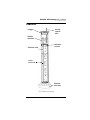
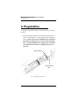
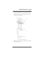
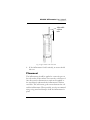
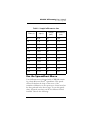
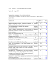
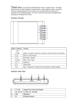
Mini Disk
Infiltrometer
User’s Manual
Version 3
©2006 Decagon Devices, Inc.
All rights reserved.
Decagon Devices, Inc.
950 NE Nelson Court
P.O. Box 835
Pullman WA 99163
Minidisk Infiltrometer User’s Manual
Table of Contents
Contents
1. Introduction . . . . . . . . . . . . . . . . . . . . 1
Welcome . . . . . . . . . . . . . . . . . . . . . . . . . . . . . . .
Specifications . . . . . . . . . . . . . . . . . . . . . . . . . .
Contact Information . . . . . . . . . . . . . . . . . . . . . .
Warranty Information . . . . . . . . . . . . . . . . . . . .
1
1
1
1
2. The Infiltrometer . . . . . . . . . . . . . . .2
How it Works . . . . . . . . . . . . . . . . . . . . . . . . . . . 2
Features . . . . . . . . . . . . . . . . . . . . . . . . . . . . . . . . 3
Hydraulic Conductivity . . . . . . . . . . . . . . . . . . . . 4
3. Preparation
. . . . . . . . . . . . . . . .6
Choosing the Suction Rate . . . . . . . . . . . . . . . . . 8
Placement . . . . . . . . . . . . . . . . . . . . . . . . . . . . . . . 9
4. Collecting Data . . . . . . . . . . . . . . . 10
Use the Spreadsheet Macro . . . . . . . . . . . . . . . 11
Calculate Infiltration . . . . . . . . . . . . . . . . . . . . . 12
References . . . . . . . . . . . . . . . . . . . . . . . . . . . . . 14
Additional Reading . . . . . . . . . . . . . . . . . . . . . . 15
5. Maintenance . . . . . . . . . . . . . . . . . 16
Cleaning . . . . . . . . . . . . . . . . . . . . . . . . . . . . . . . 16
Suction Tube . . . . . . . . . . . . . . . . . . . . . . . . . . . 16
i
Minidisk Infiltrometer User’s Manual
Table of Contents
ii
Minidisk Infiltrometer User’s Manual
1. Introduction
1. Introduction
Welcome
Welcome to the mini disk infiltrometer for measuring soil
hydraulic conductivity. The infiltrometer will enable you to
measure the hydraulic conductivity of any soil accurately
and affordably.
Specifications
Total Length - 32.7 cm
Diameter of tube- 3.1 cm
Sintered stainless steel disc: 4.5cm dia.,3 mm thick
Length of suction regulation tube: 10.2 cm
Suction range: 0.5 to 6cm of suction
Length of water reservoir: 21.2 cm
Length of Mariotte tube: 28cm
Volume of water required to operate: 135ml
Contact Information
To contact Decagon for customer support or questions:
• E-mail us at [email protected]
• Send us a fax at: (509) 332-5158
• Call us at: 1-800-755-2751 (US and Canada only) or
509-332-2756.
Warranty Information
The infiltrometer has a 30-day satisfaction guarantee and a
one-year warranty.
1
Minidisk Infiltrometer User’s Manual
2. The Infiltrometer
2. The Infiltrometer
The mini disk infiltrometer is ideal for field measurements; due to its compact size, the water needed to operate it can easily be carried in a personal water bottle. It is
also practical for lab and classroom use, in demonstrating
basic concepts of soil hydraulic conductivity.
How it Works
The upper and lower chambers of the infiltrometer are
both filled with water. The top chamber (or bubble chamber) controls the suction. The lower chamber contains a
volume of water that infiltrates into the soil at a rate determined by the suction selected in the bubble chamber. The
lower chamber is labeled like a graduated cylinder, with
volume shown in mL. The bottom of the infiltrometer has
a porous sintered stainless steel disk which will not allow
water to leak in open air. The small diameter of the disk
allows for undisturbed measurements on relatively level
soil surfaces.
Once you place the infiltrometer on a soil, water begins to
leave the lower chamber and infiltrate into the soil at a rate
determined by the hydraulic properties of the soil. As the
water level drops, you record the volume at specific time
intervals (like every 30 seconds for a silt loam soil). You
can then plot this data using a spreadsheet (included on
CD-ROM with the infiltrometer) to calculate the hydraulic
conductivity.
2
Minidisk Infiltrometer User’s Manual
2. The Infiltrometer
Features
stopper
suction
control
tube
bubble
chamber
chamber
barrier
Mariotte tube
water
reservoir
Sintered
steel disc
Fig.1: Infiltrometer diagram
3
Minidisk Infiltrometer User’s Manual
2. The Infiltrometer
Hydraulic Conductivity
The mini disk infiltrometer measures the hydraulic conductivity of the medium it is placed upon. In Principles of
Soil and Plant Water Relations by M.B. Kirkham (2005),
hydraulic conductivity is defined as “the meters per day of
water seeping into the soil under the pull of gravity or
under a unit hydraulic gradient.” This is different than
infiltration rate, which is defined as “the meters per unit
time of water entering into the soil regardless of the types
or values of forces or gradients.” Hydraulic conductivity is
useful to scientists, land managers, and growers, in knowing how quickly water will infiltrate when applied to a
given field or soil type. Infiltration is also relevant in fields
of study such as contaminant transport, ground water
recharge and ecosystem sustainability.
Because the infiltrometer has an adjustable suction (0.5 to
6 cm) you can get additional information about the soil by
eliminating macropores with an air entry value smaller
than the suction of the infiltrometer. This is done by controlling the infiltration with a small negative pressure or
suction. When the water is under tension or suction, it will
not enter macropores such as cracks or wormholes, but
will only move into and through the soil as determined by
the hydraulic forces in the soil.
Saturated conductivity is obtained when all the pores,
including the large ones (such as cracks or wormholes),
are filled. Macropore flow, however, is extremely variable
from place to place, and therefore difficult to quantify.
Infiltrating water under a tension prevents the filling of
the macropores and gives a hydraulic conductivity characteristic of the soil matrix, and is less spatially variable.
4
Minidisk Infiltrometer User’s Manual
2. The Infiltrometer
Soil hydraulic conductivity is a function of water potential
and water content of the soil. The decrease in conductivity
as the soil dries is due primarily to the movement of air
into the soil to replace the water. As the air moves in the
pathways for water flow between soil particles becomes
smaller and more tortuous, and flow becomes more
difficult.
5
Minidisk Infiltrometer User’s Manual
3. Preparation
3. Preparation
To prepare the infiltrometer for measurement, do the following:
1. Fill the bubble chamber by running water down the
suction control tube or removing the upper stopper as
shown. Note: Do not use distilled water. Soil water
has solutes and clays have salts on the exchange
sites. Using distilled water changes the ionic balance and may flocculate or disperse the clay in
the soil.
upper stopper
suction control
tube
Fig. 2: Filling the upper chamber
6
Minidisk Infiltrometer User’s Manual
3. Preparation
2. Once the upper chamber is full, slide the suction control tube all the way down, invert the infiltrometer,
remove the bottom elastomer with the porous disk,
and fill the water reservoir.
Fig. 3: Removing the bottom elastomer
3. Replace the bottom elastomer, making sure the porous
disk is firmly in place.
7
Minidisk Infiltrometer User’s Manual
3. Preparation
Choosing the Suction Rate
Since different soil types will infiltrate water at different
rates, measuring the change of volume vs. time can often
be difficult, particularly in a sandy soil where the water will
infiltrate rapidly. Therefore, you can adjust the suction rate
to better accomodate measuring infiltration for the type of
soil you are measuring. For most soils, a suction rate of
2cm should be adequate. In particularly sandy soils
where infiltration will occur very quickly, an adjustment to
6cm may be helpful, and for more compact soil where
infiltration is much slower, a suction rate of 0.5 is recommended. However, we generally recommend that adjusting the suction to rates other than 2cm should be
reserved to more advanced users who are comfortable
with the instrument and theory of operation.
To adjust the suction rate, move the suction tube up or
down so the water level is even with the desired suction
rate marked on the side of the tube. If the suction tube is
difficult to move, apply a small amount of vacuum grease
on the tube to ease movement. Small suctions allow large
pores to fill; large suctions allow only small pores to fill.
8
Minidisk Infiltrometer User’s Manual
3. Preparation
.
Adjustable
suction
tube
Fig. 4: Upper chamber and suction tube
4. If the infiltrometer is held vertically, no water should
leak out.
Placement
The infiltrometer should be applied to a smooth spot on
the soil surface. If the surface is not smooth, a thin layer of
fine silica sand or diatomaceous earth can be applied to
the area directly underneath the infiltrometer’s stainless
steel disk. This will ensure good contact between the soil
and the infiltrometer. When possible, we also recommend
using a ring stand and clamp to hold the infiltrometer in
place.
9
Minidisk Infiltrometer User’s Manual
4. Collecting Data
4. Collecting Data
To make the hydraulic conductivity measurement, make
sure you have first prepared the instrument as described in
the previous chapter. Then do the following:
1. Record the starting water volume.
2. At time zero, place the infiltrometer on the surface,
assuring that it makes solid contact with the soil surface.
3. Record volume at regular time intervals as the water
infiltrates. The time interval you choose is based on
both the suction rate you select and the soil type being
measured. For example, a sand will typically be 2-5
seconds between readings, a silt loam every 30 seconds, and a tight clay 30 to 60 minutes.A typical data
set will look like the first and third columns of Table 1.
Fig. 5: Timed infiltration
10
Minidisk Infiltrometer User’s Manual
4. Collecting Data
Table 1: Sample infiltrometer data
Time (s)
Volume
(mL)
sqrt (t)
Infiltration
(cm)
0
0.00
95
0.00
30
5.48
89
0.39
60
7.75
86
0.58
90
9.49
83
0.77
120
10.95
80
0.97
150
12.25
77
1.16
180
13.42
75
1.29
210
14.49
73
1.42
240
15.49
71
1.55
270
16.43
69
1.68
300
17.32
67
1.81
Use the Spreadsheet Macro
Your infiltrometer was shipped with a CDROM containing a basic Microsoft Excel® spreadsheet. This spreadsheet will calculate the slope of the curve of the
cumulative infiltration vs. the square root of time based on
the data gathered in the above steps. To use this spreadsheet, first make sure that your PC has Microsoft Excel
installed. Then do the following:
11
Minidisk Infiltrometer User’s Manual
4. Collecting Data
1. Open the file. You will see a table similar to the one
above.
2. Input the volume levels you recorded into the corresponding volume column, and correlated with the
time column on the left. You may need to extend the
columns depending on how much data you have
recorded. The square root of time column and infiltration column will change automatically based on your
data, and the graph on the right of the table will
update to reflect the changes.
3. Save the data as a new spreadsheet on your hard drive.
Calculate Infiltration
A number of methods are available for determining soil
hydraulic conductivity from these data. The method proposed by Zhang (1997) is quite simple, and works well for
measurements of infiltration into dry soil. The method
requires measuring cumulative infiltration vs. time and fitting the results with the function
(1)
I = C1t + C2 t
where C1 (m s-1) and C2 (m s-1/2) are parameters. C1 is
related to hydraulic conductivity, and C2 is related to soil
sorptivity. The hydraulic conductivity of the soil (k) is then
computed from
C1
(2)
A
where C1 is the slope of the curve of the cumulative infiltration vs. the square root of time, and A is a value relating
the van Genuchten parameters for a given soil type to the
k=
12
Minidisk Infiltrometer User’s Manual
4. Collecting Data
suction rate and radius of the infiltrometer disk. A is computed from:
A=
11.65(n 0.1 − 1) exp[2.92(n − 1.9)αho ]
(αro ) 0.91
A=
11.65(n − 1) exp[7.5(n − 1.9)αho ]
(αro ) 0.91
n>1.9
(3)
0.1
n<1.9
where n and α are the van Genuchten parameters for the
soil, ro is the disk radius, and ho is the suction at the disk
surface. The mini disk infiltrometer infiltrates water at a
suction of -0.5 to -6 cm and has a radius of 2.2 cm. The
van Genuchten parameters for the 12 texture classes were
obtained from Carsel and Parrish (1988). Values of A
computed for the mini disk infiltrometer are given in
Table 2.
Table 2: van Genuchten parameters for 12 soil texture classes and A values for a 2.2 cm disk radius and
suction values from 0.5 to 6 cm.
Texture
sand
loamy sand
sandy loam
loam
silt
silt loam
sandy clay loam
clay loam
silty clay loam
sandy clay
silty clay
clay
α
0.145
0.124
0.075
0.036
0.016
0.020
0.059
0.019
0.010
0.027
0.005
0.008
n
2.68
2.28
1.89
1.56
1.37
1.41
1.48
1.31
1.23
1.23
1.09
1.09
ho
-0.5 -1.0 -2.0 -3.0 -4.0 -5.0 -6.0
A
2.9 2.5 1.8 1.3 0.9 0.7 0.5
3.0 2.8 2.5 2.2 1.9 1.6 1.4
4.0 4.0 4.0 4.0 4.0 4.1 4.1
5.6 5.8 6.4 7.0 7.7 8.4 9.2
8.1 8.3 8.9 9.5 10.1 10.8 11.5
7.2 7.5 8.1 8.7 9.4 10.1 10.9
3.3 3.6 4.3 5.2 6.3 7.6 9.1
6.0 6.2 6.8 7.4 8.0 8.7 9.5
8.1 8.3 8.7 9.1 9.6 10.1 10.6
3.4 3.6 4.2 4.8 5.5 6.3 7.2
6.2 6.3 6.5 6.7 6.9 7.1 7.3
4.1 4.2 4.4 4.6 4.8 5.1 5.3
13
Minidisk Infiltrometer User’s Manual
4. Collecting Data
4. A quadratic equation is included in the Excel spreadsheet. Columns 2 and 4 from the table are used to produce an XY (scatter) plot to the right of the table.
This is used to calculate C1, which is the slope of this
line, denoted as “y.” An example is shown in the graph
below:
Cumulative Infiltration (cm)
2.00
y = 0.0028x 2 + 0.0575x
R2 = 0.9987
1.50
1.00
0.50
0.00
0
5
10
15
20
Square Root of Time
In this example, the value of C1 is 0.0028 cm s-1. The soil
is a silt loam, so from Table 2, for -2 cm suction, A = 8.1.
The hydraulic conductivity (at 2 cm suction) is therefore
k = 0.0028 cm s-1 /8.1 = 3.45 x 10⁻⁴ cm/s.)
A much more extensive discussion of tension infiltrometer measurement and analysis is given in Dane and Topp
(2002) p. 888-896.
References
Carsel, R. F. and R. S. Parrish. 1988. “Developing joint
probability distributions of soil water retention
characteristics.” Water Resour. Res. 24: 755-769.
14
Minidisk Infiltrometer User’s Manual
4. Collecting Data
Dane, J. H. and G. C. Topp, Eds. (2002) Methods of Soil
Analysis Part 4 - Physical Methods. Soil Science Society of America, Madison, WI.
Kirkham, M.B. (2005) Principles of Soil and Plant Water Relations. Elsevier Academic Press: Burlington, MA.
pp. 145-172.
Zhang, R. 1997. “Determination of soil sorptivity and
hydraulic conductivity from the disk infiltrometer.” Soil Sci. Soc. Am. J. 61: 1024-1030.
Additional Reading
Clothier, B.E. (2001) “Infiltration.” Soil and Environmental
Analysis. Edited by Keith A. Smith and Chris Mullins.
15
Minidisk Infiltrometer User’s Manual
5. Maintenance
5. Maintenance
Cleaning
All of the infiltrometer parts can be cleaned using mild
soap and water. The stainless steel disk can be cleaned
with a brush or even run in a dishwasher. Since it is stainless steel, it will not rust, cleans easily, and won’t snag or
tear on rags when washing.
Suction Tube
If the suction regulation tube is difficult to move, use a
small amount of vacuum grease to allow it to move more
freely.
16
Index
C
collecting data 10
additional reading 15
calculate infiltration 12
references 14
using the spreadsheet macro 11
contact information 1
E
email 1
F
fax number 1
H
how the infiltrometer works 2
hydraulic conductivity 4
I
infiltrometer
how to use 6
Introduction 1
M
maintenance 16
cleaning 16
suction tube 16
17
P
preparation 6
choosing the suction rate 8
placement 9
probe
features 3
S
seller’s liability 2
specifications 1
T
telephone number 1
W
warranty 1
18