1
Safety Precautions
The following notation conventions are used in this manual to indicate Safety Precautions.
CAUTION
A CAUTION statement indicates a potentially hazardous situation that may result
in personnel injury or equipment damage.
Note:
Provides additional information needed to properly use the balance.
CAUTION
To ensure the proper operation of the balance, observe the following precautions.
• Do not use the balance in hazardous areas.
This includes areas where the balance is exposed to dust and flammable gases or
liquids.
Ÿ Use the AC adapter supplied by CAS.
To prevent the risk of electric shock, never disassemble the AC adapter.
The AC adapter is designed for indoor use. Do not use the adapter in exterior
environments or where it may be splashed by water.
Ensure that the power supply voltage meets the indicated range of the AC adapter.
Ÿ Handle the balance carefully.
The balance is a precision instrument. The door to the weighing chamber is glass,
open and close it carefully.
Ÿ Do not connect the peripheral devices other than those recommended by CAS to the
balance.
The balance may not operate properly if peripheral devices other than those specified
in this manual are used. When using the RS-232C interface, follow the instructions
in Section 34. “Windows DIRECT FUNCTION” and Section 37. “Configuration
Diagram of Peripheral Units.”
Ÿ DO NOT disassemble the balance, accessories, or peripheral unit.
INTRODUCTION
The CAS corporation CAW, CAX, and CAY series electronic balances are high
performance, multiple function balances.
The CAW/CAX/CAY series of balances are equipped with various application
weighing functions, and unit conversion functions. These functions allow for a great
variety of applications when used in conjunction with the peripheral units described in
this manual.
The CAW/CAX series of balances incorporates clock functions, a built-in motor-driven
calibration weight that can automatically calibrate sensitivity without the use of
external weights and also has ISO and GLP corresponding outputs included in the
standard specifications.
Read this manual carefully and keep it with the balance for future reference.
CONTENTS
1.
BALANCE COMPONENT S.................................................................................1
2.
INSTALLATION ..................................................................................................5
3.
WARM-UP..........................................................................................................6
4.
PRECAUTIONS..................................................................................................6
5.
MEASUREMENT PROCEDURE.........................................................................7
6.
MENU SELECTION............................................................................................7
6.1
6.2
6.3
6.4
6.5
6.6
7.
OPERATION MENU ...........................................................................................8
FUNC.SEL MENU .........................................................................................10
SE TTING MENU ............................................................................................12
INTFACE MENU ............................................................................................16
UNIT.SEL MENU ...........................................................................................18
IF:USE R M ENU .............................................................................................20
SPAN CALIBRATION (SENSITIVITY ADJUSTMENT).......................................22
7.1
7.2
7.3
7.4
S PAN CALIBRATION USING THE B UILT- IN W EIGHT.............................................22
S PAN CALIBRATION USING AN EXTERNAL W EIGHT ...........................................23
S PAN C HECK USING THE B UILT- IN W EIGHT......................................................24
S PAN C HECK USING AN EXTERNAL W EIGHT ....................................................25
8.
ZERO TRACKING ............................................................................................26
9.
STABILITY DETECTION BAND ........................................................................26
10.
REGISTRATION, RELEASE, AND SELECTION OF MEASURE-MENT UNITS .26
10.1
10.2
10.3
10.4
P ERCENTAGE................................................................................................27
NUMBER OF P IECES .......................................................................................28
SOLID S PECIFIC G RAVITY ...............................................................................29
LIQUID S PECIFIC G RAVITY ..............................................................................30
11.
AUTO PRINT ....................................................................................................31
12.
ANALOG DISPLAY...........................................................................................31
13.
ADD LOAD WEIGHING ....................................................................................32
14.
STANDARD SPAN CALIBRATION (SENSITIVITY ADJUSTMENT)...................33
15.
EXTERNAL WEIGHT VALUE FOR SPAN CALIBRATION.................................34
16.
EXTERNAL WEIGHT VALUE FOR BUILT-IN WEIGHT CALIBRATION
(CAW/CAX SERIES ONLY) ..............................................................................34
17.
CALIBRATION OF THE BUILT-IN WEIGHT (CAW/CAX SERIES ONLY) ...........35
18.
BALANCE ID NUMBER ....................................................................................35
19.
OUTPUT CORRESPONDING TO GLP/GMP ....................................................36
20.
AUTOMATIC SPAN CALIBRATION (PSC)(CAW SERIES ONLY) .....................37
21.
CLOCK-CAL (CAW SERIES ONLY) ..................................................................38
22.
CLOCK-CAL STARTING TIME (CAW SERIES ONLY) ......................................38
23.
SOLVENT SPECIFIC GRAVITY FOR SOLID SPECIFIC GRAVITY
MEASUREMENT ..............................................................................................39
24.
SINKER VOLUME FOR LIQUID SPECIFIC GRAVITY MEASUREMENT ...........40
25.
DATE (CAW/CAX SERIES ONLY) ....................................................................40
26.
TIME (CAW/CAX SERIES ONLY) .....................................................................41
27.
PRINTING THE DATE & TIME (CAW/CAX SERIES ONLY)...............................42
28.
PERFORMANCE CHECK.................................................................................42
29.
MAINTENANCE................................................................................................44
30.
TROUBLESHOOTING ......................................................................................44
30.1
E RROR MESSAGE..........................................................................................46
31.
SPECIFICATIONS ............................................................................................47
32.
PARTS LIST .....................................................................................................51
33.
USING PERIPHERAL UNITS............................................................................51
34.
WINDOWS ® DIRECT FUNCTION.....................................................................52
35.
INPUT AND OUTPUT DATA FORMAT .............................................................55
36.
COMMAND CODE ...........................................................................................56
37.
CONFIGURATION DIAGRAM OF PERIPHERAL UNITS...................................58
1.
BALANCE COMPONENTS
Composition:
The Instruction Manual and Inspection Acceptance Certificate & Installation
Tag are included along with the items depicted below. Verify that all of the
items are included in the shipping carton.
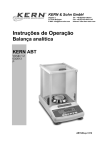
Name of Each Part:
Main Balance Body
4. Anti-draft Ring
7. Glass Doors
10. Keyboard
Connector
13. RS-232C Connector
Symbol Displays
1.
Pan
5. Level
8. Weighing Chamber
11. DATA
I/O
Connector
14. AC Adapter
2.
1
3.
6.
9.
12.
Pan Supporter
Leveling Screw
Case Side Wall
DCIN Connector
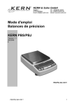
Analog display
Unit display
An example of ìwhole lightingî display.
Display
*
AP
▼
How to read
Meaning during weighing
In mass display this symbol indicates that the balance
Stability
is stable. In menu display, this symbol indicates the
symbol
current menu setting. (*1)
Blinks when sensitivity adjustment is necessary. This
symbol continues to blink until either a manual or
Weight
automatic sensitivity adjustment is made. This symbol
symbol
also blinks when the pre-set time for the Clock-CAL
function is reached.
Num symbol Indicates numeric value entry.
Menu symbol Illuminates during menu selection.
Indicates that the displayed numeric value is not a
Asterisk
mass value.
Add Load
Indicates that Add Load Weighing is ON for the
Weighing
application measurement function.
symbol
Illuminates during communication to external
Communicati
equipment through the RS-232C or DATA I/O
on symbol
connector.
When the balance is operated with the optio nal
Battery
external battery pack, this symbol illuminates to
symbol
indicate that the battery voltage has dropped.
Auto-Print Indicates that Auto-Print is ON for the application
symbol
measurement function.
STAND-BY
Illuminates when the power is in STAND-BY mode.
symbol
Inverse
Illuminates when the solid specific gravity unit is
triangle
used. This symbol is also used as a substitute for the
symbol
decimal point.
*1 Stability symbol
The displayed value may change while the stability symbol remains
illuminated if the load is changing slowly or if the stability detection
band has been set to a large value.
2
Key Functions
Key
During weighing
Pressing Once Pressing and
and Releasing
Holding for
About 3
Seconds
Switches
Exits the
between the
Application
operation and
Measurement
STAND-BY
function.
modes.
During menu selection (*1)
Pressing Once Pressing and
and Releasing
Holding for
About 3
Seconds
Returns to the
Returns to the
previous menu. mass display.
Enters
sensitivity
calibration or
menu selection.
Sets the sample
weight in the air
for solid specific
gravity
measurement.
Tares the
balance.
(Displays zero)
(*5)
Changes the unit
selection. (*2)
Moves to the
next Menu Map
item.
Sends the
displayed value
to an attached
peripheral
device.
*1
*2
Enters the
setting menus
when piece
counting or %
units are
displayed.
Selects and sets
the currently
displayed Menu
Map item.
Switches
Increases the
between the 1d numeric value of
and 10d display. the blinking
(*3)
digit by 1.
During
Moves the
STAND-BY or blinking cursor
mass display,
to the next digit.
the current time
is sent to an
attached
peripheral
device. (*4)
Refer to Section 6. “MENU SELECTION”.
Units other than “g” must be registered and set before they can be used for
measurement. Gramme (or gram) (g) is the only unit that is registered
3
*3
*4
*5
before shipment. To register other units, refer to Section 10.
“REGISTRATION, RELEASE, AND SELECTION OF MEASUREMENT
UNITs”.
When the unit is set to 10d, the resolution of the minimum display is
decreased by one decimal place.
Applicable to CAW/CAX Series balances only.
TARE may be printed on the key instead of →O/T←. However, the
functions of the key are the same.
4
2.
INSTALLATION
•
•
•
Power Supply Voltage
Do not use any AC adapters other than the one provided as a
standard accessory.
Confirm the power supply voltage.
Confirm that the voltage of the power supply conforms to the one
indicated on the AC adapter.
Installation Site
The ideal operating environment for the balance is in a location where
the temperature is 20°C ± 2°C with a relative humidity of 45 - 60%
RH and the conditions are stable.
Install the balance on a solid table. Ideally the table should be made of
stone. Choose a site that is dust free and is not exposed to vibrations,
wind, direct sunlight or electromagnetic fields.
Do not place the balance in an environment where it will be
exposed to corrosive or flammable gasses.
Installation Procedure
(1) Install the pan supporter then the anti-draft ring and finally the pan
in this order.
(2) Level the balance by turning the leveling screws to bring the bubble
of the level indicator into the red circle.
(3) Verify that the pan is empty and connect the AC adaptor to the
outlet.
(4) After self-check, the balance automatically performs span
calibration and OFF is displayed. It is not possible to interrupt the
span calibration that occurs right after the power is turned ON. Span
calibration is not performed with the CAY series balances.
(5) Press the POWER/BRK key. “Whole lighting” is displayed for
about 1 second then the balance automatically goes to a zero mass
display and the balance is ready for weighing.
(6) Press the POWER/BRK key in the mass display to put the balance
in the STAND-BY mode. The STAND-BY symbol illuminates
indicating that the balance is in the STAND-BY mode.
(7) Allow the balance to warm up for 4 hours in the STAND-BY mode.
(8) Conduct the Performance Check. F See Section 28. “Performance
Check.”
(9) Set the date and time on the balance.
F See Section 25 “DATE” and Section 26 “TIME.”
5
Moving the Balance
• Before moving the balance, confirm that it is not in the process of
span calibration. Unplug the AC adapter from the power outlet
and transfer the balance.
Disconnecting the power supply or moving the balance during span
calibration or check may cause balance failure.
3.
WARM-UP
•
•
•
4.
Warming- up the balance for at least four (4) hours allows for
accurate measurement.
Do not disconnect the AC adapter even when the balance is not in
use.
Instead, press the POWER/BRK key to put the balance in the
STAND-BY (warm- up) mode.
Disconnect the AC adapter from the outlet if the balance will not
be used for a period of one month or longer.
PRECAUTIONS
Observe the following precautions.
Note:
•
•
•
•
•
•
•
•
•
Do not insert metal tools inside the balance housing.
Do not open the balance housing.
Do not allow water or other liquids to enter the balance housing.
Do not place a load on the pan that exceeds the mass range of the
balance.
Do not allow magnetized articles near the balance.
Do not connect any instruments to the balance connectors other
than those designated in this manual.
Do not drop anything on the pan.
The doors to the weighing chamber are glass. Open and close
them carefully.
Before transporting the balance, pack the balance into the original
shipping carton to prevent damage.
6
5.
MEASUREMENT PROCEDURE
Preparations Before Measurement
Warm-up the balance before starting measurement.
Setting the Measuring Mode
(1)
(2)
(3)
Press the POWER/BRK key.
The STAND-BY indicator goes out and whole lighting is displayed.
Verify that all segments of the display illuminate.
If the balance is set to automatically perform span calibration it is
executed before zero is displayed.
Zero is displayed and the balance is in the measuring mode.
Measurement
(1) If a weighing vessel (tare) is used, place it on the pan and wait for
the stability symbol ( ) to illuminate, then press the →O/T← key.
6.
(2)
Verify that 0 is displayed.
(3)
Add the sample and read the display after the stability symbol
appears.
MENU SELECTION
This balance is designed to ensure efficient measurement by selecting
measuring parameters to properly fit the environment and purpose of the
weighing. Use Menu Selection to edit the measurement parameters.
The menu of an CAW, CAX, and CAY series balance consists of four levels.
Press the CAL/MENU key to cycle through the items within a menu level.
Press the →O/T← key to choose the current item or move to the next menu
level. Press the POWER/BRK key to move back one level. Press and hold
the POWER/BRK key for more than three seconds to return to the mass
display.
7
6.1
Operation Menu
Frequently used menus are contained in the first menu level
(1)
Press the CAL/MENU key during mass display.
(2)
"i CAL" (or standard span calibration) is displayed. (CAW/CAX
series only)
(3)
The display changes each time the CAL/MENU key is pressed.
When the desired item is displa yed, press the →O/T← key to select
it.
(→): Press the →O/T← key
(←): Press the POWER/BRK key
(↓): Press the CAL/MENU key
0.0000 →
iCAL
→
St.b1t →
Stnd
→
Mass display
Performs selected standard span calibration. (CAW/CAX
series only)
A display of the currently set conditions F See the example of
the default conditions at the bottom of this page.
Sets the Standard Measurement mode
SAmPLE
→
Hi-Stb →
Sets the High Stability mode
Sets the Sample Pouring mode
FUnC.SEL ↔ Enters the next menu leve l (application measurement
and individual setting modes).
F See Section 6.1 “FunC.SEL Menu.”
SettinG
↔
Enters the next menu level (system setting mode).
F See Section 6.2 “SEttinG Menu.”
IntFACE
•
•
•
↔ Enter the next menu level (input/output format setting
mode).
F See Section 6.3 “intFACE Menu.”
Normal measurement is performed with the CAW, CAX, and CAY
series balances by setting the balance to "Stnd" (Standard
Measurement mode). No other settings are required.
If the balance environment is poor and the display does not stabilize
easily, select "Hi-Stb" (High Stability mode).
To perform high speed sampling or sample minute amounts, select
"SAmPLE" (Sample Pouring mode).
(→): Press the →O/T← key
(↓): Press the CAL/MENU key
(←): Press the POWER/BRK key
8
Display of the Currently Set Conditions (Example)
The current balance conditions are displayed in abbreviation.
Indicates that automatic span
Indicates that the GLP
calibration is ON.
corresponding output
is
ON.
S t . b 1
Measuring mode
Standard:
St
Sample Pouring:
displayed.
High Stability:
t
Stability detection band Zero tracking
0.1mg: b1
ON:
t is displayed.
SA
0.5mg:
b5
OFF:t
is
not
Hi
1.0mg:
9
b10
6.2
FUnC.SEL Menu
From the mass display, press the CAL/MENU key repeatedly until
"FUnC.SEL" is displayed. Press the →O/T← key to enter the next menu
level. Items in this menu level include span calibration, zero tracking,
stability detection band, selection or release of units, automatic PRINT,
analog display and Add Load Weighing.
FUnC.SEL
→
Starts span
calibration using the external
weight.
E tESt→ Starts span check using the
CAL
E CAL
trC:on
i CAL → Starts span calibration using the
built- in weight. (CAW/CAX
series only)
i tESt → Starts span check using the
built- in weight. (CAW/CAX
series only)
trC-on → Sets Zero tracking ON.
external weight.
trC-oF → Sets Zero tracking OFF.
bAnd:1
b-1
→ Sets the stability detection band
b-5
→ Sets the stability detection band
to 1 count.
to 5 counts.
Unit.SEL ↔
b-10 → Sets the stability detection band
to 10 counts.
Enters into the next menu level (unit
selection mode)
F See Section 6.4 “Unit.SEL Menu"
AtPrt:on
AP-on → Sets Automatic PRINT ON.
AP-oF→ Sets Automatic PRINT OFF.
AdiSP:on
Ad-on → Sets Analog display ON.
Ad-oF → Sets Analog display OFF.
10
Addon:on
Weighing mode ON.
Adon-on →
Sets Add Load
Adon-oF →
Sets Add Load
Weighing mode OFF.
(→): Press the →O/T← key
(←): Press the POWER/BRK key.
(↓): Press the CAL/MENU key.
• For better stability at zero point, set the zero tracking ("trC-on" and
"trC-oF") to "trC-on." To observe the variation of the mass amount when
a liquid or powder is slowly injected, set zero tracking to "trC-oF."
• The stability detection band is normally set to "b-1."
• When the stability detection band is set larger, a less stable mass display
is required to light the stability mark.
11
6.3. SEttinG Menu
From the mass display, press the CAL/MENUkey repeatedly until
"SEttinG" is displayed. Press the →O/T← key to enter into the next menu
level. Items that are set in this menu level include calibration of the built- in
weight, standard span calibration, external weight value for span calibration,
external weight value for calibration of the built- in weight, balance ID,
solvent and sinker specific gravity, execution time for Clock-CAL, date,
time, printing corresponding to GLP/GMP, automatic span calibration,
Clock-CAL and date/time print.
Operate the keys according to the following descriptions to set each item.
Select standard span calibration method:
SEttinG
CAL dEF
E CAL → Sets the span calibration
with the external weight.
E tEST →
Sets the span check
with the external weight.
i CAL → Sets the span calibration with
the built- in weight. (CAW/CAX
series only)
i tESt → Sets the span check with the builtin weight. (CAW/CAX series
only)
CAL SEt ↔
Enters the next menu level (external weight
value setting mode).
F See Section 15. “EXTERNAL WEIGHT
VALUE FOR SPAN CALIBRATION.”
PCAL.SEt
↔
Enters the next menu level
(setting mode of an external weight value
for the built-in weight calibration). *1
F See Section 16. “EXTERNAL WEIGHT
VALUE FOR BUILT-IN WEIGHT
CALIBRATION.”
PcAL
↔
Enters the next menu level (calibration
mode of the built- in weight). *1
F See Section 17. “CALIBRATION OF
THE BUILT-IN WEIGHT.”
id:1234 ↔
Enters the next menu level (Balance ID
setting mode).
F See Section 18. “BALANCE ID
NUMBER.”
GLP:on
GLP-on →
Sets the GLP/GMP
corresponding output to ON.
GLP-oF →
Sets the GLP/GMP
corresponding output to OFF.
12
ACAL:on
ACAL-on→ Sets
automatic
span
calibration to ON. (CAW series
only)
ACAL-oF→ Sets
automatic
span
calibration to OFF. (CAW series
only)
A
B
(→): Press the →O/T← key
(↓): Press the CAL/MENU key.
13
(←): Press the POWER/BRK key.
A
B
tCAL:on
tCAL-on →
Set Clock-CAL to
ON. (CAW series only)
tCAL oF →
Set Clock-CAL to
OFF. (CAW series only)
tCAL t1 ↔
tCAL t2 ↔
Enters the next menu level (Clock-CAL
automatic span calibration time setting
mode). (CAW series only)
F See Section 22. “Clock- CAL STARTING
TIME.”
Enters the next menu level (Clock-CAL
automatic span calibration time setting
mode). (CAW series only)
F See Section 22. “Clock- CAL
STARTING TIME.”
tCAL t3 ↔
Enters the next menu level (Clock-CAL
automatic span calibration time setting
mode). (CAW series only)
F See Section 22. “Clock- CAL
STARTING TIME.”
LSG SEt ↔
Enters the next menu level (setting of the
solvent specific gravity for solid specific
gravity measurement)
F See Section 23. “SOLVENT SPECIFIC
GRAVITY FOR SOLID SPECIFIC
GRAVITY MEASUREMENT.”
Sv SEt ↔
Enters the next menu level (setting of the
sinker volume for liquid specific gravity
measurement)
F See Section 24. “SINKER VOLUME
FOR LIQUID SPECIFIC GRAVITY
MEASUREMENT.”
d-01.21 ↔
Enters the next menu level (date setting
mode). (CAW/CAX series only)
F See Section 25. “DATE.”
14
t-16:50
Prtdt:on
SEC AdJ
↔
tm.AdJ
↔
Enters the next menu level
(±30 sec adjustment mode).
(CAW/CAX series only)
F See Section 26. “TIME.”
Enters the next menu level
(time setting mode).
(CAW/CAX series only)
F See Section 26. “TIME.”
Prdt-on → Sets Date and time PRINT ON.
(CAW/CAX series only)
Prdt-oF → Sets Date and time PRINT OFF.
(CAW/CAX series only)
(→): Press the →O/T← key
(←): Press the POWER/BRK
key.
(↓): Press the CAL/MENU key.
15
6.4
intFACE Menu
From the mass display, press the CAL/MENU key repeatedly until
"intFACE" is displayed. Press the →O/T← key to enter the next menu level.
Select the input and output format in this menu. Five preset configurations
are available.
Select a standard format to set the registered baud rate, parity (and bit
length), stop bit, delimiter, and data format all at the same time.
A user format is provided in addition to the preset formats. The user can edit
the communication parameters individually in the user format.
IntFACE
iF :F1
→
Sets format 1.
iF :F2
→
Sets format 2.
iF :F3
→
Sets format 3.
iF :F4
→
Sets format 4.
iF :win
→
Windows ® Direct format.
F See Section 34. “Windows® Direct
iF :USEr ↔
Enters the third hierarchical menu (user
F See Section 6.5 “iF:USEr Menu.”
Function.”
format setting).
(→): Press the →O/T← key
(↓): Press the CAL/MENU key.
16
(←): Press the POWER/BRK key.
Communication parameters for intFACE --- F1s to F4
LCD
display
Applicable model
(manufacturer)
Baud
rate
Handshake
Delimiter
Parity
(bit length)
Stop
bit
Format
iF:F1
AEG
1200
Hardware
C/R
None (8)
1
UF1
iF:F2
AEG expansion
format
1200
Hardware
C/R
None (8)
1
UF2
1
UF3
1
UF4
Even
number
(7)
Odd
number
(7)
iF:F3
Mettler
2400
Hardware
C/R+L/F
iF:F4
Sartorius
1200
Hardware
C/R+L/F
iF:win
Windows ®
Direct
300
Software
win
None (8)
1
UF1
iF:US
Er
User setting
←
←
←
←
←
←
* F1 is the standard communication format used by CAS corporation.
* Set the format to “F1” when using an Electric Printer EP-60A.
* F2 is the expansion of F1. When this format is set, the balance will send
the mass result to the PC.
17
6.5
Unit.SEL Menu
The units available for selection by pressing the UNIT key during mass
display are set in this menu.
From the mass display, press the CAL/MENU key repeatedly until
"FUnC.SEL" is displayed. Then press the →O/T← key repeatedly until
"Unit.SEL" is displayed to enter the unit registration and release menu.
Registration or Release of:
Unit.SEL
Ug
→
A
Gram (0.0001g)
U-
mg →
U-
%
U-
PCS →
U-
ct
U-
mom →
U-
,d
→
Solid specific gravity
U-
d
→
Liquid specific gravity
U-
Lb
→
Pound
U-
Oz
→
Ounce
U-
Ozt →
Troy Ounce
U-
HK →
Hong Kong's tael
U-
SporE→
Singapore tael
U-
tiwAn
→
U-
mAL →
Malaysia tael
U-
ChinA
→
U-
dwt →
Pennyweight
Miligram (0.1mg)
→
Percentage
Number of pieces e
→
Carat (0.001ct)
Momme (0.00005mom)
Taiwan tael
During measurement,
these items are
distinguished among
them by the position of
the symbol, that appears
in the right part of the
display. China tael has no
symbol.
Chinese tael
B
(→): Press the →O/T← key
(↓): Press the CAL/MENU key.
18
(←): Press the POWER/BRK key.
A
B
U-
GN
→
Grain
U-
m
→
Mesghal
U-
b
→
Baht
U-
t
→
Tola
U-
o
→
Parts Pounds
(→): Press the →O/T← key
(↓): Press the CAL/MENU key.
(←): Press the POWER/BRK key.
Units in AW/AX/AY series are converted with the following values.
1g
=0.001kg
=1000mg
=5ct
=0.266667 mom
=0.00220462 Lb
=0.0352740 Oz
=0.0321507 Ozt
=0.0267173 TL-HK
=0.0264555 TL-Singapore
=0.0266667 TL-Taiwan
=0.0264600 TL-Malaysia
=0.0266071 TL-China
=0.643015 dwt
=15.4324 GN
=0.216999 m
=0.0657895 b
=0.0857339 t
=1.12877 o
Note: The unit of parts pounds can not be properly printed.
19
6.6
iF:USEr Menu
From the mass display, press the CAL/MENU key repeatedly until
"intFACE" is displayed. Press the →O/T← key when "intFACE" is
displayed, then press the CAL/MENU key repeatedly until "iF:USEr" is
displayed. To enter the user communication format menu, press the
→O/T← key when "iF:USEr" is displayed. Baud rate, parity (and bit
length), stop bit, delimiter, data format, and handshake can be set
individually in the user format.
Operate the keys according to the following descriptions and perform each
setting. (**** is the current setting.)
iF :USEr
io.b:****
io.d:****
b- 300 →
Sets the baud rate to 300 bps
b- 600 →
Sets the baud rate to 600 bps
b-1200 →
Sets the baud rate to 1200 bps
b-2400 →
Sets the baud rate to 2400 bps
b-4800 →
Sets the baud rate to 4800 bps
b-9600 →
Sets the baud rate to 9600 bps
b-19.2k →
Sets the baud rate to 19.2k bps
b-38.4k →
Sets the baud rate to 38.4k bps
d-CR
→
Sets the delimiter to C/R
d-LF
→
Sets the delimiter to L/F
d-CrLF →
Sets the delimiter to C/R+L/F
d-Cn
→
Sets the delimiter to comma
d-win
→
Sets the delimiter to
Windows Direct Format
20
io.P:****
P-no
→ Sets no parity, 8-bit length
P-odd → Sets odd number parity, 7-bit length
P-EvEn → Sets even number parity, 7-bit length
A
B
(→): Press the →O/T← key
(↓): Press the CAL/MENU key.
A
(←): Press the POWER/BRK key.
B
io.S:****
io.F:****
S-S1
→ Sets stop bit to 1 bit
S-S2
→ Sets stop bit to 2 bits
F-UF1 → Sets data format to 1
F-UF2 → Sets data format to 2
F-UF3 → Sets data format to 3
F-UF4 → Sets data format to 4
io.H:****
H-oFF → Sets no handshake
H-SoFt → Sets software handshake
H-HArd → Sets hardware handshake
(→): Press the →O/T← key
(↓): Press the CAL/MENU key.
21
(←): Press the POWER/BRK key.
7.
SPAN CALIBRATION (Sensitivity Adjustment)
The electronic balance measures mass by electronically compensating for
terrestrial gravitation. Since gravitation acceleration varies slightly in
different areas of the world, span calibration is required when the balance is
installed. Temperature also affects accuracy. Calibration should be
performed whenever there is a significant temperature change. It is good
practice to calibrate the balance before making important measurements and
whenever the balance is moved or disturbed, such as if something falls on
the pan.
Though the temperature coefficient of sensitivity of the balance is adjusted
at less than ±2ppm/°C, readability 0.1mg corresponds to 1ppm (0.1mg/100g
= 1×10⁻⁶ ) in regards to 100g weighing. This means that a slight temperature
change may cause a measuring error. The CAW series balances are designed
to automatically perform span calibration when there is a change in room
temperature. This feature is called "Automatic Span Calibration (PSC)"
and is only available on the CAW series balances. The stability of
sensitivity is maintained within ±2ppm regardless of any change in
environmental temperature. It is possible for the operator to perform span
calibration at any time. This is referred to as "Manual Calibration."
Manual Calibration can be performed using an external weight
(CAW/CAX/CAY series) or the built- in weight (CAW/CAX series only).
Span calibration can be automatically performed at designated times up to
three times in a day. This is referred to as "Clock-CAL" and is only
available on the CAW series balances.
7.1
Span Calibration Using the Built -in Weight
Only the CAW/CAX series balances have the built- in weights. The
following procedure describes span calibration using the built- in weights.
Procedure
(1)
Warm-up the balance.
F See Section 3. “WARM-UP.”
(2)
Verify that the balance is level.
(3)
Verify that the balance pan is empty and press the →O/T← key to
zero the display.
From the mass display, press the CAL/MENU key several times.
When "Func.SEL" appears, press the →O/T← key.
(4)
22
(5)
Press the →O/T← key when "CAL
" is displayed.
Press the CAL/MENU key. When "iCAL " appears, press the
→O/T← key.
Span calibration starts at this point.
NOTE: If iCAL has been selected in the CAL dEF menu in SettinG,
then steps (4), (5), and (6) can be
replaced by simply pressing the CAL/MENU key once and then pressing
the O/T key. (iCAL is the standard
setting on CAW/CAX series.) See 14. STANDARD SPAN
CALIBRATION (Sensitivity Adjustment).
(6)
(7)
(8)
When "CAL-2" is displayed, the balance verifies the zero point.
When "CAL 1" is displayed, the built- in weight is automatically
placed on the pan inside the balance.
(9)
When "CAL 0" is displayed, the zero point is verified again.
(10) Span calibration is complete when "CAL End" is displayed for
several seconds and the display returns to mass display.
(11) The calibration result is output to an external unit if the GLP/GMP
corresponding output is ON.
7.2
Span Calibration Using an External Weight
The following procedure describes how to perform the span calibration using
an external weight.
Procedure
(1)
Warm-up the balance.
F See Section 3. “WARM-UP.”
(2)
Verify that the balance is level.
(3)
Verify that the balance pan is empty and press the →O/T← key to
zero the display.
From the mass display, press the CAL/MENU key several times.
When "Func.SEL" is displayed, press the →O/T← key.
(4)
(5) Press the →O/T← key when "CAL " is displayed.
(6) Press the CAL/MENU key. When "E CAL " is displayed, press the
→O/T← key. Span calibration starts at this point.
NOTE: If E CAL has been selected in the CAL dEF menu in SettinG,
then steps (4), (5), and (6) can be replaced by simply pressing the
CAL/MENU key once and then pressing the O/T key. (E CAL is the
23
standard setting on CAY series.) See 14. STANDARD SPAN
CALIBRATION (Sensitivity Adjustment).
(7) Zero appears on the display and blinks.
(8) The predetermined mass for the calibration weight is displayed and
blinks.
(9) Place the correct calibration weight on the pan.
(10) Zero appears on the display and blinks.
(11) Unload the weight.
(12) If the GLP/GMP corresponding output is ON, the calibration result
is output to an external unit.
(13) Span calibration is complete when "CAL End" is displayed for
several seconds and the display returns to mass display.
7.3
Span Check Using the Built-in Weight
The built in weight is only available on the CAW/CAX series balances.
Follow the procedure below to perform span check using the built-in weight.
Procedure
(1)
Warm-up the balance.
F See Section 3. “WARM-UP.”
(2)
Verify that the balance is level.
(3)
Verify that the balance pan is empty and press the →O/T← key to
zero the display.
(4)
From the mass display, press the CAL/MENU key several times.
When "Func.SEL" is displayed, press the →O/T← key.
(5)
Press the →O/T← key when "CAL" is displayed.
(6)
Press the CAL/MENU key. When "itESt" is displayed, press the
→O/T← key.
Span calibration starts at this point.
When "tESt 2" is displayed, the balance verifies the zero point.
(7)
(8)
(9)
When "tEST 1" is displayed, the built- in weight is automatically
placed on the pan inside the balance.
When "tESt 0" is displayed, the balance verifies the zero point again.
(10) The deviation of sensitivity after previous span calibration is
displayed when this check is complete.
(11) If the GLP/GMP corresponding output is ON, the check result is
output to an external unit.
24
(12) Span check is complete when "tEStEnd" is displayed for several
seconds and the display returns to the mass display.
7.4
Span Check Using an External Weight
Follow the procedure below to perform span check using an external weight.
Procedure
(1)
Warm-up the balance.
(2)
F See Section 3. “WARM-UP.”
Verify that the balance is level.
(3)
Verify that the balance pan is empty and press the →O/T← key to
zero the display.
(4)
From the mass display, press the CAL/MENU key several times.
When "Func.SEL" is displayed, press the →O/T← key.
(5)
Press the →O/T← key when "CAL" is displayed.
(6)
Press the CAL/MENU key. When "E tESt" is displayed, press the
→O/T← key. Span check starts at this point.
Zero appears on the display and blinks.
(7)
(8)
(9)
The predetermined mass for the calibration weight is displayed and
blinks.
Place the correct calibration weight on the pan.
(10) Zero appears on the display and blinks.
(11) Unload the weight.
(12) If the GLP/GMP corresponding output is ON, the calibration result
is output to an external unit.
(13) Span check is complete when "tESt End" is displayed for several
seconds and the display returns to the mass display.
25
8.
ZERO TRACKING
(1) From the mass display, press the CAL/MENU key several times.
When "FUnC.SEL" is displayed, press the →O/T← key.
(2) Press the CAL/MENU key several times until "trC:**" is displayed.
The ** indicates the current setting. "on" indicates zero tracking is
activated, and "oF" indicates it is released.
(3) Press the →O/T← key to change the "trC:**" setting.
(4) Each time CAL/MENU is pressed, "trC-oF" or "trC-on" is
displayed. The current setting is displayed with the stability symbol.
When the desired item is displayed, press the →O/T← key to
change the setting, or press the POWER/BRK to return to "trC:**."
(5) When "trC:**" is displayed, press and hold the POWER/BRK key
to return to the mass display.
9. STABILITY DETECTION BAND
(1)
From the mass display, press the CAL/MENU several times. When
"FunC.SEL" is displayed, press the →O/T← key.
(2)
Press the CAL/MENU key several times. When "bAnd:**" is
displayed, press the →O/T← key. The ** indicates the current
setting.
(3)
Each time CAL/MENU is pressed, "b-1", "b-5", and "b-10" are
displayed. The current setting is displayed with the stability symbol.
When the desired item is displayed, press the →O/T← key to
change the setting.
(4)
Press the POWER/BRK key to return to "bAnd:**."
10. REGISTRATION, RELEASE, AND SELECTION OF MEASUREMENT
UNITS
Registration of Measurement Units
(1)
From the mass display, press the CAL/MENU several times. When
"FUnC.SEL" is displayed, press the →O/T← key.
(2)
Press the CAL/MENU key several times. When "Unit.SEL" is
displayed, press the →O/T← key.
Each time the CAL/MENU key is pressed, a unit that can be
registered is displayed.
Currently registered units are displayed with the stability symbol.
(3)
26
(4)
When the desired unit is displayed, press the →O/T← key to
register it.
(5)
To return to the mass display, press and hold the POWER/BRK key.
Release of the Measurement Unit
Perform operations (1) to (3) above to display the units. When the currently
registered unit with the stability symbol is displayed, press the →O/T← key
to release registration of that unit.
Selection of Units
Press the UNIT key during mass display to switch between the registered
units.
If reference values are not set, as with % and PCS, " --- " is displayed
instead of a numeric value.
F See Section 10.1 “Percentage” or Section 10.2 “Number of Pieces” for
more information on setting reference values.
10.1
Percentage
Procedure
This balance is capable of displaying mass values in the % unit by setting a
reference sample as 100%.
(1)
Register the % unit.
F See Section 10. “REGISTRATION, RELEASE, AND
SELECTION OF MEASUREMENT UNITS.” If % unit is already
registered, it is not necessary to register it again.
(2)
Place the weighing vessel on the pan and press the →O/T← key.
(3)
Add the reference sample.
(4)
From the mass display, press the UNIT key to select the % unit.
(5)
Press and hold the CAL/MENU key until "SEt 100%" is displayed.
(6)
Confirm that the stability symbol is lit and press the →O/T← key.
(7)
"SEt" is displayed for several seconds and then the % unit is
displayed.
The minimum display value varies depending on the mass of the reference
sample. (REF.)
The following reference sample mass is the count value when the minimum
display value is regarded as 1.
27
If it is impossible to convert the value into %, "Err 20" appears for several
seconds and then, the display returns to the mass display.
(H type)
<REF.<Min.
display
value×100
Min. display value×100
<REF.<Min.
display value×1000
Min. display value×1000 <REF.<Min.
display
value×10000
Min. display value×10000 <REF.<Min.
display
value×100000
Min. display value×100000
<REF.<Min.
display value×1000000
Min. display value×1000000
<REF.
10.2
% conversion
not possible
100%
100.0%
100.00%
100.000%
100.0000%
Number of Pieces
This balance is able to display the number of pieces (PCS) by measuring the
mass of the sample. The reference numbers to measure unit mass amount
are 10, 20, 50, and 100pcs. The larger the reference number, the higher the
accuracy of measurement. The minimum unit mass is "0.0100 g."
Procedure
(1) Register the number of pieces (PCS) unit.
F See Section 10. “REGISTRATION, RELEASE, AND
SELECTION OF MEASUREMENT UNIT.”
If PCS is already registered, it is not necessary to register it again.
(2)
Place a weighing vessel on the pan and press the →O/T← key.
(3)
Add the number of samples you wish to measure to the pan.
(4)
Confirm that the stability symbol has illuminated.
(5)
Press the UNIT key in mass display to select the PCS unit.
(6)
Press and hold the CAL/MENU key until "SEt 10PCS" is
displayed.
(7)
Every time the CAL/MENU key is pressed, the display changes in
the order "SEt 10PCS", "SEt 20 PCS", "SEt 50 PCS", and "SEt
100 PCS."
(8)
Display the number of pieces you wish to set and press the →O/T←
key.
(9)
"SEt" is displayed for several seconds and the number of pieces is
displayed.
28
10.3
Solid Specific Gravity
Solid specific gravity is calculated by measuring the mass of a solid sample
in the air and in a liquid of known specific gravity. The unit for solid
specific gravity is " , d."
Procedure
(1)
(2)
Install the optional specific gravity measurement kit, SMK-301.
Register the solid specific gravity unit.
F See Section 10. “REGISTRATION, RELEASE, AND
SELECTION OF MEASUREMENT UNITS.”
(3)
Set the specific gravity of the liquid.
F See Section 23. “SOLVENT SPECIFIC GRAVITY FOR SOLID
SPECIFIC GRAVITY MEASUREMENT.”
(4)
Press the UNIT key from the mass display to select "d". While
measuring the mass in the air, the g unit is also illuminated.
(5)
Press the →O/T← key.
(6)
Place the sample on the upper pan.
(7)
When stability symbol illuminates, press the CAL/MENU key.
(8)
Next, place the sample on the pan in the liquid. Ensure that the
entire sample is immersed in the liquid. The display indicates the
specific gravity of sample.
Start the measurement of the next sample from step (5).
(9)
29
10.4
Liquid Specific Gravity
Liquid specific gravity is calculated using values obtained by measuring the
weight of the sinker (solid of known volume) in the air and in the sample
liquid. The display unit for liquid specific gravity is "d."
Procedure
(1)
(2)
(3)
(4)
(5)
Place the optional liquid sample sinker in a tank containing the
sample liquid.
Register the liquid specific gravity unit.
F See Section 10. “REGISTRATION, RELEASE, AND
SELECTION OF MEASUREMENT UNITS.”
Set the sinker volume for the measurement of liquid specific
gravity.
F See Section 24. “SINKER VOLUME FOR LIQUID SPECIFIC
GRAVITY MEASUREMENT.”
Press the UNIT key from the mass display and select "d". While
measuring the mass of the sinker in the air, the g unit is also
illuminated.
(6)
Press the →O/T← key.
(7)
Place the sinker on the upper pan of the optional SMK-301.
(8)
Press the CAL/MENU key when stability symbol illuminates.
(9)
Next, place the sinker on the pan in the liquid. The display indicates
the specific gravity of the sample.
(10) Start the measurement of the next sample from step (5).
30
11. AUTO PRINT
By setting Auto PRINT, after the displayed value is stabilized, it is output
from DATA I/O and RS232C connector. After that, the displayed value is
output whenever it is stabilized even if a different sample is loaded.
After the gram-display of the balance falls within ±5 counts of zero, the
displa yed value is printed the next time a sample that weights more than 10
counts is loaded and the display is stabilized. Unload the first sample and
allow the display to return to zero ±3 counts before loading the next sample.
Regardless of the unit displayed, 1 count is equivalent to 0.1 mg.
Procedure
(1)
Press the CAL/MENU key several times from the mass display.
When "FUnC.SEL" is displayed, press the →O/T← key.
(2)
Press the CAL/MENU key several times to display "AtPrt:**."
The ** indicate the current setting. "on" indicates that the Auto
Print function is active and "oF" indicates that the function is
released.
To change the settings, press the →O/T← key while "AtPrt:**" is
displayed.
Each time the CAL/MENU key is pressed, the display switches
between "AP-oF" and "AP-on". When the current settings are
displayed, the stability symbol illuminates.
(3)
(4)
(5)
Press the →O/T← key to change the setting, or press the
POWER/BRK key to return to "AtPrt:**" without changing the
settings.
(6)
Press and hold the POWER/BRK key to return to mass display.
12. ANALOG DISPLAY
The CAW/CAX/CAY series balance is equipped to display the ratio of the
current weight against the maximum weighing capacity. This function is
activated or released by setting it to display or not to display.
Procedure
(1)
Press the CAL/MENU key several times from the mass display.
When "FUnC.SEL" is displayed, press the →O/T← key.
(2)
Press the CAL/MENU several times to display "AdiSP:**."
The ** indicate the current settings for the analog display. "on"
indicates that the function is activated and "oF" indicates that the
function is released.
31
(3)
To change the setting, press the →O/T← key while "AdiSP:**" is
displayed.
(4)
Each time the CAL/MENU key is pressed, "Ad-oF" or "Ad-on" is
displayed. The stability symbol illuminates when the current setting
is displayed.
(5)
Press the →O/T← key to change the setting, or press the
POWER/BRK key to return to "AdiSP:**" without changing the
settings.
Press and hold the POWER/BRK key to return to the mass display.
(6)
13. ADD LOAD WEIGHING
This function displays (or prints) the individual weights and summarizes the
total weight of a series of additions to the sample pan. The Addon:**
function must be reset for each series of Add Load Weighing.
Auto PRINT function must be set to ON to use this function. The balance
will return to the zero display automatically when the printer is attached. If a
printer is not attached, press the →O/T← key to manually return the display
to zero after each addition. Press the POWER/BRK to send the total weight
to the printer and return to normal weighing mode.
With printer attached:
Sample weight is sent to the printer upon stabilization, followed by
automatically returning to the zero display. As additional material is added
to the sample, the additional weight is sent to the printer upon stabilization
and the balance returns to the zero display. Press the POWER/BRK key to
send the total weight to printer and return to normal weighing mode.
Without printer attached:
Auto PRINT function must be set ON to use this function. Press the
→O/T← key after each addition is displayed. Press the POWER/BRK key
to display total weight and return to normal weighing mode.
Reset the Addon:** function for each series of Add Load Weighing.
Procedure
(1) Press the CAL/MENU key several times from the mass display.
When "FUnC.SEL" is displayed, press the →O/T← key.
(2)
Press the CAL/MENU several times to display "Addon:**."
The ** indicate the current setting for the Add Load Weighing
function. "on" indicates that Add Load Weighing is active and "oF"
indicates that it is released.
32
(3)
To change the setting, press the →O/T← key while "Addon:**" is
displayed.
Press the CAL/MENU key to switch between "Adon-oF" and "Adonon". The stability symbol illuminates to indicate the current setting.
(4)
Press the →O/T← key to change the setting, or press the
POWER/BRK key to return to "Addon:**" without changing the
settings.
When "Addon:**" is displayed, press and hold the POWER/BRK
key to return to the mass display.
Regardless of the unit displayed, 1 count is equivalent to 0.1 mg.
(5)
14. STANDARD SPAN CALIBRATION (Sensitivity Adjustment)
There are four types of calibration available for the CAW/CAX series
balances and two for the CAY series balances. These calibration types are
described in Section 7. “SPAN CALIBRATION.” The operator sets the type
of calibration that will be performed. The set calibration is the standard span
calibration and appears in the Operation Menu.
Setting the Standard Span Calibration:
Procedure
(1) From the mass display, press the CAL/MENU key several times.
When "SEttinG" is displayed, press the →O/T← key.
(2) When "CAL dEF" is displayed, press the →O/T← key.
(3) Press the CAL/MENU key to display the different types of span
calibration. When the desired type of span calibration is displayed,
press the →O/T← key to set it. This calibration type si now the
standard span calibration and is displayed with the stability symbol.
• "E CAL":
Span calibration using an external weight
• "E tESt":
Span check using an external weight
• "i CAL":
Span calibration using the built- in weight
(CAW/CAX series only)
• "i tESt":
Span check using the built- in weight
(CAW/CAX series only)
(4) To return to mass display from "CAL dEF", press and hold the
POWER/BRK key.
Executing the Standard Span Calibration:
Procedure
(1) From the mass display, press the CAL/MENU key to display the
standard span calibration type.
(2)
Press the →O/T← key to execute standard span calibration.
33
15. EXTERNAL WEIGHT VALUE FOR SPAN CALIBRATION
Procedure
(1) From the mass display, press the CAL/MENU key repeatedly until
"SEttinG" is displayed, press the →O/T← key.
(2) Press the CAL/MENU key several times. When "CAL SEt" is
displayed, press the →O/T← key. The [MENU] and # symbols are
displayed to indicate numeric value entry. Depending on the model,
50.0000, 100.0000, 200.0000 or 300.0000 is displayed with the
leftmost digit blinking.
(3) Change the blinking digit by pressing the UNIT key. Each time the
UNIT key is pressed, the value changes from 1→2→ • • •
→8→9→0→1→ • • •. Press the PRINT key to confirm that value
and move the blinking cursor to the next digit.
(4) Press the →O/T← key to confirm the numeric value of the external
weight for span calibration or press the POWER/BRK key to return
to "CAL SEt" without changing the value.
(5) When "CAL SEt" is displayed, press and hold the POWER/BRK
key to return to mass display.
16. EXTERNAL
WEIGHT
VALUE
FOR
BUILT-IN
WEIGHT
CALIBRATION (CAW/CAX series only)
Procedure
(1) From the mass display, press the CAL/MENU key repeatedly until
"SEttinG" appears, press the →O/T← key.
(2)
(3)
Press the CAL/MENU key several times. Whe n "PCAL.SEt" is
displayed, press the →O/T← key. The [MENU] and # symbols are
displayed to indicate numeric value entry. Depending on the model,
50.0000, 100.0000, 200.0000 or 300.0000 is displayed with the
leftmost digit blinking.
Change the blinking digit by pressing the UNIT key. Each time the
UNIT key is pressed, the value changes from 1→2→ • • •
→8→9→0→1→ • • •. Press the PRINT key to confirm that value
and move the blinking cursor to the next digit.
(4)
Press the →O/T← key to confirm the numeric value of the external
weight for span calibration or press the POWER/BRK key to return
to "PCAL.SEt" without changing the value.
(5)
When "PCAL.SEt" is displayed, press and hold the POWER/BRK
key to return to mass display.
34
17. CALIBRATION OF THE BUILT-IN WEIGHT (CAW/CAX series only)
Procedure
(1) Warm-up the balance.
See Section 3. “WARM-UP.”
(2) Verify that the balance is level.
(3) Verify that the balance pan is empty and press the →O/T← key to
zero the display.
(4) From the mass display, press the CAL/MENU key several times.
When "SEttinG" is displayed, press the →O/T← key.
(5) Press the CAL/MENU key several times. When "PcAL" is
displayed, press the →O/T← key. Calibration of the built- in weight
is initiated.
(6) When "PcAL" is displayed, the balance verifies the zero point.
(7) When the blinking calibration mass value appears, place the correct
calibration mass on the pan.
(8) When "0.0000" appears, remove the calibration mass from the pan.
(9) When "PcAL 1" is displayed, the built- in weight is automatically
placed on the pan inside the balance.
(10) When "PcAL 0" is displayed, the balance verifies the zero point again.
(11) Span calibration of the built- in weight is complete when the display
returns to the mass display.
18. BALANCE ID NUMBER
Procedure
(1) From the mass display, press the CAL/MENU key several times.
When "SEttinG" is displayed, press the →O/T← key.
(2)
Press the CAL/MENU key several times. When "id:****" is
displayed, press the →O/T← key. The [MENU] and # symbols are
displayed to indicate numeric value entry. "id:****" is displayed
with the first digit blinking.
(3)
Change the blinking digit by pressing the UNIT key. Each time the
UNIT key is pressed, the value changes from 1→2→ • • •
→8→9→0→1→ • • •. Press the PRINT key to confirm that value
and move the blinking cursor to the next digit.
(4)
Press the →O/T← key to confirm the balance ID number, or press the
POWER/BRK key to return to "id:****" without changing the value.
(5)
When "id:****" is displayed, press and hold the POWER/BRK key
to return to mass display.
35
19. OUTPUT CORRESPONDING TO GLP/GMP
Procedure
(1)
Press the CAL/MENU key several times from the mass display.
When "SEttinG" is displayed, press the →O/T← key.
(2)
Pressing the CAL/MENU several times displays "GLP:**."
The ** indicate the current settings for output corresponding to
GLP/GMP. "on" indicates that the function is active, and "oF"
indicates that the function is released.
(3)
Press the →O/T← key to change the setting.
(4)
Each time CAL/MENU is pressed, "GLP-oF" or "GLP-on" is
displayed. The current setting is displayed with the stability symbol.
When the desired item is displayed, press the →O/T← key to
change the setting, or press the POWER/BRK to return to "GLP:**."
(5)
When "GLP:**" is displayed, press and hold the POWER/BRK
key to return to the mass display.
36
20. AUTOMATIC SPAN CALIBRATION (PSC)(CAW series only)
When Automatic Span Calibration is selected (ACAL-on) and one of the
following conditions occur, automatic span calibration is initiated.
(1)
(2)
Change in the ambient temperature.
Approximately 4 hours have passed since the previous span
calibration.
If condition (1) or (2) occurs during STAND-BY mode, automatic span
calibration is initiated when the balance is switched back to Operation
mode.
Two Minute Warning
During operation, the weight symbol blinks to indicate that one of the above
conditions has occurred and span calibration will start in approximately two
minutes. To skip the span calibration, press the POWER/BRK key while the
weight symbol is blinking.
Procedure
(1)
(2)
(3)
(4)
(5)
Press the CAL/MENU key several times from the mass display.
When "SEttinG" is displayed, press the →O/T← key.
Pressing the CAL/MENU several times displays "ACAL:**." The **
indicate the current setting for automatic span calibration. "on"
indicates that the function is active and "oF" indicates that the
function is released.
Press the →O/T← key to change the setting.
Each time CAL/MENU is pressed, "ACAL-oF" or "ACAL-on" is
displayed. The current setting is displayed with the stability symbol.
When the desired item is displayed, press the →O/T← key to
change the setting, or press the POWER/BRK to return to
"ACAL:**."
When "ACAL:**" is displayed, press and hold the POWER/BRK
key to return to the mass display.
37
21. Clock-CAL (CAW series only)
Automatic span calibration is initiated when tCAL-on is selected and the
time set at tCAL t1 - t3 in the measuring mode is reached.
Two Minute Warning
During operation, the weight symbol blinks to indicate that the above
condition has occured and span calibration will start in approximately two
minutes. To skip the span calibration, press the POWER/BRK key while the
weight symbol is blinking.
Procedure
(1) From the mass display, press the CAL/MENU key several times.
When "SEttinG" is displayed, press the →O/T← key.
(2)
(3)
(4)
(5)
Press the CAL/MENU key several times to display "tCAL:**." The
** indicate the current setting for automatic span calibration. "on"
indicates that the function is active and "oF" indicates that the
function is turned off.
Press the →O/T← key to change the setting.
Each time CAL/MENU is pressed, tCAL-oF" or "tCAL-on" is
displayed. The current setting is displayed with the stability symbol.
When the desired item is displayed, press the →O/T← key to
change the setting, or press the POWER/BRK to return to
"tCAL:**."
When "tCAL:**" is displayed, press and hold the POWER/BRK
key to return to the mass display.
22. Clock-CAL STARTING TIME (CAW series only)
Span calibration is automatically conducted when "tCAL-on" is selected and
one of the set times is reached.
Up to three separate calibration times may be entered. Use the 24-hour
system to designate the hour and minute of the starting time. When all the
digits are displayed as "_", the time setting is cancelled.
Procedure
(1)
From the mass display, press the CAL/MENU several times. When
"SEttinG" is displayed, press the →O/T← key.
(2)
Press the CAL/MENU key several times. When "tCAL t1", "tCAL
t2" or "tCAL t3" is displayed, press the →O/T← key. The weight,
[MENU] and # symbols are displayed to indicate numeric value
38
entry. "HH:MM" (HH: hour, MM: min) is displayed and the
leftmost digit is blinking.
(3)
Change the blinking digit by pressing the UNIT key to increase the
numeric value by one. The hour can be set from 00 to 23 and the
minutes and seconds from 00 to 59. By setting all of the digits to
"_" the time setting is cancelled. Press the PRINT key to confirm
the current digit and move the blinking cursor to the next digit.
Press the POWER/BRK key to complete the changes. If an illogical
time is entered, "Err 20" is displayed.
(3)
When "tCAL t*" is displayed, press and hold the POWER/BRK key
to return to mass display.
23. SOLVENT SPECIFIC GRAVITY FOR SOLID SPECIFIC GRAVITY
MEASUREMENT
Procedure
(1) From the mass display, press the CAL/MENU key several times.
When "SEttinG" is displayed, press the →O/T← key.
(2)
(3)
Press the CAL/MENU key several times. When "LSG SEt" is
displayed, press the →O/T← key. The [MENU] and # symbols are
displayed to indicate numeric value entry. "SG*.****" is displayed
with the digit next to the G blinking.
Change the blinking digit by pressing the UNIT key. Each time the
UNIT key is pressed, the value changes from 1→2→ • • •
→8→9→0→1→ • • •. Press the PRINT key to confirm that value
and move the blinking cursor to the next digit.
(4)
Press the →O/T← key to confirm the numeric value of the solvent
specific gravity for solid specific gravity measurement or press the
POWER/BRK key to return to "LSG SEt" without changing the
value.
(5)
When "LSG SEt" is displayed, press and hold the POWER/BRK
key to return to mass display.
39
24. SINKER VOLUME FOR LIQUID SPECIFIC GRAVITY MEASUREMENT
Procedure
(1)
From the mass display, press the CAL/MENU key several times.
When "SEttinG" is displayed, press the →O/T← key.
(2)
Press the CAL/MENU key several times. When "Sv SEt" is
displayed, press the →O/T← key. The [MENU] and # symbols are
displayed to indicate numeric value entry. "***.****" is displayed with
the leftmost digit blinking.
Change the blinking digit by pressing the UNIT key. Each time the
UNIT key is pressed, the value changes from 1→2→ • • •
→8→9→0→_→1→ • • •. Press the PRINT key to confirm that
value and move the blinking cursor to the next digit.
(3)
(4)
Press the →O/T← key to confirm the numeric value of the sinker
volume for liquid specific gravity measurement or press the
POWER/BRK key to return to "Sv SEt" without changing the value.
(5)
When "Sv SEt" is displayed, press and hold the POWER/BRK key
to return mass display.
25. DATE (CAW/CAX series only)
Procedure
(1)
From the mass display, press the CAL/MENU key several times.
When "SEttinG" is displayed, press the →O/T← key.
(2)
Press the CAL/MENU key several times. "d-MM.DD" is displayed with
MM and DD indicating the month and day of the currently set date.
(3)
To change the date, press the →O/T← key while "d-MM.DD" is
displayed. The [MENU] and # symbols are displayed to indicate
numeric value entry. The currently set date is displayed as
"YY.MM.DD" with YY indicating the year, MM indicating the
month, and DD indicating the day of the month. The leftmost digit
is blinking.
Change the blinking digit by pressing the UNIT key to increase the
numeric value by one. The year can be set from 00 to 99, the month
from 01 to 12 and 01 to 31 for the day of the month. Illogical month
and day entries are prevented automatically.
Press the PRINT key to confirm the current digit and move the
blinking cursor to the next digit or press the →O/T← key to
complete the changes.
When "d-MM.DD" is displayed, press and hold the POWER/BRK
key to return to mass display.
(4)
(5)
(6)
40
26. TIME (CAW/CAX series only)
The time can be changed by ±30 second increments or by entering the time
completely. Choose the appropriate function according to the amount of
time correction required.
Adjustment by ±30 Second Increments
(1)
From the mass display, press the CAL/MENU several times. When
"SEttinG" is displayed, press the →O/T← key.
(2)
Press the CAL/MENU key several times to display "t-HH:MM." HH
indicates the hour and MM the minutes of the current time.
(3)
To change the time, press the →O/T← key when "t-HH:MM" is
displayed.
(4)
Press the →O/T← key when "SEC AdJ" is displayed.
(5)
Press the →O/T← key to set the seconds value to 00. If the seconds
value was 00 to 29 when the →O/T← key was pressed, 00 sec is set,
and if the seconds value was 30 to 59, the minute is rounded up by
one digit and the seconds value is set to 00.
(6)
Press and hold the POWER/BRK key to return to mass display.
Entering the Time
(1) From the mass display, press the CAL/MENU several times. When
"SEttinG" is diplayed, press the →O/T← key.
(2)
Press the CAL/MENU key several times to display "t-HH:MM." HH
indicates the hour and MM the minutes of the current time.
(3)
To change the time, press the →O/T← key when "t-HH:MM" is
displayed.
(4)
Press the CAL/MENU key. When "tm.AdJ" is displayed, press the
→O/T← key. The [MENU] and # symbols are displayed to indicate
numeric value entry. The currently set time is displayed as "HH:
MM: SS”, where HH indicates the hour, MM indicates the minutes,
and SS indicates the seconds, with the leftmost digit blinking.
Change the blinking digit by pressing the UNIT key to increase the
numeric value by one. The hour can be set from 00 to 23 and the
minute and second from 00 to 59. Press the PRINT key to confirm
the current digit and move the blinking cursor to the next digit.
(5)
(6)
Press the →O/T← key to complete the changes.
(7)
Press and hold the POWER/BRK key to return to the
display.
41
mass
27. PRINTING THE DATE & TIME (CAW/CAX series only)
It is possible to set the balance to send the date and time to a peripheral
device such as a printer. This records the date and time of the internal clock
on the span calibration record.
Procedure
(1)
Press the CAL/MENU key several times from the mass display.
When "SEttinG" is displayed, press the →O/T← key.
(2)
Press the CAL/MENU several times to display "Prtdt:**." The **
indicate the current setting for date and time printing. "on" indicates
that the function is active and "oF" indicates that the function is
released.
To change the setting, press the →O/T← key while "Prtdt:**" is
displayed.
Each time the CAL/MENU key is pressed the display switches
between "Prtdt-oF" and "Prtdt-on".
(3)
(4)
(5)
(6)
Press the →O/T← key to change the setting or press the
POWER/BRK key to return to "Prtdt:**" without changing the
setting.
Press and hold the POWER/BRK key while "Prtdt:**" is displayed,
to return to mass display.
28. PERFORMANCE CHECK
Performance checks should be conducted in an environment where the room
temperature is stable at around 25°C. Use these performance checks to
determine whether the balance is operating properly.
Preparation
• Verify that the balance is warmed-up. F See Section 3.
“WARM-UP.”
• Set the following measuring conditions:
Stnd
(Standard mode)
b-1
(Stability detection band 1 count)
trC-oF (Zero tracking OFF)
42
Repeatability
(1) Load and unload a weight
that is close to the
weighing capacity of the
balance 10 times. Load
the weight on the center
of the pan and record the
values described below.
Xi: Displayed value
when the weight is
loaded.
Yi: Displayed value
when the weight is
unloaded.
(2) Determine the standard
deviations, σx and σy
according to the
formula to the right.
(3) Balance operation is
normal if the values of
both σx and σy are less
than 1.5 times the
standard deviation
specified in Section 31.
“SPECIFICATIONS.”
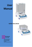
Corner Load Error
(Off center error or Eccentric error)
(1) Prepare a sample that
weighs approximately 1/4
of the balance capacity and
shift it on the pan in the
order shown in the figure to
the right. Record the results
of 1 through 5 in this order.
(2)
If the difference (corner load
error) between readings at
the center position and the
off center positions is less
than 5 counts, the balance
operation is normal.
43
29. MAINTENANCE
Cleaning the balance:
•
•
•
Use a soft cloth containing a neutral detergent to clean the balance.
Avoid using organic solvents, chemicals, or dusting sprays as they
may damage the coatings of the balance or display panel.
The pan can be removed and washed with water. Verify that the pan is
completely dry before replacing it on the balance.
30. TROUBLESHOOTING
Items identified by [S] may require factory service. Please contact your
CAS corporation representative if these problems occur.
When
Trouble
•Cause → Countermeasure
Before
Nothing appears •AC adaptor is disconnected.
measurem on the display.
•The power supply is turned OFF.
ent
•Display
•The balance is exposed to vibration or drafts.
fluctuates.
→ Change the installation site.
•The stability
→ Change the average time and stability
symbol does not
detection band.
light easily.
•Volatile sample.
•Poor
→ Put a lid on the sample before weighing it.
repeatability of •Sample is charged.
measured va lues. → Put the sample in a metallic container and
•Weighed values
then weight it.
deviate from
→ When weighing a plastic disk etc., place a
known values.
sheet of metal larger than the sample on the
•CALd is
pan, and then, weigh the sample.
frequently
•The temperature of the sample is higher or
displayed.
lower than that of the weighing chamber.
During
→ Make the temperature of the sample
measurem
equivalent to that of the weighing chamber.
ent
→ Set the balance to the High Stability mode.
•The balance is exposed to electric noise or
strong electromagnetic wave.
→ Separate the balance and the noise source.
•The balance is exposed to air currents or there
are air convections in the weighing chamber.
→ When the balance is not in use, keep the
door of the weighing chamber open about 1
to 2mm.
•Mechanical damage.
→ [S]
•The balance
•Extreme variation in room temperature or the
frequently enters temperature of unit body.
automatic span
→ Relocate the balance to a location with little
calibration.
temperature variation.
44
•Error such as
ERR0x is
displayed.
•Err20
displayed.
•Hardware failure.
→ [S]
is •The numeric value entered is incorrect.
•The user has attempted to release a registered
unit and the software will not allow it.
→ It is displayed when only one unit is
registered or only the ratio measurement unit
is registered.
•Err24
is •Low battery pack voltage.
displayed.
→ Charge the battery pack.
During
•Display such as •Command code for adjustment is being entered.
measurem t to 10 appeas. → Disconnect the power supply cable. Wait
ent
about 10seconds and reconnect. If this
display is left on the balance for more than
24 hours, it may not be possible to perform
correct measurement.
•The data cannot •Communication parame ter is incorrect.
be transmitted to →
F See Section 35. “INPUT AND
or received from OUTPUT DATA FORMAT.”
the
peripheral
units.
•CAL E2 is
•Something is being placed on the pan during
displayed.
span calibration.
→ Unload it and wait for span calibration to
restart.
During
•CAL E3 is
•The reference weight loaded during calibration
span
displayed.
of the built- in weight is incorrect.
calibration
→ F See Section 17. “CALIBRATION OF THE
BUILT IN WEIGHT.”
•CAL E4 is
•The internal parts of the balance require
displayed.
service.
→ [S]
45
30.1
Error Message
Items identified by [S] may require factory service. Please contact your CAS
corporation representative if these error messages are displayed.
Error
Message
CAL E2
CAL E3
CAL E4
CHE x
Err 0x
Err 20
Err21
Err24
Description
Corrective Action
Zero point deviates largely
during span calibration.
Large
deviation
during
PCAL.
Sensitivity deviates largely
during span calibration.
The balance stops at this
display.
The internal parts of the
balance require service.
An incorrect value has been
entered.
Required conditions and
numeric values are not set.
The balance cannot store
settings due to abnormal
power supply voltage.
Empty the pan.
46
Use
the
correct
calibration mass.
Use
the
correct
calibration mass.
→ [S]
→ [S]
Review
the
entered
numeric value.
Check the analog display
mode.
Check the power supply
voltage.
31. SPECIFICATIONS
Model
Weighing capacity
Minimum display
Standard deviation
σ
Linearity
External weight
value for
calibration
(recommended
value)
Pan diameter
(mm)
Main unit
dimension
Main unit weight
Stability of
sensitivity
(10°C to 30°C)
Operating
temperature range
Power supply
Model
Weighing capacity
Minimum display
Standard deviation
σ
Linearity
External weight
value for
calibration
(recommended
value)
Pan diameter
(mm)
Main unit
dimension
Main unit weight
Stability of
sensitivity
(10°C to 30°C)
Operating
temperature range
Power supply
CAW320
320g
σ ≤0.15mg
CAW220
CAW120
220g
120g
0.1mg
σ ≤0.1mg
±0.3mg
CAX200
200g
±0.2mg
300g
200g
100g
200g
φ80mm
216×315×330
Approx. 7kg
±2ppm: When PSC is ON.
±2ppm/°C: When PSC is OFF.
±2ppm/°C
±5 to 40°C
Input : 100-250VAC, 47-63Hz, 0.3A/Output :
12VDC, 1A
CAX120
120g
CAY220
220g
0.1mg
σ ≤0.1mg
±0.2mg
CAY120
120g
100g
200g
100g
φ80mm
216×315×330
Approx. 7kg
±2ppm/°C
±5 to 40°C
Input : 100-250VAC, 47-63Hz, 0.3A/Output :
12VDC, 1A
47
32. PARTS LIST
Optional Peripherals
Part Name
Part No.
Electronic Printer 321-42008-10
EP-60A
Electronic Printer 321-42008-20
EP-60A
Electronic Printer 321-42008-90
EP-60A
RS232C Cable
321-60754-01
25P-9S (1.5 m)
RS-232C Cable
25P-25P (1.5 m)
Specific gravity
weighing kit
Maintenance Parts
Part name
Pan
Pan supporter
Anti-drift ring
AC adaptor
Level screw
Glass door ASSY,
right
Glass door ASSY,
left
Glass door ASSY,
upper
Front glass
Comments
Including AC
adaptor for 100V
Including AC
adaptor for
100~250V
Without AC
adaptor
For IBM-PC/AT,
DOS/V
(Null modem type)
For some models of
NEC PC-98 series
321-60753-01 (IEEE standard
size)
(Null modem type)
321-60550
Part No.
Remarks
321-60453
321-60459
Including cushion
321-41205
074-83004-01
321-53530-30
321-60445
Including the knob
321-60444
Including the knob
321-60468
Including the knob
321-60430
33. USING PERIPHERAL UNITS
Electronic Printer EP-60A
Procedure
(1) Set the communication format of the balance to “intFACE-iF:F1.”
(2) Disconnect the balance power cable, then connect the electronic
printer to the DATA I/O connector provided on the back of the
balance.
(3)
F For the details, see the Instruction Manual for the Electronic
Printer EP-60A.
48
34. Windows® DIRECT FUNCTION
With CAW, CAX, and CAY series balances, data can be directly transferred
to a PC enabling the displayed values to appear in the application software
of Windows* such as LOTUS 1-2-3 and MS-Excel just as if they were
entered from the keyboard.
Read the final section of this manual before making
these settings in Windows 95.
Procedure
Carefully follow the procedure below.
(1) Turn ON the balance and set the balance communication parameter
to intFACE - iF:win.
(2) Press and hold the POWER/BRK key to escape from menu
selection.
(3)
(4)
Turn OFF the power supplies to the PC and the balance.
Connect the PC and the balance with the RS-232C cable.
(5)
Turn ON the PC only and activate Windows*.
(6)
Select "Start" → "Setting" → "Control Panel" → "Accessibility
Options."
Confirm that there are no check marks next to any items on any of
the tabs including "General."
(7)
(8)
Place a check mark on "Support serial key devices" in the "General"
tab. This will be the only checked item in “Accessibility Options”.
(9)
Open "Setting."
(10) Select a serial port applicable to the RS-232C port of your PC. One
of COM 1 to 4.
(11) Select 300 for "baud rate."
(12) Select "OK."
(13) Select "Update."
(14) Select "Start" → "Shut Down" → "Restart the computer."
(15) After Windows* is fully activated, plug the AC adapter into the
balance power outlet and turn ON the balance.
This completes the setting. It is not necessary to repeat the above settings
each time the balance is used.
49
Checking the Operation
(1)
Open "Note Pad" (or similar application) provided with Windows*.
(2)
Every time the PRINT key is pressed, confirm that the numeric
values displayed on the balance appear on the PC screen.
To end the application, follow the normal end procedure.
(3)
Windows* = Windows ® 95, Windows ® 98, Windows® Me, Windows® 2000
Activate Windows by the following procedure the next time. This ensures correct
operation.
Procedure
(1) Disconnect the balance power supply.
(2) Activate Windows* and wait until activation is complete.
(3) Plug the AC adapter into the outlet and turn ON the balance.
Note:
Turning ON the balance before Windows* is completely activated may
cause incorrect operation.
Note:
• This function may not operate on a PC on which a normal U.S.
version of Microsoft Windows* does not operate. Some types of
personal computers may not be able to use this function or some
features may be limited. CAS does not guarantee that this
function can be used on all the PCs without any problems
currently or in the future.
• CAS is not liable for any direct or indirect problems caused by
this function. It is recommended that important data or programs
on your PC be backed- up before using this function. For the
operation of Windows* or the PC, refer to commercial tutorials or
the appropriate instruction manual.
• It is necessary to have the "Accessibility Options" function of
Windows* installed on the PC. To install "Accessibility Options",
select "Start" → "Setting" → "Control panel" → "Add /Remove
Programs" and open the "Windows Setup" tag. Place a check
mark on "Accessibility Options." For more information, see the
Windows* instruction manual.
• Once the serial key device is made effective, software which uses
the RS-232C port on that PC does not operate correctly, unless it
is made ineffective again. If an external modem, plotter or etc. is
connected, remove the check mark placed on "Using the serial
key device" and re-activate the OS after connection to the balance
is terminated.
50
When the Function Does Not Operate At All:
• For some notebook PCs, it is possible to exclude the RS-232C
port for energy saving purposes. Set the PC so that the RS-232C
port can be used.
• Change the settings of COM 1 to 4. Re-start Windows* after the
changes are complete.
• Verify that the correct RS-232C cable is being used.
Windows* = Windows ® 95, Windows ® 98, Windows® Me, Windows® 2000
When the Function Intermittently Malfunctions:
• Use a communication speed of 300 bps. Depending on the
processing ability of the PC, this function may operate incorrectly
if communication speed is too high.
• Send the next data only after the current one is displayed on the
screen. Depending on the processing ability of the PC, this
function may operate incorrectly if interval of data transmission is
too short.
• Do not touch the keyboard or the mouse while the balance is
transmitting data.
Stop the data transmission and confirm that no data is entering the
PC before touching the keyboard or the mouse.
• This operation may be incorrect when the displayed value is not a
weight value (i.e. error code or time).
• The unit designation is not transmitted.
• This function may operate incorrectly depending on the settings
of various lock keys of the keyboard such as the NUMLOCK or
cursor key lock. Change the state of the lock and function keys on
the PC keyboard.
• The peripheral devices connected to the DATA I/O such as
Electric Printer EP-50 cannot be used with this function.
• When this function is used, a command cannot be sent from the
peripheral device to the balance.
• Set the data formats, such as decimal places and units, in each
application.
51
35. INPUT AND OUTPUT DATA FORMAT
In the following description,
indicates space and [DL] indicates delimiter.
Input Data
[Command Code] + [DL]
F See Section 36. “COMMAND CODE.”
Output Data
• At mass display:
S-200.0000g [DL]*
S-200.0000 [0] g [DL]*
Polarity
•
positive space ( )
negative minus(-)
Stability information
(available to output with stability information)
Stable
S
Unstable
U
When oL or-oL is displayed:
U- oL [DL]
Polarity
positive space ( )
negative minus(-)
Stability information
(available to output with stability information)
Stable
S
Unstable
U
Data Format
• ASCII (JIS) code
• The baud rate, parity (and bit length), delimiter, stop bit, format,
and handshake are changed by menu selection.
52
36. COMMAND CODE
The following commands are available when the balance is connected to a
peripheral device.
☞ For data format, see Section 35.“INPUTANDOUTPUDATAFORMAT.”
If characters or control codes not described here are entered, normal
operation of the balance and correct weighing may be compromised. If
characters or control codes not described here are entered by mistake,
disconnect the power supply cable. Wait about 10 seconds and
reconnect it.
Command Function
code
D01
Continuous output
D05
D06
One time output
Automatic print
D07
One time output with
stability information
D08
One time output at the
stable state
D09
Output stop
Q
ON/OFF selection
T
Taring
TS
CAL or
C18
+
R
g
mg
PERCENT
PCS
CT
Waiting for stability
Taring
Span calibration
Add Load Weighing
Total reset
g unit registration
mg unit registration
% unit registration
"Number of pieces"
registration
"Carat" registration
53
Contents
The balance data is continuously
output at approximately every
230ms.
Equivalent to the PRINT key.
☞ See Section 11. “AUTO
PRINT.”
S or U is output with the data to
indicate the stability state when
the measurement was taken.
S: Indicates the stability symbol
was illuminated.
U: Indicates the stability symbol
was not illuminated.
After the stability symbol is
illuminated and the command is
entered, data is output.
Releases the automatic print and
continuous output functions.
Selection of STAND-BY state
and measuring state.
Equivalent to the →O/T← key
Taring is conducted at the first
stable state after the command is
entered.
Initiates Span Calibration
☞ See Section 13. “ADD LOAD
WEIGHING.”
End/Re lease of various
application weighing
☞ See Section 10.
“REGISTRATION, RELEASE,
AND SELECTION OF
MEASUREMENT UNIT.”
Comman
Function
Contents
d code
MOM "Momme" registration
☞ See Section 10.
“REGISTRATION, RELEASE,
"Solid
specific
gravity"
SDENSE
AND SELECTION OF
registration
MEASUREMENT UNIT.”
"Liquid
specific
gravity"
LDENSE
registration
%
100 % setting
G
g/% selection
-g
"g" registration release
-mg
"mg" registration release
PERCEN "%" registration release
T
"Number of pieces"
-PCS
registration release
"Carat" registration and
-CT
release
-MOM "Momme" registration
release
-SDENSE "Solid specific gravity"
registration release
-LDENSE "Liquid specific gravity"
registration release
High Stability mode
Hi-Stb mode
C02
setting
SAmPLE mode
Stnd mode
Sample
Pouring
mode
C13
setting
☞ See Section 6.1 “Menu Display
C14
Standard setting
when Func.SEL is Selected.”
Stability detection baud
C05
0.1 mg
Stability detection baud
C06
0.5 mg
Stability detection baud
C15
1.0 mg
C07
Performs zero tracking
C08
Not perform zero tracking
Performs automatic span
C10
calibration
Does not perform
C11
automatic span calibration
The measuring conditions
C17
Setting condition check
currently set by menu selection
are output in abbreviation.
54
37. CONFIGURATION DIAGRAM OF PERIPHERAL UNITS
DATA I/O
printer)
EP-60A
(The cable is a standard accessory of the
KEYBOARD
[NEC-PC98 series]
RS-232C
RS-232C cable
(25p-25p 1.5m, Null modem)
[IBM-PC/AT
Compatibles]
RS-232C cable
(25p-9p 1.5m, Null modem)
DC IN
AC adaptor (Standard accessory of the balance)
55