1
Bayfront CAPE Tools
User’s Guide
TM
Bayfront Technologies, Inc.
1280 Bison B9-231
Newport Beach, CA 92660
USA
714.436.0322
Bayfront CAPE Tools™
Users Manual
Version 1.5
Copyright © 1993 by Bayfront Technologies, Inc. All rights reserved. No part of this publication or the
enclosed software may be reproduced or distributed in any form or by any means without the prior written
permission of Bayfront Technologies.
We welcome your suggestions and comments regarding improvements to Bayfront CAPE Tools or this
publication. Changes will be incorporated in new editions of this publication and in new versions of
Bayfront CAPE Tools. Bayfront Technologies reserves the right to make changes to this product at any
time without notice.
The Bayfront CAPE Tools software (including instructions for its use) is provided "as is" without
warranty of any kind. Further, Bayfront Technologies does not warrant, guarantee, or make any
representations regarding the use, or the results of the use, of the software or written materials concerning
the software in terms of correctness, accuracy, reliability, currentness, or otherwise. The entire risk as to
the results and performance of the software is assumed by you. If the software or written materials are
defective, you, and not Bayfront Technologies or its dealers, distributors, agents or employees, assume the
entire cost of all necessary servicing, repair, or correction.
Neither Bayfront Technologies nor anyone else who has been involved in the creation, production, or
delivery of this software shall be liable for any direct, indirect, consequential, or incidental damages
(including damages for loss of business profits, business interruption, loss of business information, and the
like) arising out of the use or inability to use such software even if Bayfront Technologies has been
advised of the possibility of such damages. Because some states do not allow the exclusion or limitations
of liability for consequential or incidental damages, the above limitation may not apply to you.
Bayfront CAPE Tools™, Bayfront CAPEGen™, Bayfront CAPEDraw™, Bayfront CAPESim™ and
sand dollar logo are trademarks of Bayfront Technologies, Inc. Other brand and product names are
trademarks or registered trademarks of their respective holders.
i
Table of Contents
1. Introduction
1.1.
1.2.
1.3.
1.4.
1.5.
1.6.
Computer Aided Protocol Engineering (CAPE).............................................................. 1-1
Communication System Architectures................................................................ ............ 1-2
Client/Server System Architectures ................................................................ ................ 1-3
Realtime System Architectures................................................................ ....................... 1-5
Bayfront CAPE Architectural Model ................................................................ .............. 1-5
Communicating Your Results ................................................................ ........................ 1-7
1.6.1. State Transition Diagram ................................................................ .............. 1-8
1.6.2. State/Event Transition Diagram ................................................................ .... 1-8
1.6.3. SDL Diagram ................................................................ ................................ 1-9
1.7. Organization of the manual................................................................ ............................ 1-10
2. Quick Start
2.1. Installation................................................................ ................................ .....................
2.1.1. Windows Installation................................................................ .....................
2.1.2. DOS Installation................................................................ ............................
2.1.3. Unix Installation................................................................ ............................
2.2. Creating the Protocol Definition Language Input File ....................................................
2.3. Using the Bayfront CAPE Tools for Windows................................................................
2.3.1. File Submenus................................................................ ................................
2.3.2. Edit Submenus ................................................................ ...............................
2.3.3. Compile menu ................................................................ ................................
2.3.4. View Submenus................................................................ ..............................
2.3.5. Options Submenus................................................................ ..........................
2.3.6. Windows Submenus ................................................................ .......................
2.3.7. Help Submenus................................................................ ...............................
2.4. Using the Bayfront CAPEGen Compiler (DOS/Unix).....................................................
2.5. Using the Bayfront CAPEDraw Viewer (DOS)...............................................................
2-1
2-1
2-1
2-1
2-2
2-2
2-2
2-3
2-3
2-4
2-5
2-5
2-5
2-6
2-7
3. Protocol Definition Language (PDL)
3.1. Overview ................................................................ ................................ ....................... 3-1
3.2. PDL Elements................................................................ ................................ ................ 3-1
3.2.1. Spacing, Comments and Syntax Diagrams..................................................... 3-1
3.2.2. Identifiers................................................................ ................................ ...... 3-2
3.2.3. Numbers................................................................ ................................ ........ 3-2
3.3. PDL Structure ................................................................ ................................ ................ 3-3
3.4. States ................................................................ ................................ ............................. 3-3
3.5. Events................................................................ ................................ ............................ 3-4
3.6. Event Macros................................................................ ................................ ................. 3-5
3.7. Actions ................................................................ ................................ .......................... 3-6
3.7.1. Actions on Timers and Messages................................................................ ... 3-6
3.7.2. Action Calls to User Routines................................................................ ........ 3-7
3.7.3. Switch Actions ................................................................ .............................. 3-7
3.8. Action Macros ................................................................ ................................ ............... 3-8
3.9. Error Recovery and Reporting................................................................ ........................ 3-8
3.10. PDL Example................................................................ ................................ ............... 3-9
3.11. PDL Restrictions ................................................................ ................................ .......... 3-9
4. C Code Files
4.1. Overview ................................................................ ................................ ....................... 4-1
4.2. Protocol/State Machine Header File Contents................................................................ . 4-2
iii
4.2.1. State Definitions................................................................ ............................ 4-3
4.2.2. Event Definitions................................................................ ........................... 4-3
4.2.3. Timer Defines ................................................................ ............................... 4-4
4.2.4. Switch Action Return Values................................................................ ......... 4-5
4.2.5. External Action Function Declarations .......................................................... 4-6
4.3. Protocol/State Machine Table File Contents ................................................................ ... 4-6
4.3.1. Include files................................................................ ................................ ... 4-7
4.3.2. Action Parameter Definitions ................................................................ ........ 4-7
4.3.3. Switch Return Value Table and the Switch Table .......................................... 4-7
4.3.4. Action Routines that Pass Parameters ............................................................ 4-8
4.3.5. State/Event To Action Array Jump Table....................................................... 4-9
4.3.6. Action Vector Table ................................................................ ...................... 4-10
4.3.7. State Machine Definition Structure................................................................ 4-10
4.3.8. Interrelations Between Generated Structures.................................................. 4-11
5. State Machine/Protocol Executor
5.1.
5.2.
5.3.
5.4.
5.5.
Calling the State Machine Executor ................................................................ ............... 5-1
State Machine Executor Return Values ................................................................ .......... 5-2
State Machine Test/Debug Procedures................................................................ ............ 5-2
Implementation of a Protocol Layer................................................................ ................ 5-4
Communications Systems Implementation ................................................................ ..... 5-5
6. Action Prototype File
6.1. Action Header File ................................................................ ................................ ......... 6-2
6.2. Action Function Prototype Header File................................................................ ........... 6-2
6.3. Action Function Body File ................................................................ ............................. 6-2
7. Protocol Information File................................................................ ................................ ..... 7-1
8. State/Event Names File ................................................................ ................................ ......... 8-1
Appendix A Error Messages
Bayfront CAPEGen Compiler Error Messages.......................................................... A-1
Bayfront CAPEDraw Viewer Error Messages........................................................... A-3
Appendix B Bayfront Technologies License Agreement ................................................. B-1
Index
iv
List of Figures
Figure 1 : Bayfront CAPE Tools™ Usage................................................................ ............................ 1-1
Figure 2 : International Standards Orgranization ISO Model ............................................................... 1-2
Figure 3 : Inter-Layer Communications ................................................................ ............................... 1-2
Figure 4 : Communicating State Machines within a Layer ................................................................ ... 1-3
Figure 5 : Microsoft's Windows NT Client/Server Model................................................................ ..... 1-3
Figure 6 : Microsoft's Windows DDE Client/Server Model ................................................................ .. 1-4
Figure 7 : DDE Server State/Event Transition Diagram................................................................ ....... 1-4
Figure 8 : Heads Up Display Realtime System ................................................................ ..................... 1-5
Figure 9 : Protocol Layer Architectural Model ................................................................ ..................... 1-6
Figure 10 : Layered Protocol CAPE Architecture Model ................................................................ ...... 1-6
Figure 11 : Client/Server CAPE Architecture Model................................................................ ............ 1-7
Figure 12 : Realtime CAPE Architecture Model ................................................................ .................. 1-7
Figure 13 : Data transfer protocol State Transition Diagram ................................................................ 1-8
Figure 14 : Example State/Event Transition Diagram ................................................................ .......... 1-9
Figure 15 : Example SDL Diagram ................................................................ ................................ ..... 1-10
Figure 16 : Bayfront CAPE Tools User Manual Contents................................................................ ..... 1-11
Figure 17 : Example Protocol Definition Language File................................................................ ....... 2-2
Figure 18 : Bayfront CAPE Tools Main Menus................................................................ .................... 2-2
Figure 19 : CAPEGen Compiler applied to the Q.931 Protocol ............................................................ 2-7
Figure 20 : CAPEDraw Viewer Usage ................................................................ ................................ . 2-8
Figure 21 : Adobe Postscript Output Page Formats ................................................................ .............. 2-9
Figure 22 : Graphic Printers and Formats Supported by the CAPEDraw Viewer.................................. 2-10
Figure 23 : Example PDL Definition ................................................................ ................................ ... 3-1
Figure 24 : Identifier ................................................................ ................................ ........................... 3-2
Figure 25 : PDL Reserved Words................................................................ ................................ ......... 3-2
Figure 26 : Numbers................................................................ ................................ ............................ 3-2
Figure 27 : PDL Structure Syntax ................................................................ ................................ ........ 3-3
Figure 28 : PDL Initial State Syntax ................................................................ ................................ .... 3-3
Figure 29 : PDL State Syntax ................................................................ ................................ .............. 3-3
Figure 30 : PDL Event Syntax ................................................................ ................................ ............. 3-4
Figure 31 : PDL Event Trigger Syntax................................................................ ................................ . 3-4
Figure 32 : PDL Event Macro Syntax ................................................................ ................................ .. 3-5
Figure 33 : PDL Actions Syntax ................................................................ ................................ .......... 3-6
Figure 34 : PDL Action Syntax................................................................ ................................ ............ 3-6
Figure 35 : PDL External Routine Argument Syntax ................................................................ ........... 3-7
Figure 36 : PDL Switch Action Syntax ................................................................ ................................ 3-7
Figure 37 : PDL Action Macro Syntax................................................................ ................................ . 3-8
Figure 38 : PDL Syntax Example ................................................................ ................................ ........ 3-9
Figure 39 : C Code Table File Generation................................................................ ............................ 4-1
Figure 40 : Protocol Layer Architectural Model ................................................................ ................... 4-2
Figure 41 : State Definitions from q931.h ................................................................ ............................ 4-3
Figure 42 : Event Definitions from q931.h................................................................ ........................... 4-4
Figure 43 : Timer Definitions from q931.h ................................................................ .......................... 4-5
Figure 44 : Switch Function Return Values from q931.h................................................................ ...... 4-6
Figure 45 : Portion of External Action Prototypes from q931.h ............................................................ 4-6
Figure 46 : Action Parameter Definitions................................................................ ............................. 4-7
Figure 47 : Switch Table from q931.c................................................................ ................................ .. 4-8
Figure 48 : Switch Return Value Table from q931.c ................................................................ ............ 4-8
Figure 49 : Portion of Action Routines that Pass Parameters from q931.c ............................................ 4-9
Figure 50 : State/Event Table from q931.c................................................................ ........................... 4-9
v
Figure 51 : Portion of the Action Array Jump Table from q931.c......................................................... 4-10
Figure 52 : Portion of the Action Vector Table in q931.c ................................................................ ..... 4-10
Figure 53 : State Machine Definition Structure in q931.c ................................................................ .... 4-11
Figure 54 : Relationships between Generated q931 Structures.............................................................. 4-11
Figure 55 : State Machine Executor Use ................................................................ .............................. 5-1
Figure 56 : CAPE Tools Communications Model ................................................................ ................ 5-1
Figure 57 : Example q931 State Machine Test Program................................................................ ....... 5-3
Figure 58 : Event Processor Pseudo Code ................................................................ ............................ 5-4
Figure 59 : C Files to Implement an Example Four Layer Communications Systems ........................... 5-5
Figure 60 : Action Prototype File Generation................................................................ ....................... 6-1
Figure 61 : actfileh.txt contents ................................................................ ................................ ........... 6-2
Figure 62 : acthdr.txt contents ................................................................ ................................ ............. 6-2
Figure 63 : Q.931 State/Event Names File ................................................................ ........................... 7-2
Figure 64 : State/Event Names File Generation................................................................ .................... 8-1
Figure 65 : State/Event Names File for q931................................................................ ........................ 8-2
vi
Chapter 1 Introduction
1. Introduction
Thank you for purchasing Bayfront Technologies Computer Aided Protocol Engineering (CAPE)
Tools. This chapter introduces the concept of Computer Aided Protocol Engineering (CAPE) and
the structure of the Bayfront CAPE Tools™. If you prefer to immediately install and run the
Bayfront tools, please refer to Chapter 2.
1.1. Computer Aided Protocol Engineering (CAPE)
Realtime systems are different from traditional software systems. A traditional software system
takes input and goes from an initial state to a final state. Typical examples of traditional
software systems are batch, off-line data processing and numerical packages. Realtime systems
such as communications systems, operating systems and process control systems never terminate
in a final state. These systems maintain a continuous interaction with their environment. They
are expected to remain in operation for long periods of time. Protocol systems are a subset of
realtime systems. The Bayfront CAPE Tools were created to address the construction of
communication protocol systems. These same tools can be used to aid the construction of other
realtime systems such as process control systems or client/server systems. Bayfront CAPE Tools:
•
•
•
are used to automate a significant percent of protocol system implementation,
maintenance and documentation
accept user defined protocols or state machines and generate C code implementations
automatically generate state transition diagrams, state/event transition diagrams and
International Telegraph and Telephone Consultative Committee (CCITT) Specification
and Description Language (SDL) diagrams from the input protocol or state machine
description.
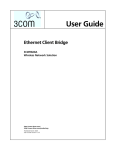
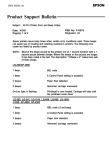
The figure below illustrates the use of Bayfront CAPE Tools.
Protocol
Specification
Protocol
Definition
File
(PDL)
Diagrams:
State Transition File
State/Event Transition File
State Transition
Bayfront
CAPEDraw
Viewer
SDL
SDL File
Protocol Information File
State/Event
Documentation
State/Event Simulation
Bayfront
CAPEGen
Compiler
C Code
State Machine
State +
+ Actions + Primitives
Executor
Tables
Protocol
Implementation
State/Event Names File
Action Prototype File
- User Supplied Information or Routines
Figure 1. Bayfront CAPE Tools™ Usage
Bayfront's CAPE Tools take a user generated protocol definition language (PDL) file as input.
The PDL describes the protocol in terms of protocol-level concepts like states, events and actions.
Bayfront's Cape Tools then create several output files depending on the options selected. These
files include
•
C Code file to implement the protocol
1-1
Bayfront Technologies CAPE Tools™ Users Manual
•
•
•
•
•
•
Action prototype file to assist in the implementation of actions
Protocol Information file for cross reference
State and Event names file for debugging purposes
State Transition Diagram file (pre layout and display format)
State/Event Transition Diagram file (pre layout and display format)
System Description Language (SDL) Diagram file (pre layout and display format).
Implementation is only part of the effort in constructing a successful system. The Bayfront
CAPE Tools also aid the developer in the important documentation, simulation and
validation aspects of system construction. The generation, content, and use of this information
is discussed in detail in the remainder of this manual.
1.2. Communication System Architectures
Communication systems are composed of protocols and state machines contained within
communicating functional layers. A hierarchical set of layers is called a protocol stack. The
International Standards Organization (ISO) Open Systems Interconnection (OSI) model defines
seven such functional layers illustrated in the figure below.
Application Layer
Application Layer
Presentation Layer
Presentation Layer
Session Layer
Session Layer
Transport Layer
Transport Layer
Network Layer
Network Layer
Data Link Layer
Data Link Layer
Physical Layer
Physical Layer
Figure 2 International Standards Organization ISO Model
Each layer consists of communicating protocols or state machines. Interlayer communication
occurs through communications channels, queues or mailboxes depending on the operating
system and implementation details.
The figure below illustrates a general interlayer
communication model.
Layer i+1
Communication Channels/
queues/mailboxes
Layer
Communication Channels/
queues/mailboxes
Layer i-1
Figure 3. Inter-Layer Communications
1-2
Chapter 1 Introduction
Each functional layer contains one or more communicating state machines. These state
machines are driven by a layer event processor and typically react to an incoming event such as a
received message or a timeout. The figure below illustrates a general layer composed of four
state machines and an event processor.
Operating System Events
State
Machine 1
State
Machine 2
Event
Processor
State
Machine 3
State
Machine 4
Operating System Events
Figure 4. Communicating State Machines within a Layer
The layer event processor determines the set of state machines needed to respond to an event. It
then applies the event to those state machines.
1.3. Client/Server System Architectures
Client/Server systems are composed of two different types of processes: clients who request
services and servers who are service providers. This system has the advantage of modularizing
function and well defined interfaces. Newer operating systems such as Microsoft's Windows NT
as well as certain features of Microsoft's Windows OS are based on this model. The figure below
illustrates the Windows NT Client/Server Structure.
Client
Application
Network
Server
File
Server
Win32
Server
Win32
Client
User Mode
Window's NT
Kernel Mode
Figure 5. Microsoft's Windows NT Client/Server Model
Present in the Windows NT environment are servers that provide a specific functionality with a
well defined interface protocol. For example the network server acts on connection, data transfer
and disconnection requests from client applications. The network server must detect clients who
violate the server protocol (e.g. a client who transfers data or disconnects before connecting).
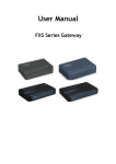
The figure below illustrates Microsoft's Windows Dynamic Data Exchange (DDE) protocol
messages.
1-3
Bayfront Technologies CAPE Tools™ Users Manual
WIndows
WM_DDE_INITIATE
WM_DDE_ADVISE
WM_DDE_REQUEST
WM_DDE_ACK
WM_DDE_UNADVISE
WM_DDE_TERMINATE
Windows
Client
Server
WM_DDE_ACK
WM_DDE_DATA
WM_DDE_TERMINATE
Figure 6. Microsoft's Windows DDE Client/Server Model
The Windows Client and the Windows Server exchange numerous messages. Not all messages
are valid at any one time. Both the Client and Server implement a protocol or state machine that
defines the rules for message transfer. The protocol allows the Server to detect faulty Client
communications and assists the Client in the orderly connection and data transfer with the
Server. The Bayfront generated state/event transition diagram for the DDE Client/Server
protocol is illustrated in the diagram below.
IDLE
rclient_WM_DDE_
INITIATE
INITIATED
rclient_WM_DDE_
REQUEST
rclient_WM_DDE_ADVISE
WAIT_ACK1
DATA_XFER
rclient_WM_DDE_
UNADVISE
rclient_WM_DDE_
REQUEST
rclient_WM_DDE_DATA
PEND_TERMINATE
WAIT_ACK2
WAIT_ACK_REPLY
rclient_WM_DDE_
TERMINATE
rclient_WM_DDE_ACK
rclient_WM_DDE_ACK
Figure 7. DDE Server State/Event Transition Diagram
1-4
rclient_WM_DDE_ACK
Chapter 1 Introduction
Microsoft has itself realized the complexity of the client/server DDE protocol and implemented
an application interface layer on top to try to simplify and make consistent the interface.
Microsoft calls this the Dynamic Data Exchange Management Library (DDEML).
Bayfront's CAPE Tools assist in the design of client/server systems by abstracting and
formalizing the client/server protocols into specific states, events and actions.
1.4. Realtime System Architectures
Realtime system architectures are composed of separate processes which are mutually dependent.
The action of one process may start or stop the activity of other processes. These interdependent
activities between processes must be synchronized. Processes synchronize by exchanging
information through channels, mailboxes or queues. This information exchange is usually
performed according to a protocol or state machine.
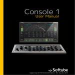
The figure below illustrates a high level architecture of an Aircraft Heads Up Display (HUD)
realtime system.
Navigation
Armament
Process
Process
Heads Up
Display
Process
Target Radar
Process
Figure 8. Heads Up Display Realtime System
The architecture of the Heads Up Display system consists of the interaction of mutually
dependent processes (e.g. armament, navigation, target radar and heads up display processes).
These processes communicate through protocols which define specific states, events and actions.
Bayfront's CAPE Tools provide the realtime developer with a formalism to design the inter- and
intra- process communications.
1.5. Bayfront CAPE Architectural Model
Bayfront CAPE Tools support an architectural model that views an individual communications
layer, realtime process or client/server protocol as composed of an event processor, a state
machine executor, specific protocol state tables and their supporting actions and primitives.
1-5
Bayfront Technologies CAPE Tools™ Users Manual
Events to
Operating System
Events from
Operating System
State Tables
Event
State Machine
Processor
Executor
Action
Primitive
Action
Primitive
Action
Primitive
Action
Primitive
Action
Primitive
Figure 9. Protocol Layer Architectural Model
Because protocol systems are intimately involved with hardware and operating environments the
event processor, actions, and primitives are all programmed by the user of Bayfront CAPE
Tools. Bayfront supplies the state machine executor (sm_exec.c) in source form and example
event processors. The Bayfront CAPEGen Compiler produces the state tables and action function
prototypes from a Protocol Definition Language (PDL) file. Since a layer can consist of multiple
interacting state machines there are state tables and action prototypes for each state machine.
Each state machine is described in a separate PDL file. The benefit of the Bayfront CAPE
Tools is in the analysis, documentation and maintenance of the protocol in protocol-oriented
PDL terms. The error prone alternative is to maintain the state table structures by hand,
hand simulate the states, and hand draw the documentation.
Communications layers are combined using the operating environment communication
mechanisms of streams, queues, communication channels, or mailboxes. This is shown in the
figure below.
Events from
Events to
Operating System
Operating System
Communications Layer i+1
Communications Layer i
Event
State Machine
Processor
Executor
State Tables
Action
Primitive
Action
Primitive
Action
Primitive
Action
Primitive
Action
Primitive
Figure 10. Layered Protocol CAPE Architecture Model
Client/Server systems are composed of a flat architecture of communicating event processors.
This is shown in the figure below.
1-6
Chapter 1 Introduction
Server
Client
Event
Processor
Actions
Communication via:
State
Machine
Executor
- named pipes
- TCP/IP
- NetBios
Event
Processor
State
Machine
Executor
Actions
Primitives
Primitives
Figure 11. Client/Server CAPE Architecture Model
Realtime systems are also composed of a flat architecture of communicating event processors
with a hardware abstraction key to the architecture. This is shown in the figure below.
Realtime
Process 1
State
Machine
Executor
Realtime
Process n
Event
Processor
Event
Processor
State
Machine
Executor
Actions
Actions
Primitives
Primitives
Software/firmware
Hardware
Hardware
Feedback
Control
Hardware
Interrupts
Hardware
Feedback
Control
Figure 12. Realtime CAPE Architecture Model
The user supplied event processor interfaces to the operating system specific routines to receive
events. These events are either completely handled by the event processor or they are translated
into events that are handled by some of the state machines in the layer. These events are defined
in the specific protocol state tables produced by the CAPEGen Compiler. The event processor
invokes the state machine executor with the current state and event. The state machine executor
triggers the execution of actions for the event in the state. The actions depend on supporting user
supplied primitive routines that interface to the operating system and the hardware. When all the
actions are triggered for the specific state/event pair the state machine executor optionally
changes the current state and returns control to the event processor.
The event processor creates a structure called the Event Control Block (ECB) upon the receipt of
each event that contains the context and other useful information. The ECB contains all
information necessary to act on the current event. This information includes a pointer to the
event, a pointer to the specific context of the event, the state machine name and other
miscellaneous fields used for implementation optimization. A more concrete example of the
event processor and state machine interaction is given in Chapter 5.
1.6. Communicating Your Results
The Bayfront CAPEDraw Viewer produces high and low level diagrams of your protocols so that
they may be communicated to others. These graphic representations of your work are useful both
1-7
Bayfront Technologies CAPE Tools™ Users Manual
to the development team and as end-user documentation. The diagrams can be automatically
produced from the same PDL definition used to generate the implementation so there is never a
reason for a diagram to be out of date with the implementation. Three kinds of diagrams are
available; state transition diagrams, state/event transition diagrams, and CCITT Specification
and Description Language (SDL) diagrams.
1.6.1. State Transition Diagram
The state transition diagram shows the possible transitions between the states of the protocol. It is
the highest level diagram of the protocol state machine. The state transition diagram displays the
initial state at the top of the page with all the state interconnections below.
Idle
SetupReceive
SetupSend
Receiving
Sending
WaitAck
Figure 13. Data transfer protocol State Transition Diagram
The figure above shows the state transition diagram for the data transfer protocol (this protocol
can be found in the examples directory). Some of the transitions have arrowheads on only one
end indicating one way transitions. Transitions with arrowheads on both ends imply the protocol
can bounce back and forth between the two states. Some states like Receiving and WaitAck
have transitions to themselves. This indicates that some events are handled in that state without
making a transition to another state.
1.6.2. State/Event Transition Diagram
The state/event transition diagram augments the same transitions shown in the state transition
diagram with the events that cause the transitions. This shows how external events may move
the protocol state machine through its states. The state/event transition diagram displays the
initial state at the top of the page with all states and events below.
1-8
Chapter 1 Introduction
State1
Event2
Event1
State2
Event2
Event1
Figure 14. Example State/Event Transition Diagram
The state transition diagram above tells us that Event1 from State1 causes a transition to
State2.
Note: The state displayed at the top of the diagram is the first state listed in the PDL (after
the InitialState statement). This allows the user to customize the look of the diagram
depending on the state/event connectivity. For example if the initial state is highly
connected compared to other states the diagram will be less complex if the first state is not
displayed at the top.
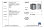
1.6.3. SDL Diagram
The SDL diagrams are the lowest level diagrams of the protocol state machine. There is one
SDL diagram for each state in the protocol. The SDL diagram shows the events and actions that
lead to the transition from one state to another or the same state. The SDL diagram shows the
state name enclosed in a circle at the top of the page. The next row are events followed by
actions and then new state transitions at the bottom.
1-9
Bayfront Technologies CAPE Tools™ Users Manual
WaitAck
rUsr_Disc
rNet_Disc
sNet_Disc
sUsr_Disc
StopAllTimers
StopAllTimers
rNet_NotAck
Tack_timeout
rNet_Ack
Retry
StopTimer(Tack)
YesRetry
NoRetry
StartTimer
(Tsend)
ResendMessage
sUsr_Abort
Sending
RestartTimer
(Tack)
sNet_Abort
WaitAck
StopAllTimers
Idle
Figure 15. Example SDL Diagram
In the SDL diagram for the data transfer protocol state WaitAck shown above we can see that
the event rNet_NotAck is handled in one of two ways. With a retry there is no state transition.
Without retry there is a transition to the Idle state.
1.7. Organization of the manual
A summary of the chapters is described below.
Chapter 1
1-10
Introduces the features, architecture, and environment of the Bayfront CAPE
Tools.
Chapter 1 Introduction
Chapter 2
Provides a quick start for users wishing to install and use the tools with
minimum background reading. This includes installation, the creation of a
Protocol Definition Language (PDL) file, CAPEGen Compiler invocation,
CAPEDraw Viewer invocation, and the resulting output files.
Chapter 3
Describes the syntax and semantics of the Protocol Definition Language
(PDL).
Chapter 4
Describes the C Code output files produced by the CAPEGen Compiler that
are used to implement a protocol.
Chapter 5
Discusses the function, structure and use of the state machine executor.
Chapter 6
Provides a description of the action function prototype files produced by the
CAPEGen Compiler.
Chapter 7
Discusses the structure of the protocol/state machine information file
produced by the CAPEGen Compler for cross reference and documentation
purposes.
Chapter 8
Discusses the use of the states/events names file produced by the CAPEGen
Compiler for state/event simulation and debugging purposes.
Appendix A
Documents the error messages generated by the CAPEGen Compiler and the
CAPEDraw Viewer.
Appendix B
Reproduces the Bayfront License Agreement from the diskette package.
The figure below illustrates the chapter contents in relation to the CAPE Tool output files.
Protocol
Specification
Chapter 1
Protocol
Definition
File
Chapter 3
Diagrams: Chapter 1 & 2
State Transition
State/Event
SDL
Protocol Information File Chapter 7
Chapter 4
Bayfront
CAPE
Tools(tm)
Chapter 2
Chapter 5
C Code
State Machine
State +
+ Actions + Primitives
Executor
Tables
Protocol
Implementation
Chapter 8
State/Event Names File
Chapter 6
Action Prototype File
- User Supplied Information or Routines
Figure 16. Bayfront CAPE Tools User Manual Contents
1-11
Bayfront Technologies CAPE Tools™ Users Manual
1-12
Chapter 2 Quick Start
2. Quick Start
This chapter instructs you how to install and run the Bayfront CAPE Tools™.
2.1. Installation
Bayfront Technologies will ship either a 5 1/4" or 3 1/2" disk with the DOS, Windows or
386/486 Unix versions of the CAPE Tools and a 3 1/2" disk with the SUN Unix version of the
CAPE Tools. If you have the wrong disk type please inform either your local distributor or
Bayfront Technologies for immediate replacement.
2.1.1. Windows Installation
To install the Windows product, insert the disk into the appropriate drive and either from the File
Manager select (double click) the file INSTALL.EXE or from the Program manager choose the
File|Run menus and enter b:install (if the CAPE Tool disk is in the b drive). You will be
prompted to select a directory to install the CAPE Tools or use the default directory
c:\bayfront.
The README file should be read for any last minute information.
2.1.2. DOS Installation
To install the DOS product, insert the disk into the appropriate drive, create a directory
bayfront, and copy the files to the newly created bayfront directory (e.g., xcopy a:
c:\bayfront\ /e/s to copy the files from the a: drive to the c: drive). The final
directory tree will look as follows:
BAYFRONT.DIR
README
CAPEGEN.EXE
CAPEDRAW.EXE
CAPE.H
SM_EXEC.C
ACTHDR.TXT
ACTBODY.TXT
ACTFILEH.TXT
EXAMPLES.DIR
The README file should be read for any last minute information.
2.1.3. Unix Installation
To install the software on a Unix system, insert the disk in the appropriate drive, create a
directory bayfront, and copy the files to the bayfront directory (e.g., tar xvf device
/bayfront/*, where device is the local device name for your floppy drive). After
installation the directory tree will look as follows:
bayfront
readme
cape.h
sm_exec.c
capegen
acthdr.txt
actbody.txt
2-1
Bayfront Technologies CAPE Tools™ Users Manual
actfileh.txt
examples
The readme file should be read for any last minute information. The Bayfront CAPEDraw
Viewer is not available for Unix platforms. Unix CAPE Tool users wishing to generate state,
state/event and SDL diagrams should use the CAPE Tools for DOS (included in the Unix CAPE
Tool package) to layout and display the diagrams on a PC based platform. The DOS CAPE
Tools can generate Postscript files of the diagrams which can be transported and viewed on Unix
platforms with postscript viewers.
2.2. Creating the Protocol Definition Language Input File
The first step in using Bayfront CAPE Tools is to create a Protocol Definition Language (PDL)
input file. PDL files describe a protocol/state machine in terms of states, events and actions. The
protocols can be proprietary or created from standards based recommendations such as from the
CCITT, ANSI, IEEE, and OSI organizations. An example PDL definition is shown below. The
PDL language is described in detail in Chapter 3.
ex1 { InitialState = State1;
state State1::
Event1 -> Action1, Action2 >> State2;
Event2 -> Action3;
state State2::
Event1 -> Action4;
Event2 -> Action5, Action6 >> State1;
}
Figure 17. Example Protocol Definition Language File
The PDL file can be created using any text editor, the Windows CAPE Tools include an
integrated editor. In the example above the PDL describes a protocol/state machine called ex1
with two states, two events and six actions. The initial state is State1. The symbol >>
indicates a transition to a new state. An example transition would be the occurrence of Event1
while in State1, Action1 and Action2 would be executed and the new state would be
State2. See the Bayfront CAPE Tools examples directory for more PDL file examples.
2.3. Using the Bayfront CAPE Tools for Windows
The Windows version of the CAPE Tools provides an easy to use interface. The top menus are
shown below.
File
Edit
Compile
View
Options
Window
Help
Figure 18. Bayfront CAPE Tools Main Menus
All menu options will be deselected or 'grayed out' until they are active. For example if there is
no PDL file selected then the Edit submenus will not apply and all options will be deselected.
In addition to the menu structure above the CAPE Tools support a status line on the bottom line.
The status line provides the user with menu specific information depending on the current
location of the mouse.
2.3.1. File Submenus
The File submenus deal with PDL file opening and closing as well as both file and diagram
saving and printing. The File submenu functions include:
File | New
File | Open
File | Save
2-2
Creates and opens a new PDL file for editing.
Opens an existing PDL file for editing.
Saves the current active PDL window in a file.
Chapter 2 Quick Start
File | Save as
File | Export
File | Print
File | Printer setup
File | Exit
Saves the current active PDL window in a user selectable
file.
Exports a diagram file as an Adobe Postscript® (eps) file.
The user will have the option and be prompted to rotate the
diagram 90 degrees before file creation.
Prints the current active window (PDL, text or diagram).
If text is selected in an edit window then only the selected
text may be printed. Text will be printed in the font
selected in the Options|Edit menu. Diagrams will be
printed using the font selected in the Options|View
menu.
Configures the printer. Note: the printer settings have local
significance only (i.e. within the CAPE Tools only).
Exits the CAPE Tools. If there are any unsaved modified
PDL files open you will be prompted to save them upon
exiting.
2.3.2. Edit Submenus
The Edit submenus deal with the editing of the PDL file. The edit capabilities work in a
similar manner to the Windows predefined edit features. The Edit submenus functions include:
Edit | Cut
Edit | Copy
Edit | Paste
Edit | Delete
Edit | Find
Edit | Replace
Edit | Search
Again F3
Removes the select text into the clipboard.
Copies the selected text into the clipboard (nondestructive
cut). For a view (diagram) window this copies the diagram
to the clipboard as a windows metafile for pasting into
other applications (e.g. MS Word).
Copies the previously selected text from the clipboard to
the current cursor position.
Clears the selected text.
Finds the next occurrence of the user specified text. Find
will pick up the search string from the selected text (can be
manually overridden) if less than a line long.
Replaces the next occurrence of the user specified text with
user specified text. Replace will pick up the search string
from the selected text (can be manually overridden) if less
than a line long.
Repeats the previous Find or Replace operation from the
current cursor.
While in an edit window the right mouse button brings up a popup menu for Help|Topic
Search and the Cut/Copy/Paste/Delete editing functions.
2.3.3. Compile menu
The Compile menu reads the currently loaded and active PDL file and parses it. The output
files specified in the Options|Compile dialog box will be generated upon successful parsing
of the PDL file. Syntax errors detected during the parse will cause the compiler to halt and put
the cursor at the point of error in the PDL window. The status line will indicate an error was
found. Semantic errors such as state unreachable will cause the parser to halt at the end of the
PDL file and open a dialog box with an error message.
When compiling the PDL file the current parse status which includes lines parsed and states
currently parsed will be displayed in the status line at the bottom of the screen.
2-3
Bayfront Technologies CAPE Tools™ Users Manual
2.3.4. View Submenus
The View submenus display the previously generated diagrams for the PDL in the active
window. The selections for the diagram types will be deselected (i.e., grayed) if there are not any
previously generated diagrams by the compiler (see Options | Compile dialog box options).
The View menu also allows the user to zoom in or out to optimize the viewing of selected
diagrams. The View submenus include:
C Header file (.h)
C Code file (.c)
Action prototype file (.act)
Information file (.txt)
Names file (.str)
State transition diagram
State event diagram
SDL diagram
Zoom x25%
Zoom x50%
Zoom x75%
No Zoom
Zoom x125%
Zoom x150%
Zoom x175%
View the C Code header file in a text edit window
View the C Code table file in a text edit window
View the action prototype file in a text edit window
View the protocol information file in a text edit window
View the state/event names file in a text edit window
View the state transition diagram in a diagram window. This
window can be selected and printed by using the File|Print
selection.
View the state/event transition diagram in a diagram window.
This window can be selected and printed by using the
File|Print selection.
Opens a dialog box with a list of the SDL diagrams. The user
can select which diagram to view in a diagram window. This
window can be selected and printed by using the File|Print
selection.
Zooms out of the currently active diagram window by 25%.
Zooms out of the currently active diagram window by 50%.
Zooms out of the currently active diagram window by 75%.
Views the currently active diagram window with no zoom.
Zooms into the currently active diagram window by 125%.
Zooms into the currently active diagram window by 150%.
Zooms into the currently active diagram window by 175%.
All diagrams are automatically laid out before viewing for the first time. The status line will
show the layout progress. On slower CPU's (e.g., 386's) layout might take a few minutes for a
complex diagram.
If the diagram file was generated after the PDL file was modified the CAPE Tools will open a
dialog box cautioning that the diagram might be out of date. The user can then either ignore the
warning and display the diagram or generate an updated diagram file. SDL diagrams can be
displayed all at once (i.e., all states) or the user can specify which diagram to display.
All diagrams can be minimized for later viewing. The minimized icons display the diagram
name and have different shapes for each type of diagram: state transition, state/event transition or
SDL.
Diagram display can be zoomed in and out in increments. This allows maximum flexibility
when viewing diagrams. All diagrams when selected will display the zoom factor in the status
line at the bottom of the screen.
Diagrams can be copied to the Windows clipboard (see Edit|Copy above) and can be exported
to an Encapsulated Postscript file (see File|Export above).
Warning: depending on both the size and complexity of the diagram and the speed of your
CPU, diagram display might take a few minutes to complete.
2-4
Chapter 2 Quick Start
2.3.5. Options Submenus
The Options submenus allow the user to select options for the Edit, Compile and View
menus and allows the user to save, restore and backup the options configuration file (BCT.CTO).
The options submenus include:
Edit
Compile
View
Open
Save BCT.CTO
Save as
Sets tab spacing and font selection for edit window and edit
printing.
Selects the output files generated from the parse of the input
PDL.
Selects the diagram font characteristics.
Opens a CAPE Tools configuration file.
Saves the current configuration settings in the default
BCT.CTO configuration file.
Saves the current configuration settings in a user selectable
file.
The Compile options specify the generation of the following files:
•
•
•
•
•
•
•
C Code Files
Action Prototype File
Protocol Information File
State/Event Names File
State Transition Diagram file
State/Event Transition Diagram file
SDL Diagram File.
The View options dialog box allows the user to customize the diagram display. The View
options include:
arc grouping
letters per line
lines per label
change font
Similar reference lines in a diagram are grouped together to form
one line. This simplifies the appearance of complex diagrams.
Adjusts the number of letters in a line in a box. This allows the
use of longer state, event or action names.
Adjusts the number of lines of text in a box. This allows the use
of longer state, event or action names ( names are truncated if the
total letters in a box are less than the name).
Allows the user to specify the font type, font style, font size and
provides a sample of the selections. This option affects the overall
display size of the diagram.
Note: all View options will apply to diagrams viewed after the option modification.
currently active diagrams will retain the option settings when they were initially displayed.
All
2.3.6. Windows Submenus
The Windows submenus support the Windows Multiple Document Interface (MDI) features.
The submenus allow the user to tile or cascade the current windows, arrange the icons or close all
Windows. The minimize command minimizes all windows which is useful for examining the
many SDL diagrams from a large protocol.
2.3.7. Help Submenus
The Help submenus support the Windows Help features. The Bayfront CAPE Tools™ User
Manual is contained in a condensed format in the Help window. To activate help use the
Help|Index option. For a tutorial on using help select the Help|How to Use Help menu
option.
2-5
Bayfront Technologies CAPE Tools™ Users Manual
The Help window also implements context sensitive help while in a PDL editing window. To use
this feature place the insertion cursor on a reserved word (e.g. state, event, action, etc.) in the
PDL and call help by pressing the shift and F1 keys, select the Help|Topic Search, or press
the right mouse button in an edit Window and select Topic Search. Context sensitive help
gives the user a quick way to reference the PDL syntax.
2.4. Using the Bayfront CAPEGen Compiler (DOS/Unix)
Bayfront supports a command line version of the CAPEGen Compiler when operating under the
DOS or Unix operating systems. The CAPEGen Compiler is invoked by typing capegen with
the desired options. The Protocol Definition Language (PDL) input file is checked for correct
syntax. If the PDL file parse is successful, output files are created describing the protocol or state
machine. These output files are linked with the supplied state machine executor (sm_exec) file.
An overview of the files supplied by the users and the files supplied/generated by Bayfront is
given in Chapter 1. Other CAPEGen Compiler options generate input to the CAPEDraw Viewer
(DOS only). The CAPEGen Compiler command line and the associated options are described
below.
capegen <options> infile.pdl <options>
where infile.pdl is a user supplied input PDL file, suffix must be .pdl and <options>
refers to optional command line switches, zero or more can be present. The name of output files
is taken from the name of the state machine in the .pdl file. The acceptable option switches are
shown below:
-c
Generates both a header file (.h) and a state table code file (.c) that describes
the protocol state machine in the C language. The content of these files is
discussed in Chapter 4.
-sdl
Generates a Specification and Description Language (SDL) file (.sdl) that is
input to the CAPEDraw Viewer for layout and display. An SDL diagram shows
the state to events to actions to new state transitions for a single state. The
.sdl file contains all such diagrams for a protocol state machine. Example
SDL diagrams are in the Bayfront CAPE Tools examples directory .
-s
Generates a state transition file (.s) that is input to the CAPEDraw Viewer for
layout and display.
A state transition diagram displays a protocol state
machine's states and the transitions between them. Example state transition
diagrams are in the Bayfront CAPE Tools™ examples directory .
-se
Generates a state/event transition file (.se) that is input to the CAPEDraw
Viewer for layout and display. A state/event transition diagram displays the
state to event to new state transitions for a protocol state machine. Example
state/event diagrams are given in the Bayfront CAPE Tools™ examples
directory .
-a
Generates an action prototype file (.act) containing the templates of action
routines that must be hand coded by the user. Chapter 6 discusses the contents
and use of this file.
-i
Generates a text file (.txt) containing information about the protocol state
machine that is used for documentation. Chapter 7 discusses this file.
-n
Generates a file (.str) containing C language state and event names used for
simulation and debugging purposes. Chapter 8 gives the format of this file and
Chapter 5 discusses its uses.
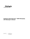
For example purposes the remainder of this manual will use the Q.931 protocol. Q.931 is a
protocol from the CCITT that describes how data and voice calls are setup in an Integrated
2-6
Chapter 2 Quick Start
Services Digital Network (ISDN). Q.931 is a complex protocol with many states, events, and
actions. This makes it an excellent example to show the power of Bayfront CAPE Tools. The
figure below illustrates the generation of all possible output files from this input q931.pdl file.
-s
capedraw q931.s
State Transition Diagram
-se
capedraw q931.se
State/Event Transition Diagram
-sdl
capedraw q931.sdl
SDL Diagram
-i
q931.txt Protocol Information File
-c
q931.h + sm_exec.c + Actions + Primitives
q931.c
-a
q931.act
-n
q931.str State/Event Names File
capegen q931.pdl
Protocol
Implementation
Figure 19. CAPEGen Compiler applied to the Q.931 Protocol
2.5. Using the Bayfront CAPEDraw Viewer (DOS)
Bayfront supports a command line version of the CAPEDraw Viewer when operating under the
DOS operating system. The Bayfront CAPEDraw Viewer uses output files from the Bayfront
CAPEGen Compiler to draw state transition, state/event and Specification and Description
Language (SDL) diagrams. These graphics may be displayed on the screen, displayed on a
printer, or sent to an Adobe PostScript® file for inclusion in protocol documentation by word
processing programs.
Currently the CAPEDraw Viewer is available only under DOS and Microsoft Windows operating
systems. Unix CAPE Tools packages include a DOS version. Unix users wishing to draw and
view diagrams should transfer the PDL files to a PC and convert them to PostScript files. These
can then be viewed using any PostScript Viewer under the Unix operating system.
A state transition, state/event transition or SDL diagram is drawn by a two or three step process.
1.
Invoke the CAPEGen Compiler with the appropriate options (-s, -se and/or -sdl).
2.
Layout the diagram(s) in the file by invoking the CAPEDraw Viewer with the -l option
and the input file name. The resulting file (either .s -> .sd, .se -> .sed, or .sdl > .sdd) contains page layout information for the diagrams. If the protocol is very
complex this layout phase can take some time.
3.
Draw the diagram(s) in the layout files by invoking the CAPEDraw Viewer with the -d
option and the input file name. The diagrams are then drawn by invoking draw with
the appropriate input file name and options. The diagrams may be displayed on the
screen, sent directly to a printer, or sent to a PostScript graphics file. If an SDL layout
file contains more than one diagram, then all of the diagrams are drawn unless the -n
switch selecting a subset of diagrams is specified.
Note that steps two and three may be combined in one command line (e.g., capedraw -l -d
q931.sdl). For files that take a long time to layout and will be displayed in more than one way
(e.g., printer and screen) it is faster to lay out the diagrams in one step and draw them in another.
The figure below illustrates this process.
2-7
Bayfront Technologies CAPE Tools™ Users Manual
Step 1. Generate Pre-layout files with the Bayfront CAPEGen Compiler
-s
capegen q931.pdl
-se
-sdl
q931.s
State Transition Pre-layout File
q931.se State/Event Transition Pre-layout File
q931.sdl SDL Pre-layout File
Step 2. Layout Files
capedraw -l q931.s
q931.sd
capedraw -l q931.se
q931.sed State/Event Transition Draw File
State Transition Draw File
capedraw -l q931.sdl
q931.sdd SDL Draw File
Step 3. Printout and/or display diagrams
capedraw -d -p:PostScript q931.sd
capedraw -d q931.sdd
display state transition diagram
on PostScript printer LPT1
display all SDL diagrams on screen
Figure 20. CAPEDraw Viewer Usage
When the CAPEDraw Viewer displays diagrams on the screen it waits for the user to strike a key
between diagrams. Press the ESC key to escape out of the CAPEDraw Viewer. During the output
of PostScript files the CAPEDraw Viewer draws the current diagram on the screen but does not
wait for the user to strike a key between diagrams.
The CAPEDraw Viewer command line is given below.
capedraw <options> infile.ext <options>
The infile.ext is a diagram file from the CAPEGen Compiler or a layout file from the
CAPEDraw Viewer. The CAPEDraw Viewer options are discussed below.
2-8
-l
Layout all diagrams contained in the input file that was produced by the
CAPEGen Compiler. Creates layout files as follows: state transition
diagrams .s -> .sd, state/event diagrams .se -> .sed, and SDL
diagrams .sdl -> .sdd.
-d
Draw the diagrams contained in the input file that was produced by the
-l option of the CAPEDraw Viewer. If both -l and -d are specified,
then layout is performed before drawing and the input file is expected
to be a CAPEGen Compiler diagram file. Otherwise the input file is
expected to be a CAPEDraw Viewer layout file.
-n:pattern
Only valid if -d is specified. The pattern is matched against the state
names of diagrams held in the layout file. Only diagrams that match
the pattern are output. The pattern consists of literal case insensitive
letters, ? which matches any one character, and * which matches all
remaining characters.
Thus the pattern U0?_* would match
U00_Null and U01_CallInitiated q931 states.
-p:printer
Only valid if -d is specified. This switch requests graphics output to
the printer selected. The supported graphic printer and paper size
choices are shown in the figure below. Some selections produce Adobe
PostScript® files and some send the graphics output to the printer
assumed to be device LPT1: with landscape orientation. The Adobe
PostScript® (.PS) and Encapsulated PostScript output files (.EPS) can
be used by word processors to insert CAPE graphics into documents.
The output graphics file is specified by giving a file name with no
extension (e.g., -p:eps:afile will create the output file
afile.eps).
Chapter 2 Quick Start
-lpt2
Only valid if both -d and -p are specified. This directs the output to
printer port LPT2:. The default printer port is LPT1:.
-nogroup
Only valid if -l is specified. By default similar reference lines in a
diagram are grouped together to form one line. This simplifies the
appearance of complex diagrams. This suppresses the grouping action.
-nopagenum
Only valid if -d is specified. By default the diagram page number is
placed at the bottom right of the diagram. This suppresses the page
number.
-notitle
Only valid if -d is specified. By default the diagram title is placed at
the bottom center of the diagram. This suppresses the title.
-portrait
Only valid if both -d and -p are specified. This indicates that the
diagram is to be oriented with the vertical axis parallel to the longest
paper edge. The default is landscape where the vertical axis is parallel
to the shortest paper edge.
-rotate
Only valid if -d and -p specifies a form of Adobe PostScript® output.
The next section demonstrates the use of -portrait and -rotate
for PostScript output.
1
Adobe PostScript® output is used to prepare documentation graphics and high resolution printer
output. Most word processing programs support the insertion of Encapsulated PostScript (EPS)
graphics with size scaling. Some word processors are unable to rotate the graphic upon insertion.
This requires four orientations to be supported. The figure below shows the four orientations
supported.
dataxfer
WaitAck
Idle
Sending
SetupReceive
WaitAck
dataxfer
Sending
Sending
Receiving
WaitAck
WaitAck
dataxfer
1
default
dataxfer
-portrait
Receiving
SetupReceive
Receiving
Receiving
Sending
SetupSend
Idle
SetupReceive
SetupSend
SetupSend
Idle
SetupReceive
SetupSend
1
Idle
1
-rotate
-portrait
-rotate
Figure 21. Adobe Postscript Output Page Formats
If you are sending your CAPE graphics directly to a PostScript printer that defaults to
printing in the default "portrait" mode you will need to specify the -portrait and rotate options.
2-9
Bayfront Technologies CAPE Tools™ Users Manual
-p:PostScript
-p:PS:<filename>
-p:EPS:<filename>
-p:Epson_FX80_Low
-p:Epson_FX80_Medium
-p:Epson_FX80_High
-p:Epson_FX100_Low
-p:Epson_FX100_Medium
-p:Epson_FX100_High
-p:Epson_LQ850_Low
-p:Epson_LQ850_High
-p:Epson_LQ950_Low
-p:Epson_LQ950_High
-p:Epson_LQ1050_Low
-p:Epson_LQ1050_High
-p:HPLJ_Letter_Low
-p:HPLJ_Letter_Medium
-p:HPLJ_Letter_High
-p:HPLJ_Legal_Low
-p:HPLJ_Legal_Medium
-p:HPLJ_Legal_High
-p:HPPJ_Low
-p:HPPJ_High
PostScript Printer
PostScript File
PostScript EPS File
Epson FX80
Epson FX80
Epson FX80
Epson FX100
Epson FX100
Epson FX100
Epson LQ850
Epson LQ850
Epson LQ950
Epson LQ950
Epson LQ1050
Epson LQ1050
HP Laser Jet II
HP Laser Jet II
HP Laser Jet II
HP Laser Jet II
HP Laser Jet II
HP Laser Jet II
HP Paint Jet
HP Paint Jet
1800x1800 dpi, 8.5"x11.0" paper
1800x1800 dpi, 8.5"x11.0" paper
1800x1800 dpi, 8.5"x11.0" paper
60x 72 dpi, 8.5"x11.0" paper
120x 144 dpi, 8.5"x11.0" paper
240x 216 dpi, 8.5"x11.0" paper
60x 72 dpi, 13.6"x11.0" paper
120x 144 dpi, 13.6"x11.0" paper
240x 216 dpi, 13.6"x11.0" paper
180x 180 dpi, 8.5"x11.0" paper
360x 360 dpi, 8.5"x11.0" paper
180x 180 dpi, 11.0"x11.0" paper
360x 360 dpi, 11.0"x11.0" paper
180x 180 dpi, 13.6"x11.0" paper
360x 360 dpi, 13.6"x11.0" paper
100x 100 dpi, 8.5"x11.0" paper
150x 150 dpi, 8.5"x11.0" paper
300x 300 dpi, 8.5"x11.0" paper
100x 100 dpi, 8.5"x13.0" paper
150x 150 dpi, 8.5"x13.0" paper
300x 300 dpi, 8.5"x13.0" paper
90x 90 dpi, 8.5"x11.0" paper
180x 180 dpi, 8.5"x11.0" paper
Figure 22. Graphic Printers and Formats Supported by the CAPEDraw Viewer
2-10
Chapter 3 Protocol Definition Language
3. Protocol Definition Language (PDL)
3.1. Overview
The purpose of the Protocol Definition Language (PDL) is to define the essential structure of a
protocol without becoming mired in the details of a particular programming language. Since the
PDL definition is used to generate code, diagrams, analysis reports, and simulations we have
attempted to remove elements specific to one of these areas from the language. When there are
options related to these different processes, they are specified when the process is invoked.
3.2. PDL Elements
Most protocol layers are composed of one or more state machines. The state machines of the
protocol layer may enable, disable, and interact with each other. They share the data and queue
definitions for the layer. With this understanding the primary unit of definition in PDL is the
state machine. The figure below presents a simple PDL definition.
[ example protocol state machine
multiline comments in brackets ]
sm1 { InitialState = State1;
state State1::
Event1 -> Action1, Action2 >> State2;
[ goes to State1])
Event2 -> Action3;
Event3 |
[ Event3 or Event4 ]
Event4 -> Action2 >> State2;
default -> Action7;
[ any other events ]
state State2::
Event1-> Action4;
Event2-> Action5, Action6 >> State1;
}
Figure 23. Example PDL Definition
In the above figure the reserved words and punctuation are shown in bold. The name of the
protocol layer state machine sm1 is given first followed by the definition of the initial state of the
protocol.
3.2.1. Spacing, Comments and Syntax Diagrams
The fields of a PDL definition do not have to be aligned. It is a good idea to align the fields to
make the definition easier to read. Whitespace which includes spaces, tabs, carriage returns, line
feeds, and form feeds may be freely inserted anywhere a single space is accepted. Whitespace is
accepted between all keywords, punctuation, identifiers, and numbers.
Comments are enclosed in square brackets ([]).
included anywhere spaces are accepted.
They may contain multiple lines and be
In the syntax diagrams given below the reserved words and punctuation are shown bolded in
ovals. The invocation of another syntax diagram is shown by a rectangle labeled with the
diagram name. Some single character syntax diagrams are not shown. numeral stands for any
one numeral character 0 through 9. alphabetic stands for any one upper or lower
alphabetic character A through Z and a through z. underscore stands for the underscore
character _. No whitespace is allowed between these single character syntax diagrams.
3-1
Bayfront Technologies CAPE Tools™ Users Manual
3.2.2. Identifiers
Identifiers used in PDL definitions are a maximum of 36 characters long.
Identifier
alphabetic
alphabetic
underscore
numeral
underscore
Figure 24. Identifier
The identifiers must not conflict with the reserved words of PDL. This check is case insensitive
to allow for the generation of code in case insensitive languages. The reserved words include:
action
deallocate
inc
resetflag
setvalue
Stop
TimerRunning
allocate
deassign
InitialState
RestartTimer
signal
Timer
assign
dec
macro
send
StartTimer
State
Figure 25. PDL Reserved Words
3.2.3. Numbers
Numbers in PDL are unsigned integers with the usual syntax.
Figure 26. Numbers
These are used to pass constants to user supplied routines in actions.
3-2
break
event
recv
setflag
StopAllTimers
timeout
Chapter 3 Protocol Definition Language
3.3. PDL Structure
protocol state machine
{
identifier
initial state
}
state
event macro
action macro
Figure 27. PDL Structure Syntax
The basic structure of a PDL definition identifies and defines the protocol state machine and
context. The initial identifier provides the state machine name.
initial state
InitialState
=
identifier
;
Figure 28. PDL Initial State Syntax
The initial state rule identifier provides the beginning state when the protocol state machine is
enabled. The rest of the definition is a series of state definitions. The optional macro definitions
at the end of the state definitions are a convenient shorthand for specifying repetitive parts of the
protocol definition. Notice that the entire set of state and macro definitions must be enclosed in
set braces {}.
3.4. States
state
state
identifier
::
events
Figure 29. PDL State Syntax
A state definition starts with the reserved word state and an identifier that names the state.
The set of events that follow specify the events that are handled by the state machine in this state.
Each event specifies what triggers the particular event, what actions are to be taken, and what
state transition (if any) to make after taking those actions. Within a state all of the event triggers
must be mutually exclusive. This means that one outside stimulus can never trigger two state
events. If an event is not handled in a state, then no actions are taken and no state transition
takes place.
3-3
Bayfront Technologies CAPE Tools™ Users Manual
3.5. Events
events
macro
;
identifier
event trigger
->
actions
Figure 30. PDL Event Syntax
Each event specifies the set of triggers for a transition in the state machine. The actions to take
upon this transition are also specified. Transition to a new state in the state machine may be
specified as the final action in the actions. An event macro is just a convenient way to specify
the same information under the given macro name. Event macros are specified after all state
definitions.
The external events that moves the state machine along are specified as event triggers.
event trigger
identifier
recv
(
timeout
identifier
(
identifier
,
identifier
)
|
)
Figure 31. PDL Event Trigger Syntax
The basic event forms may be combined into a trigger using a logical or (|) to mean that any one
of the given events triggers the actions to be taken.
3-4
identifier
This name is the name of an external user indicated event.
This is the name of an external event that the user-written
event processor will use to signal to the Bayfront-supplied
state machine executor that the external event has occurred.
This allows the user to completely define the external events
and control the protocol state machine transitions.
recv(message,queue)
This event is indicated when a message of the given type is
received on the given queue, stream, or mailbox. The
indicating constant for this event is named as
"rqueue_message" on code generation. As an example the
PDL event recv(AbortMsg,Net) would be indicated as
the named constant rNet_AbortMsg to the state machine
executor.
Chapter 3 Protocol Definition Language
timeout(timer)
This event is indicated when the given timer expires. The
event is renamed to "timer_timeout" on code generation.
Thus the event timeout(AckTimer) would be indicated as
the named constant ActTimer_timeout.
recv(default,queue)
This event is indicated when any message type except the ones
specifically
defined
for
this
state
via
the
recv(message,queue) event have been received on the
given queue, stream, or mailbox. An event processor does not
explicitly indicate this event with a named constants as it does
for the above three event types. Instead the event processor
implicitly indicates this event by indicating any explicit recv
message event for the given queue that is not used in any
trigger in this state.
timeout(default)
This event is indicated when any timer timeout is ending
except those timeouts specifically defined in this state. An
event processor does not explicitly indicate this event. Instead
the event processor implicitly indicates this event by indicating
any explicit timeout event that is not used in any trigger in
this state.
default
This event is indicated when any external user indicated event
is pending that is not explicitly part of any trigger in this state.
This cannot serve as a default event for timeout and recv
events. The above two event types serve that purpose. There
does not have to be a default trigger. An event processor does
not explicitly indicate this event. Instead the event processor
implicitly indicates this event by indicating any explicit
external user indicated event that is not used in any trigger in
this state.
If in a given state an event is indicated that is not part of any trigger, then no actions are
performed. An example would be a message MsgType arriving on a queue MsgQueue. If this
case is not handled explicitly (e.g., recv(MsgType,MsgQueue)) or implicitly (e.g.,
recv(default,MsgQueue)), then no actions are performed and no state transition occurs.
3.6. Event Macros
Event macros are an efficient shorthand for specifying repetitive events that appear in many
states. An example would be the "disconnect request received go to the idle state" kind of
operation. The shorthand is invoked by the keyword macro and the name. The event macros
are defined after all of the states have been specified.
event macro
event
macro
identifier
:
events
Figure 32. PDL Event Macro Syntax
The single macro identifier can expand to one or more event trigger to action sequences. Event
macros cannot be nested. The meaning of the macro is as if the macro was expanded directly for
its name. If an action causes a transition to the same state, then the state is the state where the
macro usage occurred.
3-5
Bayfront Technologies CAPE Tools™ Users Manual
3.7. Actions
Actions modify the protocol execution environment as the state machine makes transitions from
state to state.
actions
>>
action
identifier
,
macro
identifier
Figure 33. PDL Actions Syntax
Each event can trigger zero or more actions. More than one action is separated by commas.
Optionally the last action in an action sequence can cause a transition to another state. The >>
syntax with a state identifier requests the transition to that state. If no transition action is
performed, then the state machine remains in the same state. As with event macros an entire set
of actions for an event trigger including a state transition may be specified as an action macro.
The action macro invocation may follow some actions particular to a state/event pair.
Most individual actions call user supplied routines. Some kinds of actions, like message sending,
are identified by syntax to isolate concepts needed to analyze the protocol.
action
break
send
(
identifier
,
identifier
)
identifier
external arguments
switch action
Figure 34. PDL Action Syntax
The break action is only legal in the context of a switch action.
3.7.1. Actions on Timers and Messages
The keywords RestartTimer, send, StartTimer, StopAllTimers, StopTimer,
and TimerRunning identify certain actions and ultimately call user supplied routines.
send(message,queue)
3-6
This action generates a call to the user supplied routine
called "squeue_message". As an example the PDL action
send(Release,Net) would call the user-supplied
routine sNet_Release with context. This routine is
responsible for assembling the message using context
information and putting it on the given queue.
Chapter 3 Protocol Definition Language
StartTimer(timer)
This action generates a call to the user supplied routine
called StartTimer with a generated timer code as an
argument. The routine starts the given timer.
StopTimer(timer)
This action generates a call to the user supplied routine
called StopTimer with a generated timer code as an
argument. The routine stops the given timer.
RestartTimer(timer)
This action generates a call to the user supplied routine
called RestartTimer with a generated timer code as an
argument. The routine restarts the given timer.
StopAllTimers
Generates a call to the user-supplied routine
StopAllTimers that stops all timers defined for the
state machine.
TimerRunning(timer)
Calls the user supplied routine TimerRunning with a
generated timer code. The routine returns one of the
defined values YesRunning or NoRunning whether or
not the timer is running. This action is used in switch
actions to be discussed later.
3.7.2. Action Calls to User Routines
The identifier acceptable as an action refers to a user-supplied action routine with the same
name. These routines may be passed arguments as shown below.
external arguments
number
(
)
,
identifier
Figure 35. PDL External Routine Argument Syntax
The external argument number refers to an unsigned 16 bit integer. The external argument
identifier refers to user supplied variables in the protocol execution environment that may
be manipulated by user supplied action routines.
3.7.3. Switch Actions
Many times the protocol state machine is controlled by environmental conditions not available in
the state machine context. To test these conditions we use a switch action. In the action
syntax diagram a switch action is preceded by an identifier giving the name of an user
supplied external routine and optionally external arguments. In a switch action a value
returned by the user routine is tested. The call to the user routine is followed by the switch/case
syntax below.
action macro
action
macro
identifier
:
actions
;
Figure 36. PDL Switch Action Syntax
3-7
Bayfront Technologies CAPE Tools™ Users Manual
There are a series of identifier and action pairs. The identifier stands for a discrete value
constant that is returned by the user routine. The actual value is defined by the code generator.
The actions associated with the given return value are called by the state machine executor.
A switch action appears in a PDL definition as follows:
check_msg {
msg_ok -> ... ;
msg_too_small -> ... ;
msg_too_large -> ... ;
msg_format_error -> ... ; }
In this example check_msg is a user-supplied action routine that returns the switch return
names msg_. The restrictions on switch return names include:
1.
Return names must be unique to the specific switch statement. For example if the switch
statement check_msg returns the value msg_ok, then no other switch statement except
check_msg can use the name msg_ok.
2.
Switch functions must return the same number of switch return values each place the
function is called. For example if the switch statement check_msg returns four switch
return
values,
and
msg_ok,
msg_too_large,
msg_too_small,
msg_format_error, then all instances of check_msg must return these four switch
return values.
Notice that this syntax is recursive on the actions rule. The break keyword syntax may
only be used inside the context of a switch action. It causes execution to continue with the action
after the enclosing switch action.
3.8. Action Macros
Action macros are an efficient shorthand for specifying a complete list of actions and state
transitions. An action macro invocation may be used anywhere actions are expected. This
includes after event triggers in events and inside of an switch action. As with
event macros, action macros are treated as if they were expanded where they are invoked. They
are very efficient in execution with minimum calling overhead.
Action macros are defined with event macros after all states have been defined. Their definitions
have the following syntax.
action macro
action
macro
identifier
:
actions
;
Figure 37. PDL Action Macro Syntax
Action macro definitions may not be nested.
3.9. Error Recovery and Reporting
If a syntax error occurs during the parsing of a PDL program, a syntax error will be reported and
the parser will attempt to recover and report more errors (DOS/Unix) or the parsing will halt and
the cursor will be positioned at the error in the PDL edit window (Windows). Semantic errors
are analyzed after the syntax has been parsed. Any kind of error will inhibit the creation of
output files. The errors reported by the CAPEGen Compiler are given in Appendix A.
3-8
Chapter 3 Protocol Definition Language
3.10. PDL Example
The PDL definition illustrated below uses many linguistic constructs available in a PDL
definition.
[The following example illustrates many of the syntax features of the pdl. ]
ex_ch3 { InitialState = S1;
state S1::
E1 -> sw1 { [switch action]
rtn1 -> A1, break;
rtn2 -> A2, A3 >> S2;
rtn3 -> A4, macro MA5;
rtn4 -> ;
}, A6 >> S2;
E2 -> sw2(p1,10) {
rtn5 -> break;
rtn6 -> A7 >> S1;
}, A7 >> S2;
E3 -> ;
[after A1 execute A6 below]
[execute A4, goto action macro MA5]
[no actions triggered, return]
[action after sw1 switch action]
[switch action with passed parameters]
[exit sw2 and execute A7 below]
[no actions are triggered]
state S2::
macro ME12;
[go to macro ME12 below]
E3 -> A11, A12(p1, p2), A13, A14 >> S1;
[note: only action macros can be called within an event macro]
event macro ME12:
E1 |
[trigger on event E1 or E2]
E2 -> A8, macro MA5;
[execute A8, goto action macro MA5]
[note: no other macros can be called within an action macro]
action macro MA5:
A9, A10;
[execute actions A9 & A10, no state change]
}
Figure 38. PDL Syntax Example
Notice that the example above uses an action macro inside of an event macro.
3.11. PDL Restrictions
A summary of the language restrictions is given below.
1.
2.
3.
4.
5.
6.
7.
8.
Event macro definitions may not be nested.
Action macro definitions may not be nested.
The break action is only legal inside the context of a switch action.
All switch actions based on the same user supplied function must handle the same result
cases.
There can only be one default event for a state. Although a state definition may
contain one each of default, recv(default,queue), and timeout(default).
There can be only one recv(default,queue) event in a state for each queue used in
the state machine.
There can be only one timeout(default) event for a state.
An event not included in any trigger in a state performs no operation when indicated by
the event processor in that state.
3-9
Bayfront Technologies CAPE Tools™ Users Manual
3-10
Chapter 4 C Code Files
4. C Code Files
4.1. Overview
The CAPEGen Compiler generates two files when the capegen -c option (DOS/Unix) or the
Options|Compile|C Code Generation File menu options (Windows) are selected.
These files include the state machine header file (.h) and the protocol state machine table file
(.c). These files are generated from the input PDL file and are compilable by an ANSI C
compiler. The figure below illustrates the process of constructing a protocol implementation.
Protocol
Specification
Protocol
Definition
File
(PDL)
Options:
C Code
State Machine
State + Executor
+ Actions + Primitives
Tables
-c (DOS/Unix)
Bayfront
CAPEGen
Compiler
Options|Compile|
C Code
File
(Windows)
-a (DOS/Unix)
Protocol
Implementation
Action Prototype File
Options|Compile|
Action Prototype File
(Windows)
User Supplied Information or Routines
Figure . C Code Table File Generation
The state tables are used to drive the Bayfront-supplied state machine executor (sm_exec.c).
When the state machine table file is linked with the Bayfront-supplied state machine executor
(sm_exec.c), the user-supplied actions, the user-supplied event handler and the user-supplied
operating system primitives, a protocol implementation results.
The figure below describes the architecture of the resulting protocol implementation.
4-1
Bayfront Technologies CAPE Tools™ Users Manual
Events to
Operating System
Events from
Operating System
State Tables
Event
State Machine
Processor
Executor
Action
Primitive
Action
Primitive
Action
Primitive
Action
Primitive
Action
Primitive
Figure 40. Protocol Layer Architectural Model
This architecture is discussed in detail in Chapter 1. Briefly a user-written event processor
stimulates the state machine executor with external events (e.g., received messages, timeouts,
interrupts, etc.). The state machine executor is supplied by Bayfront Technologies in source form
and is discussed in Chapter 5. The state machine executor implements a protocol state machine
by interpreting state tables output by the CAPEGen Compiler. There is at least one set of state
tables for each protocol state machine in each communications layer, realtime process or
client/server module. Also for each state machine there is a set of user-written actions. These
actions affect the operating environment through user-written primitives.
For explanation purposes we will be using the protocol definition file q931.pdl which is
included in the examples directory of the Bayfront CAPE Tool product disk. The name of this
PDL state machine is q931. Invoking capegen with the -a option (DOS/Unix) or the
Options|Compile|Action Prototype File menu options (Windows) on q931.pdl
results in the generation of the action prototype file (q931.act) which is discussed in Chapter
6. Invoking capegen with the -c option (DOS/Unix) or the Compiler/Options/Code
Generation File on q931.pdl results in two files: the protocol/state machine header file
(q931.h) and the protocol/state machine table file (q931.c). The contents of these files will
be discussed in the remaining sections of this chapter. All of these files are shown in their
entirety in the CAPE Tools examples directory.
This chapter presents an interpretive approach to protocol implementation that minimizes space
instead of execution time. It is Bayfront Technologies experience that the most important part of
systems design and implementation is to get the protocol to work and then optimize.
Optimization should only be directed toward the 10% of the code that is executed 90% of the
time. In the architecture presented in Chapter 1 this "inner loop" will be located in the usersupplied event processor, actions, or primitives. Optimize the primitives first the actions second
and the event processor third. Optimizing the entire design leads to individual designer
"craftsman" efforts that are inflexible and hard to maintain by anyone except the original author.
4.2. Protocol/State Machine Header File Contents
The header file produced for a protocol state machine (.h) contains the following definitions:
1.
2.
3.
4.
5.
4-2
protocol state definitions
protocol event definitions
timers (if defined in the PDL file)
switch action return values
external action function declarations
Chapter 4 C Code Files
Each of these header file definitions are discussed in the sections below.
4.2.1. State Definitions
Constants for all the states contained in the PDL file are defined alphabetically in the state
machine header file.
/* ---- States ---- */
#define U00_Null 0
#define U01_CallInitiated 1
#define U02_OverlapSending 2
#define U03_OutgoingCallProc 3
#define U04_CallDelivered 4
#define U06_CallPresent 5
#define U07_CallReceived 6
#define U08_ConReq 7
#define U09_IncomingCallProc 8
#define U10_Active 9
#define U11_DiscReq 10
#define U12_DiscInd 11
#define U15_SuspendReq 12
#define U17_ResumeReq 13
#define U19_ReleaseReq 14
#define U25_OverlapReceiving 15
#define q931_MaxStates 16
#define q931_InitialState U00_Null
Figure 41. State Definitions from q931.h
Users should include this file when coding their user-supplied event processor, actions, and
primitives. User-supplied codes should only refer to the states by name since a change to the
PDL definition could change the underlying values.
The maximum number of states is defined as q931_MaxStates. The state machine structure
uses the maximum states definition to check for out of bounds states during the execution of the
protocol/state machine (see file sm_exec.c).
The initial state name is defined as q931_InitialState. The initial state name is used to
initialize the state machine. The current state is kept in the context block which is discussed in
Chapter 5.
4.2.2. Event Definitions
All events contained in the PDL file are listed alphabetically in the state machine header file.
The user-supplied event processor, actions, and primitives should include the header file and
refer to the events by name.
It is the function of the user-supplied event processor (see architecture in Chapter 1) to translate
an incoming operating system event into one of the event definitions in the header file before
calling the state machine executor (sm_exec). As discussed in Chapter 3 some events are
renamed from their PDL definitions (e.g., recv(Alerting,net) becomes
rnet_Alerting). The events for q931 are shown below.
/* ---- Events ---- */
#define T302_timeout 0
#define T303_timeout 1
#define T304_timeout 2
#define T305_timeout 3
#define T308_timeout 4
#define T309_timeout 5
4-3
Bayfront Technologies CAPE Tools™ Users Manual
#define T310_timeout 6
#define T313_timeout 7
#define T318_timeout 8
#define T319_timeout 9
#define rnet_Alerting 10
#define rnet_CallProc 11
#define rnet_ConAck 12
#define rnet_Connect 13
#define rnet_DL_Est_Conf 14
#define rnet_DL_Est_Ind 15
#define rnet_DL_Rel_Ind 16
#define rnet_Disc 17
#define rnet_Info 18
#define rnet_Notify 19
#define rnet_Progress 20
#define rnet_Release 21
#define rnet_ReleaseComp 22
#define rnet_ResumeAck 23
#define rnet_ResumeRej 24
#define rnet_SetUp 25
#define rnet_SetUpAck 26
#define rnet_Status 27
#define rnet_StatusEnquiry 28
#define rnet_SuspendAck 29
#define rnet_SuspendRej 30
#define rnet_UnrecognizedMsg 31
#define ruser_AlertingReq 32
#define ruser_DiscReq 33
#define ruser_InfoReq 34
#define ruser_MoreInfoReq 35
#define ruser_NotifyReq 36
#define ruser_ProcReq 37
#define ruser_ProgressReq 38
#define ruser_RejReq 39
#define ruser_ReleaseReq 40
#define ruser_RestartReq 41
#define ruser_Resume 42
#define ruser_SetUp 43
#define ruser_SetUpRsp 44
#define ruser_SuspendReqcallid 45
#define q931_MaxEvents 46
Figure 42. Event Definitions from q931.h
The figure above illustrates that the q931 events all come from only three sources: timeouts,
messages from the net queue, and messages from the user queue. There are no user defined
custom events.
4.2.3. Timer Defines
Timer definitions are created from the appearance of the special actions StartTimer,
StopTimer and StopAllTimers. As with state and event definitions, user routines that deal
with timers should include the header file and only refer to timers by their defined names. The
user-supplied action routines such StartTimer and StopTimer take the timer as a passed
parameter.
/* ---- Timer Defines ---- */
#define T302 0
#define T303 1
4-4
Chapter 4 C Code Files
#define T304 2
#define T305 3
#define T308 4
#define T309 5
#define T310 6
#define T313 7
#define T318 8
#define T319 9
Figure 43. Timer Definitions from q931.h
4.2.4. Switch Action Return Values
Switch action return defines are the values returned from the PDL switch actions. The state
machine executor (sm_exec.c) performs a runtime bounds check on the return value every
time the switch action is called. Out of bounds return values will cause the sm_exec to
immediately return to the caller with a value indicating an out of bounds condition (see state
machine executor discussion in Chapter 5). In the q931.h example the switch action
ActOption returns only two values, YesAck with a value of 0 and NoAck with a value of 1.
Users should code the ActOption action function by including the header file and using the
YesAck and NoAck definitions to return one of these two values.
/* ---- Switch Labels ---- */
/* 'AckOption' return values */
#define YesAck 0
#define NoAck 1
/* 'AnyTimersRunning' return values */
#define NoTimersRunning 0
#define YesTimersRunning 1
/* 'CSZeroNonZero' return values */
#define CSZero 0
#define CSNonZero 1
/* 'CauseOption' return values */
#define C1 0
#define C2 1
/* 'CheckSetUpMsg' return values */
#define SetUpOk 0
#define SetUpManElementMissing 1
#define SetUpManElementError 2
/* 'CheckStatusCsField' return values */
#define CsZero 0
#define CsNotZero 1
/* 'CompatibleStateCheck' return values */
#define YesCompatible 0
#define NoCompatible 1
/* 'DLOption' return values */
#define DLStatusOpt 0
#define DLStatusEnqOpt 1
#define DLDefaultOpt 2
/* 'DLRelOption' return values */
#define NullOption 0
#define NoNullOption 1
/* 'FirstTimeOut' return values */
4-5
Bayfront Technologies CAPE Tools™ Users Manual
#define YesFirst 0
#define NoFirst 1
/* 'ProgressType' return values */
#define InterNetworking 0
#define Tone 1
/* 'RejectOption' return values */
#define YesReject 0
#define NoReject 1
/* 'RelOption' return values */
#define RelOpt 0
#define RelCompOpt 1
/* 'StatusEnqOption' return values */
#define YesEnqOption 0
#define NoEnqOption 1
/* 'TimerRunning' return values */
#define YesRunning 0
#define NoRunning 1
/* number of unique switch labels = 32 */
Figure 44. Switch Function Return Values from q931.h
4.2.5. External Action Function Declarations
The external action declarations refer to the user-supplied protocol or state machine actions. All
actions except switch actions should return a value of one to indicate successful completion.
Actions that return a value other than one cause the state machine executor to quit triggering the
actions and return to the event processor. See Chapter 5 for more details. All actions are passed
an Event Control Block pointer whose type is user defined, e.g., void. For more information on
the possible structure of this type see Chapter 5.
/* ---- Action Subroutine Declarations ---- */
extern int AckOption();
extern int AnyTimersRunning();
extern int BChanMaintenance();
extern int CSZeroNonZero();
extern int CallRefSelection();
extern int CauseOption();
extern int CheckSetUpMsg();
extern int CheckStatusCsField();
extern int CompatibleStateCheck();
extern int DLOption();
...
extern int suser_StatusInd();
extern int suser_SuspendConf();
extern int suser_TimeoutInd();
Figure 45. Portion of External Action Prototypes from q931.h
4.3. Protocol/State Machine Table File Contents
The state machine table file (.c) contains structures and tables used by the state machine
executor (sm_exec.c, see Chapter 5). We will continue using q931.pdl as an example. The
information in the following sections comes from q931.c which can be found in the Bayfront
CAPE Tool™ product disk under the examples directory.
4-6
Chapter 4 C Code Files
The user does not have to know about the inner workings of this file or the interaction
between this file and the state machine executor to implement protocols or state machines.
The information in this section is included for users who wish to know how the protocol state
machine is implemented.
4.3.1. Include files
The state machine table file, q931.c includes both the Bayfront CAPE Tools header file,
cape.h, and the state machine header file q931.h (see previous section). The cape.h file
(see Figure below) contains structure prototypes used to define the state machine such as SWTBL
(switch table), AAEntry (action table entry), and SM (state machine structure). The PDL header
file contains necessary defines such as the number of states and events in the protocol definition.
4.3.2. Action Parameter Definitions
The action parameter definition section of the q931.c file contains all non-numeric action
parameters except the user defined Event Control Block pointer pECB parameter.
/* ---- action parameter definitions ---- */
int error; /* ?type? from action: 'suser_SetUpCompInd' */
int ok;
/* ?type? from action: 'suser_SetUpCompInd' */
Figure 46. Action Parameter Definitions
The parameter types are defaulted as integers and will contain the /*?type?*/ comment as a
reminder these types were defaulted to integers and can be changed. Also contained in the
comment will be the last action that uses this parameter. The user may change these parameters
as necessary. Use caution. Modifications of q931.c will be lost if the CAPEGen Compiler
code generation option -c is used to regenerate this file.
4.3.3. Switch Return Value Table and the Switch Table
The switch table is an array of tuples each containing an index into the switch return value table
and the number of switch return values defined for this switch statement. Both tables as
generated from the q931.pdl are shown below.
/* Indices into the q931_SwLblVect array, # of return values */
static SWTBL q931_SwTbl[] = {
{0, 2},
{2, 2},
{4, 2},
{6, 2},
{8, 2},
{10, 2},
{12, 2},
{14, 2},
{16, 2},
{18, 3},
{21, 3},
{24, 2},
{26, 2},
{28, 3},
{31, 2},
{33, 2},
{35, 2},
{37, 2},
{39, 2},
{41, 2},
{43, 2},
4-7
Bayfront Technologies CAPE Tools™ Users Manual
{45, 2},
{47, 2},
{49, 2},
};
Figure 47. Switch Table from q931.c
/* Switch Return Value Table (indices into the Action Vector Table) */
static int q931_SwLblVect[] = {
106, 107,
/* 'AckOption' */
96, 97,
/* 'AckOption' */
73, 74,
/* 'AckOption' */
55, 56,
/* 'AckOption' */
247, 248,
/* 'AnyTimersRunning' */
250, 252,
/* 'CSZeroNonZero' */
190, 191,
/* 'CSZeroNonZero' */
272, 273,
/* 'CauseOption' */
234, 235,
/* 'CauseOption' */
9, 12, 13, /* 'CheckSetUpMsg' */
5, 6, 7,
/* 'CheckSetUpMsg' */
15, 16,
/* 'CheckStatusCsField' */
253, 254,
/* 'CompatibleStateCheck' */
240, 241, 242, /* 'DLOption' */
244, 246,
/* 'DLRelOption' */
184, 186,
/* 'FirstTimeOut' */
46, 48,
/* 'FirstTimeOut' */
67, 69,
/* 'ProgressType' */
114, 115,
/* 'RejectOption' */
24, 26,
/* 'RelOption' */
17, 19,
/* 'RelOption' */
270, 271,
/* 'StatusEnqOption' */
232, 233,
/* 'StatusEnqOption' */
59, 60,
/* 'TimerRunning' */
};
Figure 48. Switch Return Value Table from q931.c
For example the first entry {0, 2} in the switch table indicates that in the zero position of the
switch return value table the AckOption switch returns two values. Referring to the switch
return value table if AckOption returns YesAck (value 0) the tuple in the action array starting
at 106 will be executed and if AckOption returns NoAck (value 1) the tuple in the action
array starting at 107 will be executed.
4.3.4. Action Routines that Pass Parameters
All actions that pass parameters other than the Event Control Block pointer pECB are indirectly
called due to ANSI C language limitations. Indirectly calling the actions allow the passed
parameters to be included in the action call. The user-supplied timer operations are an example
of an action routine that takes a parameter because they must be passed the timer and pECB . All
parameters other than the pECB are defaulted as integers.
/* ---- Action routines which pass arguments ---- */
int FirstTimeOutT308(pECB)
void *pECB;
{ return(FirstTimeOut(T308,pECB)); }
int RestartTimerT304(pECB)
void *pECB;
{ return(RestartTimer(T304,pECB)); }
int StartTimerT309(pECB)
4-8
Chapter 4 C Code Files
void *pECB;
{ return(StartTimer(T309,pECB)); }
int snet_Release0(pECB)
void *pECB;
{ return(snet_Release(0,pECB)); }
int snet_ReleaseComp100(pECB)
void *pECB;
{ return(snet_ReleaseComp(100,pECB)); }
int suser_SetUpCompIndok(pECB)
void *pECB;
{ return(suser_SetUpCompInd(ok,pECB)); }
Figure 49. Portion of Action Routines that Pass Parameters from q931.c
4.3.5. State/Event To Action Array Jump Table
This composite structure is a two dimensional array which is indexed by the State and Event.
The entries of the state/event table contains numbers which are indices into the action array table.
Given the state and the event these tables provide the index for the next action list to perform in
the action array table.
static int *q931_StateEvent[] = {
q931_U00_Null,
q931_U01_CallInitiated,
q931_U02_OverlapSending,
q931_U03_OutgoingCallProc,
q931_U04_CallDelivered,
q931_U06_CallPresent,
q931_U07_CallReceived,
q931_U08_ConReq,
q931_U09_IncomingCallProc,
q931_U10_Active,
q931_U11_DiscReq,
q931_U12_DiscInd,
q931_U15_SuspendReq,
q931_U17_ResumeReq,
q931_U19_ReleaseReq,
q931_U25_OverlapReceiving
};
Figure 50. State/Event Table from q931.c
/* ---- q931 Action Vector Jump Table [MaxStates][MaxEvents] ---- */
static int q931_U00_Null[] = {
23, 23, 23, 23, 23, 31, 23, 23, 23, 23, 23, 23, 23, 23, 30,
23, 29, 23, 23, 23, 23, 20, 22, 23, 23, 4, 23, 14, 27, 23,
23, 23, 23, 23, 23, 23, 23, 23, 23, 23, 23, 28, 1, 8, 23,
23
};
static int q931_U01_CallInitiated[] = {
212, 45, 212, 212, 212, 226, 212, 212, 212, 212, 50, 42, 212, 52, 225,
227, 224, 212, 212, 212, 212, 212, 39, 212, 212, 214, 36, 217, 216, 212,
212, 213, 212, 33, 32, 212, 212, 212, 212, 212, 212, 215, 212, 212, 212,
212
};
static int q931_U02_OverlapSending[] = {
212, 212, 78, 212, 212, 88, 212, 212, 212, 212, 64, 61, 212, 70, 87,
83, 84, 212, 81, 212, 66, 221, 220, 212, 212, 214, 212, 217, 216, 212,
212, 213, 212, 82, 57, 212, 212, 212, 212, 212, 75, 215, 212, 212, 212,
4-9
Bayfront Technologies CAPE Tools™ Users Manual
212
};
static int q931_U03_OutgoingCallProc[] = {
212, 212, 212, 212, 212, 226, 98, 212, 212, 212, 91, 212, 212, 93, 225,
227, 224, 222, 219, 212, 89, 221, 220, 212, 212, 214, 212, 217, 216, 212,
212, 213, 212, 223, 218, 212, 212, 212, 212, 212, 101, 215, 212, 212, 212,
212
};
static int q931_U04_CallDelivered[] = {
212, 212, 212, 212, 212, 226, 212, 212, 212, 212, 212, 212, 212, 104, 225,
227, 224, 222, 219, 212, 212, 221, 220, 212, 212, 214, 212, 217, 216, 212,
212, 213, 212, 223, 218, 212, 212, 212, 212, 212, 212, 215, 212, 212, 212,
212
};
Figure 51. Portion of the Action Array Jump Table from q931.c
4.3.6. Action Vector Table
This structure is an vector of tuples containing the actions to be triggered upon specific
state/event occurrences. It is indexed by the state/event table of the previous section.
/* ---- Action Vector Table ---- */
static AAEntry q931_ActArray[] = {
/* Null Entry */ {0, 0, 0}, /* fcn, type, jmp or newstate */
/* Action 1 */ {CallRefSelection, 1, 521},
/* Action 2 */ {snet_Resume, 1, 521},
/* Action 3 */ {StartTimerT318, 5, 13},
/* Switch 4 */ {CheckSetUpMsg, 3, 10},
/* Action 5 */ {suser_SetUpInd, 1, 5},
/* Action 6 */ {snet_ReleaseComp96, 5, 520},
/* Action 7 */ {snet_ReleaseComp100, 5, 520},
/* Switch 8 */ {CheckSetUpMsg, 3, 9},
/* Action 9 */ {CallRefSelection, 1, 521},
/* Action 10 */ {snet_SetUp, 1, 521},
/* Action 11 */ {StartTimerT303, 5, 1},
/* Action 12 */ {snet_ReleaseComp96, 5, 520},
/* Action 13 */ {snet_ReleaseComp100, 5, 520},
/* Switch 14 */ {CheckStatusCsField, 3, 11},
/* Action 15 */ {0, 2, 520},
/* Switch 16 */ {RelOption, 3, 20},
/* Action 17 */ {snet_Release101, 5, 521},
/* Action 18 */ {StartTimerT308, 5, 14},
Figure 52. Portion of the Action Vector Table in q931.c
Each tuple contains three fields. One field contains the action to call or a zero for a null action
(i.e., state change without action) or goto action/event macro call. Another field contains the
type of tuple. The final field contains the new state transition or an indication of the jump index.
4.3.7. State Machine Definition Structure
This structure ties together all the structures in the state machine table file (q931.c).
/* ---- q931 state machine definitions ---- */
SM q931 = {
q931_MaxStates,
/* max states */
q931_MaxEvents,
/* max events */
q931_ActArraySize,
/* # of entries in the action array */
q931_SwLblVect,
/* Switch return value ActArray indicies */
q931_SwTbl,
/* SwLblVect index & # of rtn values */
4-10
Chapter 4 C Code Files
q931_StateEvent,
q931_ActArray
/* state/event to action vector tbl */
/* action vector table */
};
Figure 53. State Machine Definition Structure in q931.c
This structure contains the maximum number of states, maximum number of events, the action
array size, a pointer to the switch return value and the switch tables, a pointer to the state/event
to action array vector table and a pointer to the action array. A pointer to this structure is passed
to the state machine executor (sm_exec). See Chapter 5 for an example call from the usersupplied event processor to the state machine executor.
4.3.8. Interrelations Between Generated Structures
In this chapter we have discussed as an example the static structures in q931.c generated by the
Bayfront CAPEGen Compiler -c option parsing q931.pdl. The pointer and index
relationships between these structures is shown below.
Q.931
Info
q931_StateEvent
q931_state
q931_SwLblVect
q931_SwTbl
YesOrNoSwitch
2 results
states
dimension
Yes
No
events dimension
(traditional jump table, jump to actions)
q931_ActArray
function
type
state or
action
TimeOutT308
user routines
with parameters
Figure 54. Relationships between Generated q931 Structures
The table below identifies the C Code structures with the q931 structure names.
C Code Structure
Switch Table
Switch Return Value Table
Action Routines w/Params
State/Event Table
Action Array Jump Table
Action Vector Table
State Machine Definition
q931 Structure Name
q931_SwTbl
q931_SwLblVect
func FirstTimeOutT308
q931_StateEvent
q931_state
q931_ActArray
q931
4-11
Bayfront Technologies CAPE Tools™ Users Manual
4-12
Chapter 5 State Machine/Protocol Executor
5. State Machine/Protocol Executor
The Bayfront-supplied state machine executor (sm_exec.c) is called from the user-supplied
event processor with specific state and event information: a pointer to protocol state table
information defined by Bayfront and a pointer to the user defined Event Control Block (or
context) structure (pECB).
Protocol
Specification
Protocol
Definition
File
(PDL)
Protocol
Implementation
Options:
-c (DOS/Unix)
Bayfront
CAPEGen
Compiler
State + State Machine
Options|Compile| Tables
Executor
C Code Generation
(Windows)
-a (DOS/Unix)
+ Actions + Primitives
Action Prototype File
Options|Compile|
Action Prototype File
(Windows)
User Supplied Information or Routines
Figure 55. State Machine Executor Use
The state machine executor interprets the state table structures described in Chapter 4 and
triggers the actions for the state/event pair. Only one instance of the state machine executor is
required for all the protocol state machines in all layers of a protocol stack.
Events to
Operating System
Events from
Operating System
State Tables
Event
State Machine
Processor
Executor
Action
Primitive
Action
Primitive
Action
Primitive
Action
Primitive
Action
Primitive
Figure 56. CAPE Tools Communications Model
5.1. Calling the State Machine Executor
The call from the event processor to the state machine executor has the following C language
syntax:
5-1
Bayfront Technologies CAPE Tools™ Users Manual
sm_exec(SM *pSM,
int *CurState,
int CurEvent,
void *pECB);
/* state machine structure pointer
*/
/* ptr to current state
*/
/* current triggering event
*/
/* event control block ptr
(context)*/
Several parameters are passed including the protocol or state machine structure pointer (*pSM),
the current triggering event (CurEvent), a pointer to the current state (*CurState, this is
updated by sm_exec) and a pointer to the user defined event processor control block (*pECB).
The state machine structure pointer (*pSM) is contained in the PDL table file generated by the
CAPEGen Compiler (see Chapter 4). The current event is the triggering event preprocessed
(e.g., translated into a defined event in the PDL header .h file (see example event values for
q931 in Chapter 4) by the event processor. The triggering event is usually a received message
from an interlayer communications channel, a timeout message from the operating system or a
realtime interrupt. The event processor manages the context of each event using an event control
block. The Event Control Block is a user defined private structure that is used to pass
information to the resulting triggered actions and primitives. The design of this structure is very
important and is dependent on the information needed by the specific state protocol or state
machine. An example event processor control block for implementing q931 is illustrated below.
typedef struct ECB {
Q931MSG *pMsg; /* ptr to the received message */
Q931CCB *pCCB; /* ptr to the control block for this specific circuit */
int msgfree;
/* pMsg can be used for reply flag */
} ECB_t;
Most actions of protocols require the triggering event message, the context (e.g., virtual circuit
for q931) and other implementation dependent information to be passed between the event
processor, the action routines, and primitives.
5.2. State Machine Executor Return Values
The state machine executor (sm_exec) performs runtime validation checks when executing a
protocol or state machine PDL table file. If any of the validation checks fail, sm_exec will
return a status code to the calling event processor The user-supplied event processor can decide
what to do in each case. The validation checks include:
1.
2.
3.
4.
5.
action index out of range (a corruption of the action array table)
switch return value out of range (error in the coding of the switch action)
state out of range (bounds error in the current state value passed to the state machine
executor)
event out of range (bounds error in the current event value passed to the state machine
executor)
unknown action type in array (a corruption of the action array table).
The actual return values are listed in the cape.h file and are listed below.
/* sm_exec() return values */
#define smOk
0
#define smActIndError
1
#define smSwRtnError
2
#define smStateError
3
#define smEventError
4
#define smATypeError
5
/* return ok */
/* action table index error */
/* switch return value error */
/* state out of bounds */
/* event out of bounds */
/* unknown action type encountered */
5.3. State Machine Test/Debug Procedures
One of the most time consuming areas of software systems implementation is static code path
checking. To debug a protocol implementation the user should create a debugging event
5-2
Chapter 5 State Machine/Protocol Executor
processor that injects user controlled events into the state machine. The resultant actions can be
examined and debugged. This will allow the effective static checking of nearly all protocol state
machine code paths including resource bounds checking. The program below can be used to
manually exercise the q931 state machine.
The q931 state machine test program illustrated below takes the current state and current event
from the environment line and calls the state machine executor. The state machine executor will
trigger the actions that print out their names. This program can be found on the Bayfront CAPE
Tool product disk and can be easily modified to test any other state machine. When message
encoding is added to this program a very effective method of static code path checking results.
/* test file to test the q931 state machine */
#include "cape.h" /* SM structure defined here */
#include "q931.h" /* q931_MaxStates/q931_MaxEvents defined here */
#include "q931.str"/* State/Event names file */
extern sm_exec(); /* state machine executor (sm_exec.c) */
extern SM q931;
/* from q931.c */
void
main(argc, argv)
int argc;
char **argv;
{
int rtnval;
int State, Event, InitState;
unsigned char *pECB = 0;
/* -- read passed state/event from input line -- */
if (argc != 3) {
printf("Usage: q931test <state #> <event #>\n");
exit(1);
}
if ((InitState = State = atoi(argv[1])) > (q931_MaxStates-1)) {
printf("State out of range (max = %d)\n",q931_MaxStates-1);
exit(1);
}
if ((Event = atoi(argv[2])) > (q931_MaxEvents-1)) {
printf("Event out of range (max = %d)\n",q931_MaxEvents-1);
exit(1);
}
/* -- display start state/event names -- */
printf("start: State= %s Event= %s\n",
q931_StateNames[State], q931_EventNames[Event]);
/* -- call state machine executor -- */
rtnval = sm_exec(&q931, &State, Event, pECB);
/* -- printout new state and sm_exec return value if not ok -- */
if (State != InitState)
printf(" New State = %s\n",q931_StateNames[State]);
if (rtnval != smOK)
printf("WARNING: sm_exec return value=%d\n",rtnval);
else
printf(" execute ok\n");
}
Figure 57. Example q931 State Machine Test Program
The program is created by creating a code file and an action prototype file from the CAPEGen
Compiler from the q931.pdl file (e.g., capegen q931.pdl -c -a ). Be sure the action
5-3
Bayfront Technologies CAPE Tools™ Users Manual
body text file (actbody.txt) contains the following line to print out the action name and
return ok.
printf("!\n"); return(1);
The state machine table file (q931.c), the action prototype file (q931.act), the state machine
executor (sm_exec.c) and the program above (q931test.c) are all linked together to create
the q931 state machine test program executable.
5.4. Implementation of a Protocol Layer
The following is a general implementation example in pseudo code illustrating how the event
processor and state machine executor tie together using AT&T streams operating environment.
/* streams put routine, events that should be serviced immediately */
layer_put(q, mp)
queue_t *q;
mblk_t *mp;
{
/* initial event processor */
queue non-priority messages for the layer_service routine and exit
else
service messages that do not require state machines
else
layer_event_processor(q, mp);
}
/* service routine, scheduled event processing */
layer_service(q)
queue_t *q;
{
mblk_t *mp;
while (mp = getq(q))
layer_event_processor(q, mp);
}
/* event processor routine, prepare data structures & call sm_exec */
void
layer_event_processor(q, mp)
queue_t *q;
mblk_t *mp;
{
translate message type into an event readable by the state machine
find specific context (e.g., circuit for the q931 example)
assign event control block pointers
e.g., for q931:
pECB->pMsg = mp, pECB->pCCB = get_circuit(mp)
call state machine executor
e.g., rtn_val =
sm_exec(&q931, &pECB->pCCB->state, event, pECB)
handle rtn_val values
e.g., if state/event out of bounds clear circuit, etc.
implementation cleanup details
e.g., if (pECB->msgfree) freemsg(mp);
}
Figure 58. Event Processor Pseudo Code
This example illustrates the relationship between the event processor, the operating system and
the state machine executor. The operating system's communications channels are the put and
getq routines. These are specific to AT&T's streams operating system but similar real time
5-4
Chapter 5 State Machine/Protocol Executor
operating systems have similar communications channel, queue or mailbox management
routines. The event processor simply handles the message if no state machine processing is
necessary. Otherwise it builds the necessary structures and calls the state machine executor
(sm_exec).
5.5. Communications Systems Implementation
Previous sections discussed testing individual state machines and creating protocol layers
utilizing Bayfront CAPE Tools. To implement an entire protocol stack the same procedures for
layer implementation are followed, usually by different members of the implementation team.
The files for an example system with four layers and their relationship are illustrated below.
layer1ep.c
layer2ep.c
layer3ep.c
layer4ep.c
Layer event processors (1 per layer)
layer1a.c
layer1b.c
layer2.c
layer3.c
layer4a.c
layer4b.c
layer4c.c
layer4d.c
Layer PDL table files from "capegen -c layerx.pdl",
where x = 1,2,3 or 4 (DOS/Unix) or from the menus
"Compile|Options|Code Generate" (Windows)
there can be multiple state machines per layer.
For example: Layer 4 has four different state
machines generated from four PDL definitions
sm_exec.c
State machine executor (1 per system)
layera1a.c
layera1b.c
layera2.c
layera3.c
layera4a.c
layera4b.c
layera4c.c
layera4d.c
State machine action files (1 per state machine)
sysprim.c
System primitives (one or more files, exported to
entire system)
Operating system
os.c
Figure 59. C Files to Implement an Example Four Layer Communications System
5-5
Bayfront Technologies CAPE Tools™ Users Manual
5-6
Chapter 6 Protocol Information File
6. Action Prototype File
The automatic generation of the action prototype file offloads much tedious and error prone work
from the implementor. The action prototype file contains action routine prototypes for all actions
defined in the PDL file. The action prototype file presents a template of information that is
completed by the user during the construction of the user supplied routines. The prototype
definitions are sorted alphabetically.
Protocol
Specification
Protocol
Definition
File
(PDL)
Protocol
Implementation
Options:
-c (DOS/Unix)
Bayfront
CAPEGen
Compiler
State +State Machine
+ Actions + Primitives
Executor
Tables
Options|Compile|
C Code
Generation File
(Windows)
-a (DOS/Unix)
Action Prototype File
Options|Compile|
Action Prototype File
(Windows)
User Supplied Information or Routines
Figure 60. Action Prototype File Generation
Most of the information that the user needs to write event processors and action routines that
interface to the CAPEGen Compiler generated code is included in the index under "user supplied
routines" and "user supplied definitions".
User definable text can be added at the start of the action function prototype file, at the start of
the action definitions and in the action bodies. The text is copied from the actfileh.txt,
acthdr.txt and actbody.txt files respectively.
To generate the action prototype file select either the -a option (DOS/Unix) or the
Compile|Options|Action File menu options (Windows). This file is typically
generated after the PDL file has stabilized with no further changes expected. The generation of
the action prototype file will NOT write over an existing file with the same name. If a file
already exists with the same name it should be erased prior to generating another one.
All three action prototype insertion files (actfileh.txt, acthdr.txt and actbody.txt)
use two special substitution characters. These characters when found will be substituted by the
names below:
Substitution
Replacement
Character
Name
!
action name
?
state machine name
6-1
Bayfront Technologies CAPE Tools™ Users Manual
6.1. Action Header File
The ASCII file actfileh.txt is inserted in the beginning of the action prototype file. This
file usually contains source code control information (%W% %G% %U% is used by some source
code control systems), the protocol/state machine name, the company name and user definable
copyright information. An example of the actfileh.txt file is shown below.
/*
*
*
*
*
*
*/
/*
*
*/
%W% %G% %U%
? Actions
Copyright © 1993 Your Name Here
All Rights Reserved
Revision Log:
R01
"date" file created.
Figure 61. actfileh.txt contents
The figure above illustrates an example action function prototype. It contains the special
character ? which is replaced with the state machine name. The example also contains source
code control header information along with a user definable copyright notice.
6.2. Action Function Prototype Header File
The ASCII file acthdr.txt contains text that is inserted before each action function. This text
can assist in the standardization of software coding practices. An example file is illustrated
below.
/***********************************************
Action: !
Purpose:
Input:
Output:
Libraries Used:
Copyright 1993 © Your Name Here
***********************************************/
Figure 62. acthdr.txt contents
6.3. Action Function Body File
The ASCII file actbody.txt contains text that is inserted in each action function. The
example action prototype files contained the CAPE Tools examples directory were constructed
using an action function body file similar to the one shown below.
TRACE("Enter action !");
/* code here */
TRACE("Exit action !");
return(1);
The example illustrated above calls a trace procedure that traces the action and execution. The
special character ! is replaced by the action function name. The example also returns a success
value. Note that all action functions should return a one except for switch actions that return a
range of values.
6-2
Chapter 7 Protocol Information File
7. Protocol Information File
The protocol/state machine information file is generated using either the -i option (DOS/Unix)
or the Options|Compile|Info File option (Windows). This file is a text file (extension
.txt) that contains information about the protocol/state machine such as the states, events,
actions, messages received and sent by the state machine and the timers used. This file can be
used in both the support documentation and in the actual source code. Part of the protocol/state
machine information file from the protocol q931 is shown below.
/* ---- q931 state machine information file ---State Machine Name: q931
States defined: 16
Events defined: 46
Actions defined: 62
Msgs Received by 'q931'
Alerting
AlertingReq
. . .
SuspendReqcallid
UnrecognizedMsg
Msgs Sent by 'q931'
Alerting
Connect
. . .
TimeoutInd
Timers Managed by 'q931':
T302
T303
T304
. . .
T318
T319
States:
U00_Null
U01_CallInitiated
U02_OverlapSending
. . .
U17_ResumeReq
U19_ReleaseReq
U25_OverlapReceiving
Events:
T302_timeout
T303_timeout
. . .
rnet_Alerting
rnet_CallProc
rnet_ConAck
. . .
ruser_AlertingReq
ruser_DiscReq
7-1
Bayfront Technologies CAPE Tools™ Users Manual
ruser_InfoReq
ruser_SetUp
. . .
ruser_SuspendReqcallid
Actions:
AckOption
AnyTimersRunning
BChanMaintenance
. . .
suser_SuspendConf
suser_TimeoutInd
*/
Figure 63. Q.931 State/Event Names File
7-2
Chapter 8 State/Event Names File
8. State/Event Names File
The State/Event names file is composed of two C character arrays containing the state and event
names. This file (extension .str) is generated using the -n option of the CAPEGen Compiler
(DOS/Unix) or the Options|Compile|Names File menu selections (Windows), see figure
below.
Protocol
Specification
Protocol
Definition
File
(PDL)
Bayfront
CAPEGen
Compiler
-n (DOS/Unix)
Options|Compile|
Names File
(Windows)
State/Event
Names File
Figure 64. State/Event Names File Generation
The purpose of this file is to display the state and event names in ASCII text for debugging
purposes. The state/event names file from the q931 protocol is shown below.
/* -- State Name Array -- */
static char *q931_StateNames[] = {
"U00_Null",
"U01_CallInitiated",
"U02_OverlapSending",
"U03_OutgoingCallProc",
"U04_CallDelivered",
"U06_CallPresent",
"U07_CallReceived",
"U08_ConReq",
"U09_IncomingCallProc",
"U10_Active",
"U11_DiscReq",
"U12_DiscInd",
"U15_SuspendReq",
"U17_ResumeReq",
"U19_ReleaseReq",
"U25_OverlapReceiving",
};
/* -- Event Name Array -- */
static char *q931_EventNames[] = {
"T302_timeout",
"T303_timeout",
"T304_timeout",
"T305_timeout",
"T308_timeout",
"T309_timeout",
"T310_timeout",
"T313_timeout",
8-1
Bayfront Technologies CAPE Tools™ Users Manual
"T318_timeout",
"T319_timeout",
"rnet_Alerting",
"rnet_CallProc",
"rnet_ConAck",
"rnet_Connect",
"rnet_DL_Est_Conf",
"rnet_DL_Est_Ind",
"rnet_DL_Rel_Ind",
"rnet_Disc",
"rnet_Info",
"rnet_Notify",
"rnet_Progress",
"rnet_Release",
"rnet_ReleaseComp",
"rnet_ResumeAck",
"rnet_ResumeRej",
"rnet_SetUp",
"rnet_SetUpAck",
"rnet_Status",
"rnet_StatusEnquiry",
"rnet_SuspendAck",
"rnet_SuspendRej",
"rnet_UnrecognizedMsg",
"ruser_AlertingReq",
"ruser_DiscReq",
"ruser_InfoReq",
"ruser_MoreInfoReq",
"ruser_NotifyReq",
"ruser_ProcReq",
"ruser_ProgressReq",
"ruser_RejReq",
"ruser_ReleaseReq",
"ruser_RestartReq",
"ruser_Resume",
"ruser_SetUp",
"ruser_SetUpRsp",
"ruser_SuspendReqcallid",
};
Figure 65. State/Event Names File for q.931 (q931.str)
An example source code line that utilizes the state/event names file is shown below.
printf("start: State= %s Event=%s\n",
q931_StateNames[State], q931_EventNames[Event]);
8-2
Appendix A Error Messages
Appendix A Error Messages
Bayfront CAPEGen Compiler Error Messages
The error messages are arranged in alphabetical order.
Action macro: <name> referenced but not defined
The specified action macro referenced in by not defined in the action macro
section.
ACTION PROTOTYPE FILE EXISTS, cannot create a new one
The CAPEGen Compiler will overwrite an existing action prototype file. You
must either erase the existing file or rename the existing action prototype file.
Cannot open Action Prototype output file
The CAPEGen Compiler could not open the action prototype file, a system
error.
Cannot open header output file
The CAPEGen Compiler could not create the header output file, a system error.
Cannot open Information output file
The CAPEGen Compiler could not create the Information output file, a system
error.
Cannot open SDL output file
The CAPEGen Compiler could not create the SDL output file, a system error.
Cannot open State/Event Names output file
The CAPEGen Compiler could not create the state/event names file, a system
error.
Cannot open State/Event Transition output file
The CAPEGen Compiler could not create the header output file, a system error.
Cannot open State Transition output file
The CAPEGen Compiler could not create the state transition output file, a
system error.
Duplicate Event Name Found: <name>
A duplicate event was detected within the same state. Events within a single
state must be unique.
Duplicate State Name Found: <name>
A duplicate state was detected in the pdl. State names must be unique.
Duplicate Switch Label detected: <name>
The specified switch label was used in more that one switch action. All switch
labels must be unique to a specific switch action.
Event macro: <name> referenced but not defined
The event macro specified was referenced by not defined in the event macro
section.
Initial State specified not defined: <name>
The initial state specified with the "InitialState" reserved word was not found
among the defined states (check spelling).
A-1
Bayfront Technologies CAPE Tools™ Users Manual
Internal error: Empty stack popped
Please notify Bayfront Technologies if this error occurs. This error indicates
that the CAPEGen Compiler failed reading the PDL file.
Not enough memory, stopped after allocating: x bytes
The PDL file was too large to parse. If you are using the DOS version try to
remove memory resident utilities and try again. If you still get the memory
error try either the WINDOWS or Unix CAPEGen Compiler versions.
Number of action/switch passed variables must match: <name>
The number of parameters to an action or a switch action must match for each
occurrence of that action/switch action.
State is unreachable (not called): <name>
The defined state is not reachable from any other state. Check the PDL to
make sure that a state transition (>>state) to this state exists in a least one
other state.
Switch Label count mismatch, Switch: <name>
The number of switch labels were not exactly correct for each occurrence of the
specified switch action.
Switch label field not defined: <name>
There is an extra switch label defined that is not included in all of the switch
actions. The number and names of the switch labels must match.
Switch name = action name (not allowed): <name>
Switch names cannot be the same as actions names.
There are no EVENTS defined
You must specify at least one event.
There are no ACTIONS defined
You must specify at least one action.
Undefined State: <name>
The specified state was referenced but not defined.
A-2
Appendix A Error Messages
Bayfront CAPEDraw Viewer Error Messages
CAPEGen Compiler diagram file corrupted
The input file appears to be a CAPEGen Compiler diagram file but the internal
structure is not consistent.
Command line option "<option>" unknown (DOS/Unix)
The given command line option is not accepted by the CAPEDraw Viewer.
Enter "capedraw" with no command line arguments for a list of the acceptable
options.
Diagram too large (DOS)
The diagram contains more than 4000 boxes. The demonstration version is
limited to 100 boxes. Factor the protocol into more state machines or less
complex states.
Draw input file "<filename>" does not exist
The -d option was specified and the file could not be found.
Graphics - <graphics hardware problem message>
A problem with initializing the graphics hardware has been encountered. "Not
enough memory" problems can be resolved by removing TSRs and drivers from
the lower 640k of memory.
Input file "<filename>" is not a CAPEDraw Viewer layout file
The -d option was specified and the input file was not produced by a previous
-l pass (DOS/Unix) or the Compile/Options/<specific diagram
file> type menu option was not previously selected.
Input file "<filename>" is not a CAPEGen Compiler diagram file
The -l option was specified and the input file does not conform to the
structure of a CAPEGen Compiler diagram file.
Layout input file "<filename>" does not exist
The -l option was specified and the input file does not exist.
No input file specified
Operations were specified but no input file was specified.
No operation (specify -l or -d or both)
Either layout or drawing or both must be specified for the CAPEDraw Viewer
to take action.
Out of memory
The protocol is too large to be laid out or drawn using the available lower 640K
of memory. Try the following solutions. Free memory by removing TSRs and
drivers. Factor the protocol into smaller state machines. Use the WINDOWS
version of the CAPEDraw Viewer.
PS and EPS require filename w/no extension (e.g., -p:PS:afile)
The extensions of these graphic output files default to.PS and .EPS
respectively. The above example specification would produce the file
afile.PS.
Unable to open <filename> for output
The specified output file cannot be constructed either because previous write
protected version exists or the disk is full.
Unable to register font: <fontname>
A-3
Bayfront Technologies CAPE Tools™ Users Manual
There is not enough memory to allow the use of the given graphics font. Some
memory in the lower 640K is required.
Unknown printer "<printer>"
The given printer is no a supported printer. Enter "capedraw" with no
command arguments for a list of the supported printers.
A-4
Appendix B License Agreement
Appendix B Bayfront Technologies License Agreement
The agreement on the sealed Bayfront CAPE Tools diskette package is reproduced below for your
reference.
IMPORTANT--READ CAREFULLY BEFORE USING. By using the enclosed disk(s), you indicate
your acceptance of the following Bayfront Technologies license Agreement.
(single-user products)
This is a legal agreement between you, the end user and Bayfront Technologies, Inc. By using the enclosed disk(s) you are agreeing to be
bound by the terms of this agreement. If you do not agree to the terms of this agreement, promptly return the disk(s) and the accompanying
items (including written materials and binders or other containers) to Bayfront Technologies, Inc. for a full refund.
BAYFRONT TECHNOLOGIES SOFTWARE LICENSE
1. GRANT OF LICENSE.
Bayfront Technologies grants you the right to use one copy of the enclosed Bayfront Technologies
software program (the "SOFTWARE") on a single terminal connected to a single computer (i.e., with a single CPU). You may not network
the SOFTWARE or otherwise use it on more than one computer or computer terminal at the same time.
2. COPYRIGHT.
The SOFTWARE is owned by Bayfront Technologies and is protected by United States copyright laws and
international treaty provisions. Therefore, you must treat the SOFTWARE like any other copyrighted material (e.g., a book or musical
recording) except that you may either (a) make copies of the SOFTWARE solely for backup or archival purposes, or (b) transfer the
SOFTWARE to a single hard disk provided you keep the original solely for backup or archival purposes. You may not copy the written
materials accompanying the software.
3. OTHER RESTRICTIONS.
You may not rent or lease the SOFTWARE, but you may transfer the SOFTWARE and
accompanying written materials on a permanent basis provided you retain no copies and the recipient agrees to the terms of this Agreement.
You may not reverse engineer, decompile, or disassemble the SOFTWARE.
4. DUAL MEDIA SOFTWARE.
If the SOFTWARE is acquired on both 3 1/2" and 5 1/4" disks, then you may use only the
disks appropriate for your single-user computer. You may not use the other disks on another computer or loan, rent, lease, or transfer them
to another user except as part of the permanent transfer (as provided above) of all SOFTWARE and written materials.
5. SAMPLE CODE.
If the SOFTWARE includes sample code, then Bayfront Technologies grants you a royalty-free right to
reproduce and distribute the sample code from the SOFTWARE in object code form provided that you: (a) distribute the sample code only
in conjunction with and as a part of your software product; (b) do not use Bayfront Technologies' name and/or its logos, or trademarks to
market your software product; and (c) agree to indemnify, hold harmless, and defend Bayfront Technologies from and against any claims
or lawsuits, including attorney's fees, that arise or result from the use or distribution of your software product.
DISCLAIMER OF WARRANTY
The software (including instructions for its use) is provided "as is" without warranty of any kind. Further, Bayfront Technologies does not
warrant, guarantee, or make any representations regarding the use, or the results of the use, of the software or written materials concerning
the software in terms of correctness, accuracy, reliability, currentness, or otherwise. The entire risk as to the results and performance of the
software is assumed by you. If the software or written materials are defective, you, and not Bayfront Technologies or its dealers,
distributors, agents or employees, assume the entire cost of all necessary servicing, repair, or correction.
Neither Bayfront Technologies nor anyone else who has been involved in the creation, production, or delivery of this software shall be
liable for any direct, indirect, consequential, or incidental damages (including damages for loss of business profits, business interruption,
loss of business information, and the like) arising out of the use or inability to use such software even if Bayfront Technologies has been
advised of the possibility of such damages. Because some states do not allow the exclusion or limitations of liability for consequential or
incidental damages, the above limitation may not apply to you.
U.S. GOVERNMENT RESTRICTED RIGHTS
The SOFTWARE and documentation are provided with RESTRICTED RIGHTS. Use, duplication, or disclosure by the Government is
subject to restriction as set forth in subparagraph(c)(1)(ii) of The Rights in Technical Data and Computer Software Clause at DFARS
252.227-7013. Contractor/manufacturer is Bayfront Technologies, Inc./1280 Bison B9-231/Newport Beach, CA. 92660.
This Agreement is governed by the laws of the State of California.
Should you have any questions concerning this Agreement, or if you wish to contact Bayfront Technologies, Inc. for any reason, please
write: Bayfront Technologies, Inc./1280 Bison B9-231/Newport Beach, CA. 92660.
B-1
Bayfront Technologies CAPE Tools™ Users Manual
B-2
Index
Index
A
actbody.txt file, 6-1, 6-2
actfileh.txt file, 6-1, 6-2
acthdr.txt file, 6-1, 6-2
action
declarations, 4-6
macros, 3-8
prototype file, 2-6, 5-3, 6-1
action routines, 2-6
actions, 1-5, 1-7, 3-6
architectural model, 1-5
architecture, 1-2
C
CAPE, 1-1
Client/Server model, 1-6
protocol layer model, 1-6
Realtime system model, 1-7
CAPE Tools
header file, 4-7
output files, 1-1
use, 1-1
cape.h, 4-7
CAPEDraw Viewer, 1-7, 2-6, 2-7
escaping, 2-8
layout file (DOS), 2-8
name pattern (DOS), 2-8
options, 2-7
paper size supported (DOS), 2-8
printers supported (DOS), 2-8
CAPEGen Compiler, 2-6, 4-1, 6-1
filenames generated, 2-6
options, 2-6
case sensitivity, 3-2
CCITT
Q.931 protocol, 2-6
SDL diagrams, 1-1, 1-9, 2-6, 2-7
Client/Server, 1-3
communications systems, 1-1
D
debugging, 2-6
state/event names file, 8-1
static code path checking, 5-2
diagram, 1-7
draw, 2-7
draw (DOS), 2-8
graphics files (DOS), 2-8
layout, 2-7, 2-8
line grouping suppression, 2-9
orientation on page (DOS), 2-9
page number suppression (DOS), 2-9
paper size (DOS), 2-8
printing (DOS), 2-8
rotation on page, 2-9
SDL, 1-9
state transition, 1-8
state/event transition, 1-8
title suppression (DOS), 2-9
documentation, 2-6, 2-9, 7-1
E
event, 1-3, 1-7, 3-4, 4-3
Event Control Block, 1-7, 4-6, 4-7, 4-8, 5-1
example definition, 5-2
event macros, 3-5
in PDL, 3-5
event processor, 1-3, 1-5, 1-7, 3-4, 4-2, 4-3, 411, 5-1, 5-2, 5-4
event indication names, 3-4, 4-3
indicating default
event, 3-5
indicating default message, 3-5
indicating default timeout, 3-5
pseudo code, 5-4
event triggers, 3-4
F
file
actbody.txt, 5-3, 6-1, 6-2
actfileh.txt, 6-1, 6-2
acthdr.txt, 6-1, 6-2
action function body, 6-2
action function prototypes, 6-2
action prototype, 5-3, 6-1
action prototype header, 6-2
CAPE Tools header, 4-7
cape.h, 4-7
protocol/state machine information, 7-1
sm_exec.c, 5-1
state machine header, 4-7
state machine table, 4-6
state/event names, 8-1
file extension
.act, 2-6, 5-4, 6-1
.c, 2-6, 4-6
.h, 2-6
.s, 2-6
.sd, 2-7
.sdd, 2-7
.sdl, 2-6
.se, 2-6
.sed, 2-7
.str, 2-6, 8-1
I-1
Bayfront Technologies CAPE Tools™ Users Manual
.txt, 2-6, 7-1
pdl, 2-6
G
graphics, 2-7
in a file, 2-7
on printer (DOS), 2-8
on screen (DOS), 2-8
I
initial state, 3-1, 3-3, 4-3
installation, 2-1
DOS, 2-1
Unix, 2-1
Windows, 2-1
ISDN, 2-7
ISO OSI model, 1-2
L
landscape diagram (DOS), 2-9
layout, 2-7
files (DOS), 2-8
license agreement, 8-1
M
machine name, 3-3
O
operating system, 1-1, 1-7, 5-4
optimization, 4-2
OSI model, 1-2
P
PDL, 3-1
action, 3-6
break, 3-6, 3-8
macros, 3-8
restart timer, 3-7
send message, 3-6
start timer, 3-7
state transition, 3-6
stop all timers, 3-7
stop timer, 3-7
switch, 3-7
switch return values, 4-5
timerrunning, 3-7
user routine, 3-7
case sensitivity, 3-2
comments, 3-1
event, 3-4
message received, explicit, 3-4
timer expire
default, 3-5
explicit, 3-5
I-2
user custom, 3-4
event macros, 3-5
event trigger, 3-4
examples, 2-2
identifiers, 3-2
initial state, 3-3
numbers, 3-2
overview, 3-1
reserved words, 3-2
semantic restrictions, 3-9
state, 3-3
state transitions, 3-6
syntax, 3-1
syntax example, 3-9
portrait diagram (DOS), 2-9
PostScript, 2-7, 2-8, 2-9
encapsulated, 2-8
postscript, 2-3
primitive routines, 1-7
primitives, 1-5
printer port selection (DOS), 2-9
printers
paper size (DOS), 2-8
printing diagrams, 2-7
process control systems, 1-1
protocol
architecture of implementation, 4-2
debugging, 5-2, 8-1
documentation, 2-7
implementation
process, 4-1
layers, 1-2, 3-1, 5-5
optimization, 4-2
process of implementation, 4-2
stack, 1-2, 5-1, 5-5
state machine, 3-3
state tables, 1-5, 1-7
Protocol Definition Language, 3-1
Q
Q.931 protocol, 2-6
R
realtime system
architectures, 1-5
realtime systems, 1-1
reserved words, 3-1, 3-2
restart timer, 3-7
rotated diagram, 2-9
S
SDL, 1-8
diagram, 1-9, 2-6
simulation, 5-3
Index
sm_exec.c, 5-1
Specification and Description Language, SDL,
1-8
start timer, 3-7
state, 3-3
header file constant, 4-3
initial state, 4-3
number of in a PDL, 4-3
state machine
header file, 4-3, 4-7
state machine executor, 1-5, 1-7, 3-4, 4-2, 5-1,
5-4
return codes, 5-2
state machine table file, 4-6
state machines, 1-3
state transition diagram, 1-8, 2-6
state transitions, 3-6
state/event diagram, 1-8, 2-6
stop all timers, 3-7
streams, 5-4
syntax diagrams, 3-1
switch action return values, 4-5
timerrunning, 3-7, 4-4, 4-8
V
view menu, 2-5
W
Windows
Client/Server, 1-3
NT, 1-3
T
timer
restart, 3-7
stop, 3-7
stop all, 3-7
timerrunning, 3-7
triggers, 3-4
U
Unix graphics, 2-2
user supplied definition
Event Control Block, 5-1
example, 5-2
user supplied routines
action return value, 4-6
action routine
interface, 4-6
parameters, 4-7
prototypes, 6-1
actions, 4-2
custom action, 3-7
event indication names, 3-4, 4-3
event processor, 4-2, 4-11, 5-1, 5-2
calling sm_exec, 5-1
pseudo code, 5-4
primitive, 4-2
referring to state names, 4-3
referring to timers, 4-4, 4-8
restarttimer, 3-7
starttimer, 3-7, 4-4, 4-8
stopalltimers, 3-7, 4-4, 4-8
stoptimer, 3-7, 4-4, 4-8
I-3