1
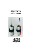
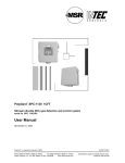
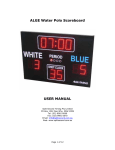
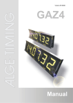
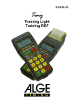
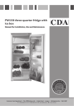
Version-E080421
Manual
TED-TX / RX
Seite 2
1
2
3
4
5
6
7
8
9
10
11
12
13
14
15
antenna
green holder with velcro fastener
light-emitting diode
banana plug yellow, data input
banana plug green, signal input
banana plug black, shared ground (compound)
DIN-plug: data and signal input as well as external feed
3/8 thread measured in inches, for tripod fastening
code-switcher (16 positions)
device-button
device-switcher
code-switcher (10 positions)
fastening screw for battery-cover
battery-cover
type shield with device number
1
2
3
4
5
6
7
8
9
10
11
12
13
14
15
antenna
red holder with velcro fastener
light-emitting diode
banana plug yellow, data output
banana plug green, signal output
banana plug black, shared ground (compound)
DIN-plug: data and signal output as well as external feed
3/8 thread measured in inches, for tripod fastening
code-switcher (16 positions)
device-button
device-switcher
code-switcher (10 positions)
fastening screw for battery cover
battery cover
type shield with device number
TED-TX / RX
Table of content
1
2
2.1
2.2
2.2.1
2.2.2
2.3
2.3.1
2.3.2
2.4
2.4.1
2.4.2
3
3.1
3.2
3.3
3.4
3.5
3.6
4
4.1
4.2
4.3
4.4
4.5
5
5.1
5.1.1
5.1.2
5.2
5.2.1
5.2.2
5.2.3
5.2.4
5.3
6
General ....................................................................................................................................... 4
Power supply ............................................................................................................................. 5
Battery exchange......................................................................................................................... 5
Operation with Alkaline batteries ................................................................................................. 6
Battery warning........................................................................................................................ 6
Operation time ......................................................................................................................... 6
Operation with NiCd-accus.......................................................................................................... 7
Accu warning ........................................................................................................................... 7
Operation time ......................................................................................................................... 7
External supply ............................................................................................................................ 8
Direct supply ............................................................................................................................ 8
Supply by the timing device..................................................................................................... 8
Implementation .......................................................................................................................... 9
Installation.................................................................................................................................... 9
Switch-on ................................................................................................................................... 10
Choice of operation mode ......................................................................................................... 11
Addressing................................................................................................................................. 12
Field strength test for site selection........................................................................................... 13
Annoyance test – tapping of the receiver for disturbing signals................................................ 14
Impulse transmission.............................................................................................................. 15
Impulse transmission of a startgate........................................................................................... 16
Impulse transmission of a photocell .......................................................................................... 16
Impulse transmission RLS with adapter 129-06........................................................................ 17
Impulse transmission with more than 2 timing channels ........................................................... 17
Impulse transmission of more timing channels with Timy and cable 207-10 ............................ 19
Data transmission ................................................................................................................... 20
Data transmission 1 second ...................................................................................................... 21
Data transmission from Timer S4 to Timer S4 ...................................................................... 21
Data transmission from ALGE timing device to printer P4A.................................................. 22
Data transmission 0,1 seconds ................................................................................................. 23
Data transmission to ALGE displayboard.............................................................................. 23
Data transmission from Comet to ALGE soccer displayboard .............................................. 23
Data transmission from a ALGE timing device to Comet Parallel display............................. 24
Data transmission from ALGE timing device to PC............................................................... 24
Data transmission directly ......................................................................................................... 24
Technical data.......................................................................................................................... 25
Subject to technical alterations in terms of improvement!
Download the latest manual for free on our homepage http://www.alge-timing.com/.
TED manual copyright by: ALGE-TIMING
Rotkreuzstraße 39
A-6890 Lustenau
Seite 3
TED-TX / RX
1 General
Purpose:
Wireless transfer of timing impulses or data
Transfer frequency :
in 70cm band
TED-TX10:
Teledata transmitter with an output performance of 10mW
appr. 1,5 km range, l/4 antenna
TED-RX10:
Teledata receiver to TED-TX10 with l/4 antenna
TED-TX400:
Teledata transmitter with an output performance of 400mW
appr. 5 km range, BNC antenna
TED-RX400:
Teledata receiver to TED-TX400 with BNC antenna
Minimal equipment components: 1x TED-TX and 1x TED-RX
Expanded Accessories:
added TED-TX for impulse and data transfer, added TED-RX
for data transfer
RX-C10 for impulse transfer if you use more than two timing
channels
Cognition feature for TED-TX:
type shield (15) and green holder (2)
Cognition feature for TED-RX:
type shield (15) and red holder (2)
Indication on type shield:
device type
device number
Impulse transfer:
The impulse transfer works directly from a ALGE-emitter to the
ALGE timing device.
Data transfer ALGE "1 Sec.":
Every data set will be transfered 10 times out of
safety reasons. Onedata set per second will be
transfered.
Data transfer ALGE "0,1 Sec":
Every data set will be transfered once. One data
set per 0,1 seconds will be transfered.
Data transfer 2400 Baud:
Every data set will be transfered once with 2400
Baud. At the beginning as well as at the end of
each data set you have to indicate an identifier in
order to start and to stop the data transfer.
Data transfer 4800 Baud:
Every data set will be transfered once with 4800
Baud. At the beginning as well as at the end of
each data set you have to indicate an identifier in
order to start and to stop the data transfer.
Data transfer directly:
All data will be transfered, the transmitter (TEDTX) is always on.
Seite 4
TED-TX / RX
System test:
Field strength test
Annoyance test
Power supply:
with 6 batteries or with 6 NiCd-accus or with
external supply
Radio permission:
The permission regulations in Europe variies from country to country.
For some countries you have to apply for a permission for our TED-TX400.
If you need any information concerning this matter , please get in contact with your ALGE
representative.
2 Power supply
There are two types of power supply:
Internal power supply with six batteries (Mignon) or accus (Typ AA)
External power supply with ALGE power supply unit, via timing device or a 12V
battery.
2.1
Battery exchange
You can reach the battery cover at the lower side of
the TED´s.
The knurled screw must be unscrewed anticlockwise.
Remove the cover.
Remove the batteries (put up the device in order that the
batteries will slip out.)
Set in the new (or loaded) battery.
(Notice the polarity, see battery cover)
Put on the cover and screw the knurled screw.
The screw must be screwed to the stop position.
Seite 5
TED-TX / RX
2.2
Operation with Alkaline batteries
Every TED requires 6 Alkaline batteries (Type AA). The battery status will be shown during
the normal operation with help of the diodes.
Color of diode (3)
green
border between green and orange
orange
border between orange and red
red
out
Battery capacity
35-100 %
ca. 35 %
20 to 35 %
ca. 20 %
less than 20 %
empty
The TED switches-off automatically, if the battery tension is below 5 Volt!
ATTENTION: The light-emitting diode has an other function during the field strength test!
(see point 3.5)
2.2.1 Battery warning
If the battery has less than 20% capacity (LED red) then the TED-TX will transfer this
information the the TED-RX together with the next data set or information. He will switch-on
the internal loudspeaker, after that you can hear alternately a high-pitched and a low tone.
The TED-RX will always activiate the internal loudspeaker as soon as the battery capacity is
below 20%.
2.2.2 Operation time
The above indicated measurings refer to Alkaline batteries (Type Energizer) at room
temperatures (25°C).
Please pay attention to the fact, that the battery capacity will be extremely reduced at low
temperatures. (at –20°C approx. just 20% capacity).
TED-TX10
TED-TX10
TED-TX10
TED-TX10
TED-TX400
TED-TX400
TED-TX400
TED-TX400
TED-RX
Seite 6
without photocell
with photocell
----without photocell
with potocell
-------
1 impulse per minute
1 impulse per minute
1 data set per minute
always sends data
1 impulse per minute
1 impulse per minute
1 data set per minute
always sends data
the same in all
operation modes
approx. 300 hours
approx. 66 hours
approx. 270 hours
approx. 54 hours
approx. 270 hours
approx. 60 hours
approx. 54 hours
approx. 6 hours
approx. 54 hours
TED-TX / RX
2.3
Operation with NiCd-accus
Every TED requires 6 NiCd-accus (Typ AA).The accus cannot be loaded in the device. In
order to load you will need a separately loading station. The accu sitution (accu capacity) will
be shown during the normal operation with help of the light-emitting diodes (3).
Color of diode (3)
green
border between green and orange
orange
border between orange and red
red
out
Battery capacity
15 to 100 %
approx. 15 %
5 to 15 %
approx. 5 %
less than 5 %
empty
The TED switches automatically off, if the battery pressure goes below 5 Volt!
Attention: The light-emitting diode has an other function during the field strength test! (see
point 3.5)
2.3.1 Accu warning
The same as Alkaline batteries.
2.3.2 Operation time
The above indicated measurings refer to accus of the type Panasonic 700mAh at room
temperatures (25°C).
Please pay attention to the fact, that the battery capacity will be reduced at low temperatures.
(at –20°C approx. just 80% capacity).
TED-TX10
TED-TX10
TED-TX10
TED-TX10
TED-TX400
TED-TX400
TED-TX400
TED-TX400
TED-RX
without photocell
with photocell
----without photocell
with photocell
-------
1 impulse per minute
1 impulse per minute
1 data set per minute
always sends data
1 impulse per minute
1 impulse per minute
1 data set per minute
always sends data
the same in all operation
modes
approx. 100 hours
approx. 22 hours
approx. 90 hours
approx. 18 hours
approx. 90 hours
approx. 20 hours
approx. 18 hours
approx. 2 hours
approx. 18 hours
Seite 7
TED-TX / RX
2.4
External supply
The TED can be supplied by a power supply unit.
Supply pressure:
TED-TX10
TED-TX400
TED-RX
+6,5 to 28 VDC
+9 to 15 VDC
+6,5 to 28 VDC
2.4.1 Direct supply
The TED can be supplied directly by the following ALGE
power supply units:
NLG4
NLG8
LG-Comet (not for TED-TX400)
NBG
NG13
PS12
2.4.2 Supply by the timing device
In the operation type impulse transfer, the TED-RX can be supplied by the power supply unit
ot the timing device. Therefore you need cable 004-05 between the TED-RX and the timing
device.
ATTENTION: The supply just functions, if the timing device is connected to an external
supply.
LG-Comet cannot supply Comet and the TED at the same time.
Seite 8
TED-TX / RX
3 Implementation
The reach of the radio contact is strongly depending on the location of the transmitter and
receiver. In many cases you can improve the received field strength (high field strength =
high safety) by a minimal relocation if the TED-TX or RX.
3.1
Installation
There are different possibilities to mount the TED:
Bad:
The TED should never
stand on the ground.
Too much reach will be
lost.
Good:
Mounting with Velcro
fastener. In critical
situations, always make
an over-head-mounting.
Bad:
The antenna must
always be uprightly.
Good:
Mounting on a tripod
(3/8 inch)
Bad:
There mustn’t be any
parts near the antenna!
Seite 9
TED-TX / RX
Used for small and middle distances.
3.2
Switch-on
Normal operation
-
Switch-on with device-switcher (11)
TED works in operation mode „Impulse transfer“
Light-emitting diode blinks
Test-Mode
-
Push device-switcher (10)
Device-switcher (11) to „ON“, light-emitting diode should blink
Let loose of the device-switcher.
Test-Mode will automatically switch-off after one minute,
manually with device-switcher (10)
Data transfer ALGE 1 Sec.
Switch-on theTED, light-emitting diode must blink
If the first data set is transfered in the right format, then the data
transfer will be activated for 1 second.
Data transfer ALGE 0,1 Sec.
Set code-switcher (12) of TED-TX and RX to position 1
Switch-on the TED, light-emitting diode must blink
Data transfer 2400 Baud
-
Seite 10
Set code-switcher of TED-TX and RX to position 3.
Switch-on the TED, light-emitting diode must blink
Every data set will be transfered once with 2400 Baud.
At the beginning as well as at the end of each data set you
have to indicate an identifier in order to start and to stop the
data transfer.
TED-TX / RX
Data transfer 4800 Baud
-
Data transfer directly
-
-
3.3
Set code-switcher of TED-TX and RX to position 4.
Switch-on the TED, light-emitting diode must blink
Every data set will be transfered once with 4800 Baud.
At the beginning as well as at the end of each data set you
have to indicate an identifier in order to start and to stop the
data transfer.
Set code-switcher of TED-TX and RX to position 6.
Light-emitting diode of TED-RX must shine.
Light-emitting diode of TED-TX blinks. At first you
have to send a data set that the TED-TX switch
in the direct mode (illuminating diode goes
from blinking to shine).
Every data set will be transfered.
Choice of operation mode
Switcher
Code-switcher
(12)
Code-switcher (9)
Device-pushbutton (10)
Signal mode
Data mode
Position 0: data transfer ALGE 1 second
Position 1: data transfer ALGE 0,1 second
Position 2: without function
Position 0 to 9
Position 3: data transfer 2400 Baud
for choice of timingPosition 4: data transfer 4800 Baud
channel
Position 6: data transfer directly
Position 7 to 9: without function
for addressing
for addressing
field strength tst On/Off
repeat last data set
The field strength test can also be started by triple short-circuiting of the green and black
banana plug.
Seite 11
TED-TX / RX
3.4
Addressing
The code-switcher (9) for addressing has got 16 positions
and is accessible from the bottom. All TED-TX and RX must be
installed to the same address if they work in one system.
Chose the requested address with the
provided screw driver. The arrow of the
switcher shows the position. Our factory
settins is at position 0.
If several TED’s are used in the same
area, you have to work with different
addresses. So you are safe of false
impulses or data, though not against
blocking of another device.
Code-switcher (9)
Position = 0
Position = 1
Position = 2
Position = 3
Position = 4
Position = 5
Position = 6
Position = 7
Position = 8
Position = 9
Position = A
Position = B
Position = C
Position = D
Position = E
Position = F
Address
Address = 0
Address = 1
Address = 2
Address = 3
Address = 4
Address = 5
Address = 6
Address = 7
Address = 8
Address = 9
Address = A
Address = B
Address = C
Address = D
Address = E
Address = F
If you will avoid any blocking of another TED, so you have to change to another radiofrequency.
Example impulse-transfer of start signal
TED –TX and RX must be adjusted to the same address.
Seite 12
TED-TX / RX
3.5
Field strength test for site selection
The field strength test can just be carried out in the operation mode „impulse transfer“.
If you would like to work smooth with your TED, you have to choose an appropriate location.
Activate field strength:
-
Switch-on TED-TX
Push device-button (10)
Mount the TED aloft.(side 9)
Switch-on TED-RX
-
The loudspeaker of the TED-RX makes a tone and the lightemitting diode blinks.
The higher the tone, the better the field strength.
-
Diode blinks green >
Diode blinks orange >
Diode blinks red
>
Signal is good
Signal is low
Signal missing or too low
-
If the loudspeaker plays back voices, it means that this radio
frequency is used for voice radio. This can cause data or
impulse losses.
-
The field strength test will automatically be finished after 1
minute by the TED-TX.
For the retrieval of the ideal location you have to move the TED-RX. The best location is
chosen if the tone is as high as possible and if the diode is blinking green.
The field strength can only be evaluated with TED-RX!
TED-TX and RX must have a distance of 5 to 10 meters between them to assure a troublefree work.
Seite 13
TED-TX / RX
3.6
Annoyance test – tapping of the receiver for
disturbing signals
If you push the device-button of the TED-RX for about half a second, the loudspeaker will be
activated and you can intercept the channel for possible disturbing signals.
At the same time the light-emitting diode shows the field strength of the received signals,
also those of a possible disquieter
ATTENTION:
The electric power consumption of the TED-RX doubles during this test.
Push the device-button to switch-off the loudspeaker.
Seite 14
TED-TX / RX
4 Impulse transmission
The impulse transmission functions directly from an ALGE emitter to a ALGE timing device
via radio.
Every impulse, transfered by the TED, has a constantly delay of 0,100 seconds.
Maximum fault ; 0,001 seconds.
If only the start impulse is transfered by TED, you have to add a tenth second to the
run time.
If only the finish impulse is transfered by TED, you have to discount a tenth second of
the run time.
If the start impulse as well as the finish impulse is transfered by TED, the run time is
accurately.
TED-TX is from the beginning of the first impulse blocked for 0,163 seconds respectively
incidental impulses within this time will be delayed until this time is expired.
TED-RX is from the beginning of the first impulse blocked for 0,1 seconds and ignores all
impulses within this period.
C
A
Bounce protection
B
+5V
Inside the TED-TX is a built-in bounce
protection integrated. This bounce protection
prevents double-impulses. (50 ms)
0V
A
B
C
D
E
Bounce at the beginning of an impulse
Bounce at the end of an impulse
Impulse duration plus bounce duration
Bounce protection time 50 ms
Bounce protection abrupted,
since 50 ms were not expired
D
E
E
Control of the impulse transmission
If a timing impulse is transfered, the diode of TED-TX and RX will blink once again.
Safety of the impulse transmission
Please bare in mind that the radio connection may be disturbed by outside influences. That
means that in case of annoyances, there can’t be any transmissions of impulses.
!! With an impulse transmission via radio we can never assure the same security as by an
impulse transmission by cable. !!
The following ALGE-devices can be used as emitter:
all startgates
photocells RLS, RLS3
SM8, STB1, Tapeswitch, hand taste 023-xx
Touchpads TP
ASC
Seite 15
TED-TX / RX
The following ALGE timing devices can be used as impulse receiver:
TDC4000
TDC8000
TDC8001
Timy
Comet
Timer S4
Timer S3
Videotimer VT2 / VT2D
OPTIc (only start impulse)
With the standard TED, two timing channels can be transmitted. Normally – if cable 004-xx is
used – it will be start channel C0 and finish channel C1.
4.1
Impulse transmission of a startgate
4.2
Impulse transmission of a photocell
Seite 16
TED-TX / RX
4.3
Impulse transmission RLS with adapter 129-06
You can adjust with adapter 129-06 if you will receive a start or stop impulse.
This has the advantage if you have e.g. a round course, you just need one photocell.
4.4
Impulse transmission with more than 2 timing
channels
Here you need adapter RX-C10 so that you can transfer up to 10 timing channels in
connection with TDC8000/8001 and Timer S4. Therefore you need several TED-TX. You can
transfer 2 timing channels per TED-TX.
You can adjust the timing channels at the TED-TX with the code-switcher (12).
The code-switcher (12) don’t have any function in this operation.
ATTENTION: Blocking time (see point 4, impulse transmission)
With the small provided screw driver you can adjust the
arrow of the code-switcher to the right position.
TED-TX
Code-Schalter (12)
switch position =
switch position =
switch position =
switch position =
switch position =
switch position =
switch position =
switch position =
switch position =
switch position =
0
1
2
3
4
5
6
7
8
9
TED-TX timing channel
banana socket
green (5) and black (6)
0
1
2
3
4
5
6
7
8
0
TED-TX DIN-socket
timing channel
on pin 1
0
1
2
3
4
5
6
7
8
0
TED-TX DIN-Stecker
timing channel
on pin 2
1
2
3
4
5
6
7
8
9
2
Seite 17
TED-TX / RX
Timing with 10 timing channnels at a Ski test run:
Adjustment of the code-switcher (12) to the TED-TX
Channel
Function
Emitter
C0
C2
C3
C4
C5
C6
C7
C8
C9
C1
Start
Intermediate time 1
Intermediate time 2
Intermediate time 3
Intermediate time 4
Intermediate time 5
Intermediate time 6
Intermediate time 7
Intermediate time 8
Finish
Startgate
Photocell
Photocell
Photocell
Photocell
Photocell
Photocell
Photocell
Photocell
Photocell
Seite 18
Switcher
position (12)
0
1
2
3
4
5
6
7
8
0
Cable type
000-10
001-10
001-10
001-10
001-10
001-10
001-10
001-10
001-10
001-10
Connection plug
at TED-TX
Banana plug 5+6
DIN-plug (7)
DIN-plug (7)
DIN-plug (7)
DIN-plug (7)
DIN-plug (7)
DIN-plug (7)
DIN-plug (7)
DIN-plug (7)
DIN-plug (7)
TED-TX / RX
4.5
Impulse transmission of more timing channels with
Timy and cable 207-10
The cable 207-10 works only with the Timy. You can only use start cables (000-xx or
002-xx) for this system. There will be no impulse and also the Timy prints an error message
when you use a stop cable.
These are the functions of the code switch (12). This have no use in the program Training
REF, here it is only necessary that the TED channels are different.
Codeswitch Chanal Function
0
C0
Start
1
C1
Finish
2
C2
Intermediate
3
C3
Intermediate
4
C4
Intermediate
5
C5
Intermediate
6
C6
Intermediate
7
C7
Intermediate
8
C8
Intermediate
9
C0
Start
Seite 19
TED-TX / RX
5 Data transmission
Operational area:
Data transmission from an ALGE timing device to a ALGE displayboard
Data transmission from Timer S4 to Timer S4 (program 0)
Data transmission from ALGE timing device to printer P4A
Data transmission from ALGE timing device to Comet parallel display
Data transmission from Comet to football-displayboard
Data transmission from ALGE-timing device to a PC
Data transmission from PC to PC
There exists different types of operating modes for data transmission:
Data transmission ALGE 1 second
Data transmission ALGE 0,1 second
Data transmission 2400 Baud
Data transmission 4800 Baud
Data transmission directly
ALGE Protocol, 1 data set per second
ALGE Protocol, 1 data set per tenth
second
Data transmission with control character
and 2400 Baud
Data transmission with control character
and 4800 Baud
Data transmission without protocol of
2400 to 4800 Baud
Data repetation
If the data don’t arrive at the receiver, you can trigger off a data repetation at the transmitter.
The last data set is always stored in the TED-TX.
by pushing the device-button (10) at TED-TX
or
by pushing of the hand taste, connected on the green and
black banana plugs of the TED-TX
Seite 20
TED-TX / RX
5.1
Data transmission 1 second
Adjustment:
Code-switcher (12) of TED-TX and RX at position 0
If the TED-TX recognizes reasonable data (ALGE protocol), he will change to the operating
mode “data transmission 1 second”. In this mode, every data set will be transfered 10 times
together with a checksum.
As soon as the TED-RX has received a data set with right checksum, he will display the data
set.
This operating mode is used if it is important, that the receiver will get all data in a secure
way. But this just functions if the data will not be sent all the time. If data are sent all the time
(e.g. for a displayboard), it may happen that parts of the data will get lost.
5.1.1 Data transmission from Timer S4 to Timer S4
The Timer S4 can supply the TED-TX via a serial interface.
Timer S4 with TED without supply of the TED’s.
Seite 21
TED-TX / RX
Data transmission of the start time from a synchronous Timer S4 to another Timer S4
- Adjust Timer S4 at the start to program 3 and indicate daytime
Push yellow and red button at the same time.
The diplay of the Timer S4 shows „HP 0:00.00“
Type the hours with the red button.
Type the minutes with the yellow button.
- Adjust Timer S4 at the finish to program 0 and indicate daytime
Push yellow and red button at the same time.
Push yellow and red button at the same time once again.
The display of the Timer S4 shows „SY 0:00.00“
Type the hours with the red button.
Type the minutes with the yellow button.
- Start both Timer S4 together (synchronous start) via a start cable (channel C0).
- The display of the Timer at the finish shows the daytime.
- To delete the daytime, push yellow and red button together.
- Program 0 works now as described in the manual for Timer S4.
- The start-Timer must be brought to the start.
Data repetation
If the start time don’t arrive at the finish-Timer, you can send the data once again (see side
18).
5.1.2 Data transmission from ALGE timing device to printer P4A
If the output „RS232“ is used by a timing device, you must use cable 060-10 for the TED-TX.
Seite 22
TED-TX / RX
5.2
Data transmission 0,1 seconds
Adjustment: Code-switcher (12) of TED-TX to RX at position 1
Just for data with ALGE protocol. Every data transmission from TED-TX to RX happens
once. Every data set has got a checksum, if these are right, the received data will be
displayed.
In this operation mode it is possible to transfer a running tenth.
This operation mode is used if it is important, that the transfered data must be available
immediately or if many data sets should be transfered in a short time. The transmission
security isn’t as high as at mode “data transmission 1 second”.
5.2.1 Data transmission to ALGE displayboard
5.2.2 Data transmission from Comet to ALGE soccer displayboard
In order to supply TED-TX from a Comet you need cable 108-10.
We would recommend to supply the Comet by an ALGE power-supply unit.
Seite 23
TED-TX / RX
5.2.3 Data transmission from a ALGE timing device to Comet Parallel
display
5.2.4 Data transmission from ALGE timing device to PC
5.3
Data transmission directly
Adjustment: Code-switcher (12) of TED-TX and RX at position 6
Adapter 119—5 must be connected to the TED-TX
At first you have to send a data set that the TED-TX switch
in the direct mode (illuminating diode goes from blinking to shine).
Every data set with a baudrate of 2400 up to 4800 Baud will be sent. No control-character is
required. The transmitter is always online, that means that a power-supply unit for the
transmitter is recommended by us.
The data won’t be checked by the receiver, but passed on as received. The verification
should be conducted of the Software of the receiving unit. (PC).
Advantage:
Every data set will be transfered. No control-characters are required.
Every optional data protocol will be transfered.
Disadvantage:
The transmitter TED-TX has a high power consumption, since it is
always online. Since the data are sent without protocol, the receiver is
able to check the data.
Range of use:
Wireless data transmission with optional data protocol from one device
to another (PC).
Seite 24
TED-TX / RX
OR
6 Technical data
Operating frequency:
Standard 10mW
Standard 400mW
Optional
band)
Broadcast performance:
TED-TX10
TED-TX400
10mW
400mW
Range:
TED-TX10
TED-TX400
approx. 1,5 km
approx. 5 km
Signal input TED-TX:
activ low, at least 10 ms, debounce-time approx. 50 ms
Signal output TED-RX:
activ low, 100 ms
Supply:
external
TED-TX10 and RX
TED-TX400
internal
6 x Alkaline batteries 1,5 V Typ AA or
6 x NiCd accus 1,2 V Typ AA
Charging rate:
TED-TX10
TED-TX400
TED-RX
Operation time:
433,500MHz
433,800MHz
from 433,050 up to 434,790MHz (in 70cm
+6,5 to 28 VDC
+9 to 15 VDC
Transmitting operation
Standby Mode
Transmitting operation
Standby Mode
Normal operation
Test operation
approx. 35 mA
approx. 3 mA
approx. 300 mA
approx. 3 mA
approx. 35 mA
approx. 70 mA
see side 6 and 7
Seite 25
TED-TX / RX
RS232 interface (true for TED-TX and RX):
Input- Output-format:
Transfer speed:
Connector assignment:
1 Startbit, 8 AXCII Bit, no Parity-Bit, 1 Stopbit
2400 or 4800 Baud
TED-TX DIN-plug:
1
Impuls Input (Start)
2
Impuls Input (Stop)
3
GND
4
Input V-ext.
5
Output +5 V stabilised
Input +5V
6
Data input
Banana plug:
with yellow marking
with green marking
with black marking
Antenna:
Dimensions:
Seite 26
Data, identically with PIN 6 of DIN-plug
Impulse, identically with PIN1 of DIN-plug
GND, identically with PIN 3 of DIN-plug
at TED-TX10 and TED-RX10
at TED-TX400 and TED-RX400
Working temperature:
Weight:
TED-RX DIN-plug:
1
Impule output (Start)
2
Impulse output (Stop)
3
GND
4
Input V-ext.
5
Input +5V
6
Data output
-20 up to +50°C
without batteries
with batteries
approx. 600g
approx. 750g
l/4 antenna, approx. 165mm
BNC connection for 50 W antenna
TED-TX / RX
Seite 27
TED-TX / RX
Note:
Seite 28