1
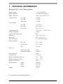
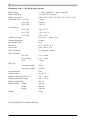
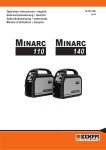
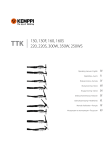
Operation instructions • english
Gebrauchsanweisung • deutsch
Gebruiksaanwijzing • nederlands
Manuel d’utilisation • français
KEMPOMAT
1701, 2100
1921440E
0531
CONTENTS
1.
2.
3.
4.
5.
6.
7.
8.
PREFACE......
3
1.1.
1.2.
1.3.
1.4.
1.5.
1.6.
1.7.
Introduction ......................................................................................................................... 3
Product introduction ............................................................................................................ 3
Main components ................................................................................................................ 3
Switches and controls .......................................................................................................... 4
Mains connection ................................................................................................................ 4
Locating the machine .......................................................................................................... 4
Operation safety .................................................................................................................. 4
2.1.
2.2.
2.3.
2.4.
2.5.
Welding gun main components ........................................................................................... 5
Wire feeding mechanism components................................................................................. 5
Installation of welding gun .................................................................................................. 6
To fit the wire reel ............................................................................................................... 6
To install the welding wire .................................................................................................. 6
3.1.
3.2.
3.3.
3.4.
3.5.
3.6.
3.7.
3.8.
3.9.
3.10.
3.11.
Places of use ........................................................................................................................ 6
Main switch ......................................................................................................................... 7
Polarity for welding ............................................................................................................. 7
Adjustment of arc roughness/Kempomat 2100 ................................................................... 7
Earthing .............................................................................................................................. 7
To select welding mode ....................................................................................................... 7
To select welding parameters .............................................................................................. 8
Thermostat ........................................................................................................................... 8
Shield gas ............................................................................................................................ 8
Welding ............................................................................................................................... 9
Storage .�
9
4.1.
4.2.
Daily maintenance ............................................................................................................... 9
Regular maintenance ........................................................................................................... 9
INSTALLATION OF WELDING GUN AND WIRE .........................................................................5
OPERATING WELDING EQUIPMENT .........................................................................................6
MAINTENANCE OF WELDING UNIT ...........................................................................................9
DISPOSAL OF THE MACHINE ..................................................................................................10
ORDERING NUMBERS ..............................................................................................................10
TECHNICAL INFORMATION ..................................................................................................... 11
TERMS OF GUARANTEE ..........................................................................................................13
2 – KEMPOMAT 1701, KEMPOMAT 2100 / 0531
© KEMPPI OY
1. PREFACE
1.1. Introduction
Congratulations on having purchased this product. Properly installed Kemppi products should
prove to be productive machines requiring maintenance at only regular intervals. This manual is
arranged to give you a good understanding of the equipment and its safe operation. It also contains maintenance information and technical specifications. Read this manual from front to back
before installing, operating or maintaining the equipment for the first time. For further information on Kemppi products please contact us or your nearest Kemppi distributor.
The specifications and designs presented in this manual are subject to change without prior
notice.
In this document, for danger to life or injury the following symbol is used:
Read the warning texts carefully and follow the instructions. Please also study the Operation
safety instructions and respect them when installing, operating and servicing the machine.
1.2. Product introduction
Kempomat is a welding machine with integrated welding current supply and wire feeder. The
power supply converts the mains voltage suitable for welding. The wire feeding mechanism
feeds wire from a roll through the welding gun nozzle into the arc. A weld is made by moving
the welding gun.
1.3. Main components
A
B
C
D
E
F
G
H
I
J
K
Housing
Door plate
Handle
Earth cable socket
Gun connector
Polarity selector
Switches and controls
Wire feed mechanism
Feed roll latch
Roll brake control
Gas bottle holder
A
I
C
G
J
H
E
A
B
K
F
D
This equipment’s electromagnetic compatibility (EMC) is designed for use in an industrial
environment. Class A equipment is not intended for use in residential location where the
electrical power is provided by the public low-voltage supply system.
© KEMPPI OY
KEMPOMAT 1701, KEMPOMAT 2100 / 0531 – 3
1.4. Switches and controls
7
8
9
1
2
3
4
5
2
1
3
6
4
5
6
7
8
9
Main switch and pilot light
Overheat control lamp
Voltage selector
Polarity selector
I Return current dix connector
(coarser arc), only Kempomat 2100
II Return current dix connector
(softer arc)
Welding method selector (2-way/
spot or 4-sequence)
Wire feed rate adjustment
potentiometer
Timer potentiometer
1.5. Mains connection
The machine is supplied with the mains cable installed. The cable may be disconnected and the plug
installed only by an authorised electrician! See under “Maintenance”. The fuse rating and the cable
diameter are given in the chapter Technical data in the end of this document.
1.6. Locating the machine
Use the front panel handles to move the machine. Use ropes for lifting. Do not use a hook or a chain!
Place the machine on a horizontal, stable and clean base. Protect from hard rain and intensive sunshine. Ensure unhindered circulation of cooling air.
1.7. Operation safety
Please study these Operation safety instructions and respect them when installing, operating and
servicing the machine.
Welding arc and spatters
Welding arc hurts unprotected eyes. Be careful also with reflecting arc flash. Welding arc and spatter
burn unprotected skin. Use safety gloves and protective clothing.
Danger for fire or explosion
Pay attention to fire safety regulations. Remove flammable or explosive materials from welding place.
Always reserve sufficient fire-fighting equipment on welding place. Be prepared for hazards in special
welding jobs, eg. for the danger of fire or explosion when welding container type work pieces. Note!
Fire can break out from sparks even several hours after the welding work has been finished!
Mains voltage
Never take welding machine inside a work piece (eg. container or truck). Do not place welding
machine on a wet surface. Always check cables before operating the machine. Change defect cables
without delay. Defect cables may cause an injury or set out a fire. Connection cable must not be
compressed, it must not touch sharp edges or hot work pieces.
Welding power circuit
Isolate yourself by using proper protective clothing, do not wear wet clothing. Never work on a wet
surface or use defect cables. Do not put MIG-gun or welding cables on welding machine or on other
electric equipment. Do not press MIG-gun switch, if the gun is not directed towards a work piece.
Welding fumes
Take care that there is sufficient ventilation during welding. Take special safety precautions when
welding metals which contain lead, cadmium, zinc, mercury or beryllium.
4 – KEMPOMAT 1701, KEMPOMAT 2100 / 0531
© KEMPPI OY
2. INSTALLATION OF WELDING GUN AND WIRE
Select the flow nozzle, the wire conduit and the feed roll to match the wire. The machine is
supplied with 0.6 and 0.8 mm dia. wires.
2.1. Welding gun main components
4
3
2
6
5
1
1
2
3
4
5
6
Handle
Trigger
Neck
Gas nozzle
Gun connector
Wire conduit
2.2. Wire feeding mechanism components
© KEMPPI OY
KEMPOMAT 1701, KEMPOMAT 2100 / 0531 – 5
2.3. Installation of welding gun
To ensure trouble-free welding use only original Kemppi welding guns. Do not use a damaged
gun.
Make sure the gun wire conduit and the flow nozzle match the manufacturer’s recommendations
for the type and diameter of the wire you use. Too small a conduit may overload the wire feed
device and disturb wire feeding.
Tighten the gun quick connector to eliminate voltage losses. A loose joint will make the gun
and the wire feeder warm. After this check that the conduit inside the wire liner does not touch
the feed rolls.
2.4. To fit the wire reel
1.
2.
3.
4.
Release the reel latch claws by turning
them 1/4 of a turn.
Insert the reel so that the hole in the reel
will be at the pin of the device. Use reel
supports, when required.
Insert the reel. N.B.!The wire travels from
the top of the roll to the wire feed unit.
Secure the reel by turning the latch.
2.5. To install the welding wire
Before installing the welding wire check that the feed roll, the wire conduit and the flow nozzle
match the wire.
1.
Fit in the feed roll and check once more that the correct groove is in line with the wire.
2.
Round the end of the wire and push it through wire guide into burner’s wire tube
3.
Check, that the wire is in the groove and set clamping lever on its place. Tighten only a
little.
4.
Feed the wire into the gun by pressing the gun switch. Wire clamping force to the feed
roll is correct, when wire coming out of flow nozzle can be lightly slowed down with
fingers.
5.
Regulate braking power of wire roll by turning the adjustment screw in the centre of
latch with a screw driver. Do not tighten too much, as the brake puts an additional load
on motor.
Note! Not wire nor wire reel must touch the
unit body, as it creates a danger of short circuit!
When using aluminium wire it might be advisable
to totally remove the spiral part of the back guide. If
you use cored wire, check the wire manufacturer’s
instructions on use and safety first.
3. OPERATING WELDING EQUIPMENT
Also see section 1. Before you start using the welding machine.
Welding in fire or explosion hazard sites is absolutely forbidden!
Note! When welding in other than industrial surroundings, the unit might cause disturbance
in radio equipment. Taking necessary precautions is the responsibility of the user.
3.1. Places of use
Kempomat is a basic welding machine for MIG/MAG welding in maintenance, servicing and
repair works. It is suitable for both normal MIG/MAG welding as well as for welding without
shield gas.
6 – KEMPOMAT 1701, KEMPOMAT 2100 / 0531
© KEMPPI OY
3.2. Main switch
In position I control circuit of the unit is live and indicator light of main switch is on. Power
source and welding circuit become active, when gun trigger is pressed.
Note. If mains power is shut off or triggered, you must wait 10 to 15 sec, before switching
power back on.
Always switch the unit on and off from the main switch. Do not use the mains plug as a
switch!
Beware that neither you yourself, gas bottles nor electric equipment become a
part of the welding electric circuit!
3.3. To select polarity for welding
Solid wire is usually welded in + pole and cored wire in - pole gun. Check for the recommended polarity on package or product seller. When welding very thin plates (0.5 to 0.7 mm)
- polarity might also work best for solid wire.
3.4. Adjustment for arc roughness I
II
/Kempomat 2100
Arc roughness is set by connecting the return current cable or polarity selector cable to the one
of the two dix connectors on the front plate.
The connector marked with symbol I gives a rougher arc, which is used for welding of thin
sheets and ferrous metals by lower currents. Consider especially with CO2 shielding gas.
The connector marked with symbol II is suitable for greater currents and especially for aluminium and stainless materials. The most suitable roughness is, however, most dependent on the
welding case. You will find the best position by testing.
3.5. Earthing
If possible, always fix the earth clamp of return current cable directly on the welding target.
Clean earth clamp touch surface of paint and rust. Secure clamp so, that the surface it is touching is as large as possible. Finally check that clamp sits tightly.
3.6. To select welding mode
Also see section 1.4. Switches and controls.
Use the welding mode selecting switch to select how to regulate shield gas flow and wire feed
in welding gun switch. You have three welding modes to select from:
2T –sequence procedure
Gas flow and wire inch start when gun switch is pressed and end when the switch is released.
Wire feed is in cycles, if timer potentiometer is set on time scale range.
4 T -sequence procedure
Gas flow starts when gun switch is pressed all the way.
When the switch is released, wire inch starts and welding
begins. When the gun switch is pressed again, wire inch is
interrupted and when the switch is released, shield gas flow
ends. Wire inch will be in cycles, if timer potentiometer is set on time scale range.
Spot welding procedure
Shield gas flow and wire inch start, when gun switch is pressed all the way and end when time
set by the timer potentiometer ends or when the gun switch is released. If the timer potentiometer
is in 0 range this procedure will not start.
TIMER potentiometer
Welding can be spaced by selecting a time for welding period on timer potentiometer. Wire feed
and gas flow will be automatically interrupted after set time and automatically restarted.
© KEMPPI OY
KEMPOMAT 1701, KEMPOMAT 2100 / 0531 – 7
3.7. To select welding parameters
1.
2.
Select adjustment step of voltage switch.
Set adjustment potentiometer of wire inch speed on the same number.
3.
4.
Test the weld and make necessary adjustments in wire inch.
If fusion power is not suitable for the target, set the voltage anew. Also adjust wire feed,
if necessary. Repeat until the values suit the target.
Kempomat 1700
Voltage step Open circuit voltage
1
16,1 V
2
17,5 V
3
19,2 V
4
21,1 V
5
23,6 V
6
26,4 V
7
30,1 V
8
34,7 V
Kempomat 2100
Voltage step Open circuit voltage
1
16,9 V
2
18,2 V
3
19,6 V
4
21,1 V
5
22,8 V
6
24,6 V
7
26,4 V
8
28,5 V
9
30,8 V
10
33,1 V
3.8. Thermostat
Thermal protection of the unit prevents the power source from overheating. Thus the unit will not be damaged, even if load during welding exceeds load factor. When overheating pilot lamp lights, welding is
not possible. There is an appr. 3 min delay before the light goes out, and
welding can be normally continued by starting from the trigger. The light
can also signify low supply voltage or an overtly long welding period.
3.9. Shield gas
Handle gas bottle with care, it might explode if it falls down!
Because the danger of falling, the gas bottle must not be higher than 1600 mm.
Shield gas shields the arc and in MAG welding it is also used for reinforcing the weld seam.
Shield gas for steel wire is carbon dioxide (CO2) or mixed gas, where main component is argon
(Ar) and the rest is carbon dioxide. When welding aluminium wire, pure argon is used as shield
gas.
Flow meter must be suitable for gas type. Usually suitable flow is 8 to 10 l/min. If flow is too
slow or too big, the weld seam becomes porous.
Your dealer will give you advice on choosing gas and equipment.
Note! Always mount the gas bottle in upright position in a specially made rack
on the wall or in a bottle trolley. Always close the bottle valve after finishing
welding.
8 – KEMPOMAT 1701, KEMPOMAT 2100 / 0531
© KEMPPI OY
3.10. Welding
Never look at the flame arc without a face shield for arc welding! Protect yourself
and your surroundings from the flame arc and hot spatter!
You can start welding, when selections and adjustments demanded by the work have been done.
Welding begins when wire is pressed to the work piece by pressing the gun switch. Arc forms,
shield gas starts to flow and wire feed inches welding wire out of the gun nozzle.
Note! It is advisable to test welding first on something else than the work piece.
Welding fumes are a possible health hazard, make certain there is sufficient
ventilation during welding!
3.11. Storage
Store the unit in a clean and dry place. Shield it from rain and at temperatures exceeding 25 °C
from direct exposure to sun. There must be sufficient free space in front and back of the unit for
air circulation.
4. MAINTENANCE OF WELDING UNIT
4.1. Daily maintenance
Be careful of mains voltage when handling electric cables!
Clean wire passage in gun and check contact tip regularly.
Always check condition of mains and welding cables before use, change damaged ones.
Note! Mains cable can be changed only by a qualified electrician!
Mains cable is changed as follows:
Kempomat 1701
1.
2.
3.
Detach back plate of wire reel.
Connect mains cable to main switch pins with flat clamps.
Connect green and yellow earth to the body plug marked as earth.
Kempomat 2100
By delivery from the factory the Kempomat machine has
been connected for mains voltage3~400V.
In order to change the mains voltage loosen the right side
plate of the machine, change the connections according to the
enclosed diagram.
4.2. Regular maintenance
KEMPPI service workshops make service contracts with customers about regular maintenance. All parts are cleaned, checked, and if necessary, repaired. Also the operation of welding
machine is tested.
© KEMPPI OY
KEMPOMAT 1701, KEMPOMAT 2100 / 0531 – 9
5. DISPOSAL OF THE MACHINE
Do not dispose of electrical equipment together with normal waste!
In observance of European Directive 2002/96/EC on Waste Electrical and Electronic Equipment
and its implementation in accordance with national law, electrical equipment that has reached
the end of its life must be collected separately and returned to an environmentally compatible
recycling facility. As the owner of the equipment, you should get information on approved
collection systems from our local representative.
By applying this European Directive you will improve the environment and human health!
6. ORDERING NUMBERS
Part
Ordering number
Kempomat 1701 1~ 230 V welding machine
6214171
Kempomat 2100 3~ 230/400 V welding machine
621421001
Earth cable
16mm2, 3 m
4260000
MIG welding gun, 3 m
KMG 20
6251113
MIG welding gun, 3 m
MT 18
6251013
Hub for wire reel
10 – KEMPOMAT 1701, KEMPOMAT 2100 / 0531
4289880
© KEMPPI OY
7. TECHNICAL INFORMATION
Kempomat 1701 1~ 230 V Welding machine
Rated voltage
Mains cable/fuse
Mains connection
Connected load
15 % ED
60 % ED
100 % ED
1~ 230 V 50/60 Hz
3x1,5 mm2/16 A delayed
220 V -10 %...240 V+ 6%
6.5 kVA
3.0 kVA
2.3 kVA
Load capacity
15 % ED
60 % ED
100 % ED
Adjustment range
Voltage adjustment
open circuit voltage, max.
Efficiency
Power ratio
Wire feed speed
Wires with filler
Ø Fe, SS
Ø Cored wire
Ø Al
Wire reel:
maximum weight
maximum diameter
Gun connection
Thermal class
Range of temperature for use
Storage temperature range
Degree of protection
Measurements:
length
width
height
Weight
170 A/21 V
85 A / 18.5 V
76 A / 17.5 V
30 A / 14 V ... 170 A / 22.5 V
8 steps
40 V
70 % / 170 A / 21 V
0,85 / 170 A / 21 V
0 – 16 m/min, stepless
0.6 - 1.0 mm
0.9 - 1.2 mm
1.0 mm
20 kg
300 mm
Euro
H (180 ºC)
-20 … +40 ºC
-40 … +60 ºC
IP 23 C
850 mm
392 mm
750 mm
47 kg
The unit fulfils the CE marking demands.
© KEMPPI OY
KEMPOMAT 1701, KEMPOMAT 2100 / 0531 – 11
Kempomat 2100 3~ 230/400 Welding machine
Rated voltage
Mains cable/fuse
Mains connection
Connected load 25 % ED
60 % ED
100 % ED
Load capacity
25 % ED
60 % ED
100 % ED
Adjustment range
Voltage adjustment
Idle voltage, max.
Efficiency
Power ratio
Wire feed speed
Wires with filler
Ø Fe, SS
Ø Cored wire
Ø Al
Wire reel:
maximum weight
maximum diameter
Gun connection
Thermal class
Range of temperature for use
Storage temperature range
Degree of protection
Measurements: length
width
height
Weight
3~ 230 V 50/60 Hz / 3~ 400 V 50/60 Hz
3x1,5 mm2/10 A delayed
220 V -10 %...240 V+6% / 380 V -10 %...415 V +6 %
7.5 kVA
4.0 kVA
2.8 kVA
200 A / 23 V
130 A / 20.5 V
100 A / 19 V
30 A / 14 V ... 200 A / 24 V
10 steps
40 V
85 % / 200 A / 24 V
0,90 / 200 A / 24 V
0 – 18 m/min, stepless
0.6 - 1.0 mm
0.9 - 1.2 mm
1.0 mm
20 kg
300 mm
Euro
H (180 ºC)
-20 … +40 ºC
-40 … +60 ºC
IP 23 C
910 mm
410 mm
820 mm
54 kg
The unit fulfils the CE marking demands.
12 – KEMPOMAT 1701, KEMPOMAT 2100 / 0531
© KEMPPI OY
8. TERMS OF GUARANTEE
Kemppi Oy provides a guarantee for products manufactured and sold by them if defects in manufacture
and materials occur. Guarantee repairs must be carried out only by an Authorised Kemppi Service Agent.
Packing, freight and insurance costs to be paid by orderer. The guarantee is effected on the date of purchase.
Verbal promises which do not comply with the terms of guarantee are not binding on guarantor.
Limitations on guarantee
The following conditions are not covered under the terms of guarantee: defects due to natural wear and
tear, non-compliance with operating and maintenance instructions, connection to incorrect or faulty supply
voltage (including voltage surges outside equipment spec.), incorrect gas pressure, overloading, transport
or storage damage, fire of damage due to natural causes i.e. lightning or flooding.
This guarantee does not cover direct or indirect travelling costs, daily allowances or accommodation.
Note: Under the terms of guarantee, welding torches and their consumables, feeder drive rolls and feeder
guide tubes are not covered. Direct or indirect damage due to a defective product is not covered under the
guarantee. The guarantee is void if changes are made to the product without approval of the manufacturer,
or if repairs are carried out using non-approved spare parts.
The guarantee is also void if repairs are carried out by non-authorised agents.
Undertaking guarantee repairs
Guarantee defects must be informed to Kemppi or authorised Kemppi Service Agents within the guarantee
period. Before any guarantee work is undertaken, the customer must provide proof of guarantee or proof
of purchase, and serial number of the equipment in order to validate the guarantee. The parts replaced
under the terns of guarantee remain the property of Kemppi.
Following the guarantee repair, the guarantee of the machine or equipment, repaired or replaced, will be
continued to the end of the original guarantee period.
© KEMPPI OY
KEMPOMAT 1701, KEMPOMAT 2100 / 0531 – 13
KEMPPI OY
PL 13
FIN – 15801 LAHTI
FINLAND
Tel (03) 899 11
Telefax (03) 899 428
www.kemppi.com
KEMPPIKONEET OY
PL 13
FIN – 15801 LAHTI
FINLAND
Tel (03) 899 11
Telefax (03) 7348 398
e-mail: [email protected]
KEMPPI SVERIGE AB
Box 717
S – 194 27 UPPLANDS VÄSBY
SVERIGE
Tel (08) 59 078 300
Telefax (08) 59 082 394
e-mail: [email protected]
KEMPPI NORGE A/S
Postboks 2151, Postterminalen
N – 3103 TØNSBERG
NORGE
Tel 33 34 60 00
Telefax 33 34 60 10
e-mail: [email protected]
KEMPPI DANMARK A/S
Literbuen 11
DK – 2740 SKOVLUNDE
DANMARK
Tel 44 941 677
Telefax 44 941 536
e-mail:[email protected]
KEMPPI BENELUX B.V.
Postbus 5603
NL – 4801 EA BREDA
NEDERLAND
Tel (076) 5717 750
Telefax (076) 5716 345
e-mail: [email protected]
KEMPPI (UK) Ltd
Martti Kemppi Building
Fraser Road
Priory Business Park
BEDFORD, MK443WH
ENGLAND
Tel 0845 6444201
Fax 0845 6444202
e-mail: [email protected]
KEMPPI FRANCE S.A.
S.A. au capital de 5 000 000 F.
65 Avenue de la Couronne des Prés
78681 EPONE CEDEX
FRANCE
Tel (01) 30 90 04 40
Telefax (01) 30 90 04 45
e-mail: [email protected]
KEMPPI GmbH
Otto – Hahn – Straße 14
D – 35510 BUTZBACH
DEUTSCHLAND
Tel (06033) 88 020
Telefax (06033) 72 528
e-mail:[email protected]
KEMPPI SP. z o.o.
Ul. Piłsudskiego 2
05-091 ZA¸BKI
Poland
Tel +48 22 781 6162
Telefax +48 22 781 6505
e-mail: [email protected]
KEMPPI WELDING
MACHINES AUSTRALIA PTY LTD
P.O. Box 404 (2/58 Lancaster Street)
Ingleburn NSW 2565, Australia
Tel. +61-2-9605 9500
Telefax +61-2-9605 5999
e-mail: [email protected]
www.kemppi.com
Ver. 8