1
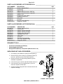
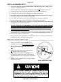
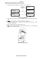
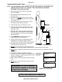
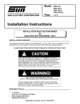
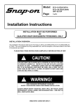
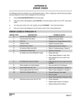
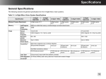
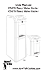
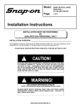
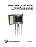
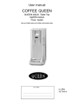
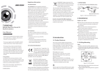
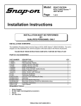
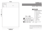
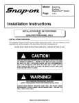
SUN ELECTRIC
Model:
SUN KOOL KARE
R-12/R-134a
UNIT SETUP
Page:
1 of 5
Installation Instructions
INSTALLATION MUST BE PERFORMED
BY
QUALIFIED SUN PERSONNEL ONLY
INSTALLATION OVERVIEW: _____________________________________________
The Installation Procedures listed are for the SUN KOOL KARE units (EEAC101A for R-12 & EEAC104A
for R-134a). The unit is shipped as a fully assembled unit, with the exception of the items listed in the
Parts & Accessories List per tester.
PLEASE READ THESE INSTRUCTIONS COMPLETELY BEFORE SETTING UP UNIT
!
THIS UNIT MUST BE PLUGGED INTO A PROPER AC OUTLET FOR UNIT
TO OPERATE CORRECTLY. REFER TO THE UNIT ID PLATE LOCATED
ON BACK OF UNIT. EXTENSION CORDS ARE NOT RECOMMENDED,
BUT IF AN EXTENSION CORD MUST BE USED, USE A CORD THAT IS
LESS THAN 50 FEET WITH A 16 AWG, OR ABOVE 50 FEET AND LESS
THAN 100 FEET WITH A 14 AWG.
!
USE STANDARD REFRIGERANT HANDLING
SAFETY PROCEDURES WHEN PERFORMING INSTALLATION
ALWAYS WEAR SAFETY GOGGLES, DON’T SPILL OR TOUCH LIQUID
REFRIGERANT, AVOID FLAMES, AND EXCESSIVE HEAT. USE ONLY IN
WELL VENTILATED AREA.
0692-2398-01 (06/03/97) REV. A
Page 2 of 5
PARTS & ACCESSORIES LIST FOR EEAC101A: ____________________________
PART NUMBER
0001006701
0119038601
0647019601
0647019701
0647019901
0647020001
0692183401
0692239801
0692239301
4211000101
7009244703
EAH0013C00A
DESCRIPTION
Wrench, Separator Bowl
Literature Kit
Adapter, GM
Adapter, Quick-Disconnect, GM/Ford
Adapter, Quick-Disconnect, Large GM
Adapter, Ford
Questionnaire, SEL 1403C
Installation instructions
Video Tape
Envelope
Recovery Tank Assembly
Gauge Set, Uniweld
QTY
1
1
1
1
1
1
1
1
1
1
1
1
PARTS & ACCESSORIES LIST FOR EEAC104A: ____________________________
PART NUMBER
0001006701
0119038601
0647028709
0647028710
0692183401
0692239801
0692239301
4211000101
7009244701
ARG04040
EAH0014C01A
DESCRIPTION
Wrench, Separator Bowl
Literature Kit
Adapter, Vehicle, High Side
Adapter, Vehicle, Low Side
Questionnaire, SEL 1403C
Installation Instructions
Video Tape
Envelope
Recovery Tank Assembly
Kit, Vehicle Adapter O-Ring
Gauge Set, R134a
QTY
1
1
1
1
1
1
1
1
1
1
1
REQUIRED TOOLS: ____________________________________________________
ù
ù
ù
Screwdriver (Flat Blade and Phillips)
Safety Goggles (0001-5005)
Refrigerant Oil (Mineral) or Superlube (0681-0193-02 or -03)
UNPACKING UNIT AND ACCESSORIES: ___________________________________
1. Cut Straps (A), and slide the carton (B) off the pallet (C).
A
2. Remove the top of the carton (D), and packing foam (E)
from unit. Split the corners of the base carton (F).
D
E
3. Remove all boxes (G) and packing material (H) from
scale/tank compartment.
G
5. Lean one side of unit (I) so packing foam (J) can be
removed. Repeat for other side.
B
H
4. Lean the unit (I) so it can be rolled off the base carton (F).
PL
AC
ED
OV
ER
SC
AL
E
6. Inventory all items using the Parts & Accessories list and
inspect for damage.
I
J
F
C
FIGURE 1 UNIT PACKAGE
0692-2398-01 (06/03/97) REV. A
Page 3 of 5
PARTS & ACCESSORIES SETUP: ________________________________________
1. Remove the Gauge Set Assembly (EAH0013C00A or EAC0014C01A) from the gauge set box
and place on gauge set bracket.
2. Remove the Blue and Red Hoses from the gauge set box and OIL the seals on each end.
3. Connect the open end of the Blue and Red Hoses to the Gauge Set respectively.
4. For the EEAC101A, place the four adapters in the Storage Compartment.
5. For the EEAC104A, connect the Red and Blue adapters (0647028709 and 0647028710) to the
Red and Blue Hoses from the Gauge Set respectively.
6. For the EEAC104A, place the O-Ring Kit (ARG04040) in the Storage Compartment.
7. Place the Separator Bowl Wrench (0001006701) in the Storage Compartment.
8. Remove the User's Manual from the Literature Kit, and place the remainder of the Literature Kit
(0119038601) in the Storage Compartment.
BE SURE TO REVIEW THE USER'S MANUAL WITH THE CUSTOMER DURING TRAINING.
Then before installing the User's Manual Envelope, ask where the customer would like
the envelope installed. There is also a Video Tape (0692239301) supplied and can be
viewed at the customer's convenience.
9. Peel the backing from the User's Manual Envelope (4211000101) and apply the envelope, with
the open end on top, to either side of the unit, or in the location designated by the customer.
10. Place the User's Manual in the Envelope.
11. Remove Recovery Tank (7009244701 or 7009244703) from it’s box. Remove cardboard wrap
from Recovery Tank. Set on floor in front of unit.
PREPARING NEW RECOVERY TANK: _____________________________________
1. Refering to FIGURE 2, open the BLUE valve on
Recovery Tank to release ALL COMPRESSED AIR.
2. Remove the Particle Filter from the Recovery Tank.
OIL seal, and re-attach to Recovery Tank. (BLUE
SIDE)
3. Remove the Yellow Hose from the gauge set box.
OIL the seals on each end of hose.
4. Attach open end of Yellow Hose to BLUE valve of
Recovery Tank. Attach other end of Yellow Hose to
service port on front of unit. Open ball valve on yellow
hose.
5. Plug AC Cord to a 115VAC outlet. Turn unit on using
the front power switch.
FIGURE 2 RECOVERY TANK
!
THIS UNIT MUST BE PLUGGED IN TO A PROPER AC OUTLET FOR
UNIT TO OPERATE CORRECTLY.
REFER TO UNIT ID PLATE
LOCATED ON BACK OF UNIT.
EXTENSION CORDS ARE NOT
RECOMMENDED, BUT IF AN EXTENSION CORD MUST BE USED, USE
A CORD THAT IS LESS THAN 50 FEET WITH A 16 AWG, OR ABOVE 50
FEET AND LESS THAN 100 FEET WITH A 14 AWG.
0692-2398-01 (06/03/97) REV. A
Page 4 of 5
PREPARING NEW RECOVERY TANK continued:
6. Following the displays in FIGURE 3, to program a 10 minute vacuum time.
STARTING
SCREEN
Enter time to pull
Vacuum on vehicle:
10 minutes
UP
DOWN
Enter time to hold
Vacuum:
00 minutes
UP
DOWN
YES
ENTER
Will you Recycle
from Vehicle this
sequence?
YES
Will you be pulling
a Vacuum this
sequence?
YES
NO
NO
Will you be charging
this sequence?
YES
ENTER
NO
FIGURE 3 VACUUM MODE
7. Once completed, close Recovery Tank valve (BLUE) and remove Yellow Hose from Recovery
Tank.
8. Re-OIL seal on Yellow Hose and connect to center port on Gauge Set.
9. Place Recovery Tank on scale. Tank fittings should face straight out the back of unit. Connect
velcro strap and tighten belt.
10. Remove bubble wrap from Red and Blue Hoses on unit
11. OIL seals on the anti-blow back valves on Red and Blue Hoses from unit. Connect respectively
to Recovery Tank. Refer to FIGURE 4
FIGURE 4 INSTALLING TANK
0692-2398-01 (06/03/97) REV. A
Page 5 of 5
CHARGING RECOVERY TANK: __________________________________________
NOTE: THIS PROCEDURE IS USED TO SETUP THE UNIT FOR CHARGING. RECOVERY TANK
SHOULD HAVE AT LEAST A 25” VACUUM. THIS PROCEDURE IS DONE WHEN
RECOVERY TANK IS ON THE SCALE
1. Be sure Recovery Tank valves (B) are closed.
Refer to FIGURE 5
2. Disconnect the Red and Blue hoses from the
Recovery Tank.
3. Disconnect and Re-Oil both the seals on Yellow
hose (C). Connect the long side of the Yellow Hose
to the Virgin Tank.
4. Connect the short side of the Yellow Hose to the
Red Valve on the Recovery Tank (B).
A
5. Open the Red Valve on the Recovery Tank.
6. Invert the Virgin Tank (A) and open valve. Open
Hand Valve (D) on the Yellow Hose to allow the
refrigerant to flow.
D
C
7. Raise the Virgin Tank to a higher level than the
Recovery Tank. Gravity and vacuum will transfer
the liquid refrigerant to the Recovery Tank faster
than reclaiming it.
8. Press <AMOUNT> to display the amount of
refrigerant that has been transferred.
9. After the desired amount of refrigerant has been
transferred, close valves on Virgin Tank and
Recovery Tank. Set Virgin Tank on ground upright.
10. Close Hand Valve on Yellow Hose. Disconnect
Yellow Hose from Recovery Tank.
B
FIGURE 5 CHARGING TANK
11. Re-Oil seals on anti-blow back valves on Red and
Blue Hoses from unit and connect to Recovery Tank. Open Recovery Tank valves.
12. Re-Oil seal on Yellow Hose and connect to service port on front of unit. Open Hand Valve on
Yellow Hose.
13. Following the displays in FIGURE 6, perform a
recover mode. This will reclaim the refrigerant from STARTING
the hose. (Optional: Opening Virgin Tank valve will SCREEN
reclaim rest of refrigerant.)
14. Once complete, disconnect Yellow Hose from Virgin
Tank.
Will you Recycle
from Vehicle this
sequence?
YES
Will you be pulling
a Vacuum this
sequence?
YES
15. Re-Oil seals on Yellow Hose and connect to center
port on Gauge Set.
NO
NO
Will you be charging
this sequence?
REMEMBER TO OIL O-RINGS
AND SEALS WHEN ATTACHING
HOSES OR FITTINGS
YES
FIGURE 6 RECOVER MODE
INSTALLATION COMPLETE/SETUP COMPLETE
0692-2398-01 (06/03/97) REV. A
NO