1
Chapter 2
Connection and Installation
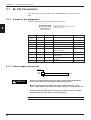
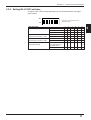
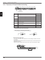
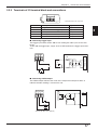
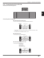
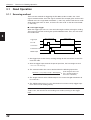
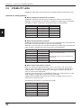
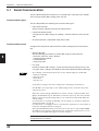
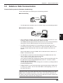
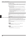
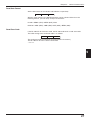
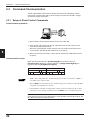
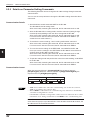
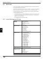
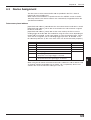
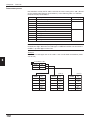
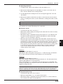
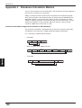
2.2.4 Terminals of I/O terminal block and wiring
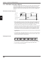
TIM
Trigger
input
2
+12V OUT– COM
OK
NG
SDA
Power supply OK/NG output
for sensors
(12 VDC, 300 mA)
SDB
SG
RDA
RDB
RS-422A/RS-485
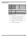
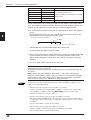
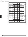
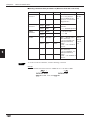
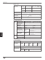
Symbol
Description
Signal direction
TIM
Trigger input
Input
Input
+12 V OUT- + terminal of power supply for sensor (12 VDC, 300 mA) Output
– terminal of power supply for sensor (0 V)
Output
COM
Common terminal for OK/NG output
—
OK
OK output
Output
NG
NG output
Output
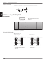
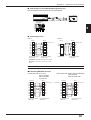
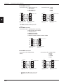
SDA
+ terminal for RS-422A data transmission/
RS-485 + terminal
Output,
Input/Output
SDB
– terminal for RS-422A data transmission/
RS-485 - terminal
Output,
Input/Output
SG
Signal ground
—
RDA
+ terminal for RS-422A data reception
Input
RDB
– terminal for RS-422A data reception
Input
*
Viewed from the left of the terminal block
•
•
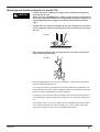
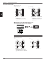
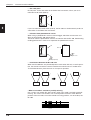
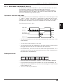
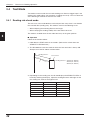
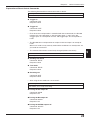
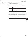
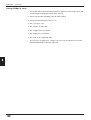
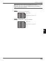
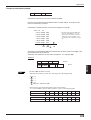
M3.0 screws are used for the terminal block.
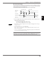
Use the following crimp terminals for connections.
Round-shape
Fork-shape
6.0 mm or
less
6.0 mm or
less
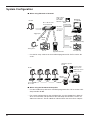
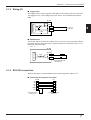
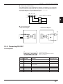
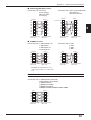
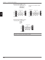
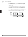
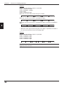
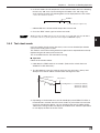
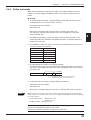
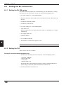
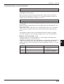
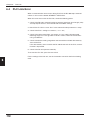
■ Connecting trigger input
The trigger input allows the BL-700 series to start reading bar codes (turn on the
laser beam).
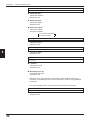
The trigger input is turned ON when 8.5 to 30 VDC input is activated between the
trigger input terminals.
The BL-U1 power supply for the sensor can be used as the input power supply.
TIM
+12V OUT–
Contact or
solid-state
+
+
8.5 to 30 VDC
10