1
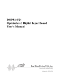
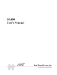
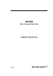
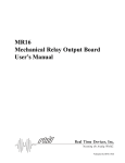
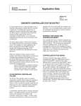
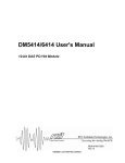
Mykerinos DUAL
Daughter card
User Manual
Version: DOC-1.1 (February 2009)
© 2009 Merging Technologies
Table of Contents
IMPORTANT NOTICE: ........................................................................................................................................... III
STATIC DANGER NOTICE: ................................................................................................................................... III
INFORMATION FOR THE USER: .......................................................................................................................... III
WARRANTY INFORMATION ......................................................................................................................................... IV
CONTACTING MERGING.............................................................................................................................................. IV
CHAPTER 1 – INTRODUCTION ...............................................................................................................................1
CARD FEATURES ..........................................................................................................................................................1
CARD OVERVIEW .........................................................................................................................................................1
CHAPTER 2 – INSTALLATION ................................................................................................................................2
MOUNTING THE DUAL DAUGHTER CARD ON MYKERINOS ...........................................................................................2
CONNECTING THE AES/EBU EXTENSION BRACKET .....................................................................................................2
INSTALLING THE MYKERINOS-DUAL CARD ON YOUR COMPUTER ...............................................................................2
CHAPTER 3 – BRACKET CONNECTIONS ............................................................................................................3
BRACKET CONNECTORS ................................................................................................................................................3
MYKERINOS MONITOR OUTPUT ...................................................................................................................................3
MYKERINOS VIDEO/TC I/O ..........................................................................................................................................3
DUAL ANALOG I/O .....................................................................................................................................................4
DUAL AES/EBU I/O...................................................................................................................................................4
CHAPTER 4 – SOFTWARE SETTINGS ...................................................................................................................5
REFERENCE SELECTION ................................................................................................................................................5
INPUT GAIN SELECTION................................................................................................................................................6
MIC/LINE SELECTION ...................................................................................................................................................6
48V SELECTION ............................................................................................................................................................6
MICPREAMP GAIN SELECTION .....................................................................................................................................6
OUTPUT GAIN SELECTION ............................................................................................................................................6
OUTPUT MUTE SELECTION ...........................................................................................................................................6
CHAPTER 5 – TYPICAL AUDIO SETUP .................................................................................................................7
APPENDIX 1 – TECHNICAL SPECIFICATIONS ...................................................................................................8
ANALOG LINE INPUTS ..................................................................................................................................................8
MICROPHONE PREAMPLIFIERS ......................................................................................................................................8
ANALOG LINE OUTPUTS ...............................................................................................................................................8
AES/EBU INPUTS ........................................................................................................................................................8
AES/EBU OUTPUTS .....................................................................................................................................................8
APPENDIX 2 –BLOC DIAGRAM ..............................................................................................................................9
APPENDIX 3 – BREAKOUT CABLES SPECIFICATION ...................................................................................10
BREAKOUT CABLES CONNECTORS ..............................................................................................................................10
ANALOG I/O BREAKOUT CABLE ..................................................................................................................................10
AES/EBU I/O BREAKOUT CABLE ...............................................................................................................................10
ii
Mykerinos DUAL Daughter card User Manual
© 2009 Merging Technologies
IMPORTANT NOTICE:
Please read the following information very carefully before attempting any installation. Failure to comply with
the precise instructions may result in damage to your Merging hardware. Please read this entire section of the
manual carefully before installation.
STATIC DANGER NOTICE:
Please note that the DUAL Daughter card contains delicate electronic components that can be damaged or
even destroyed when exposed to static electricity. Take all necessary precautions not to discharge static
electricity when touching any of the DUAL Daughter car components.
INFORMATION FOR THE USER:
Mykerinos and its daughter card comply with the following specifications:
EMC Emmisons
EN 55022 : 1994 /A1 : 1995 /A2 : 1997 Class A ITE emissions requirements (EU)
FCC 47 CFR Part 15 Class A emissions requirements (USA)
EMC Immunity
EN 50082-1: 1992 EMC residential, commercial and light industrial generic immunity standard.
FCC Notice
This product has been tested and found to comply with the limits for a Class A digital device, pursuant to Part 15 of
the FCC rules. Operation is subject to the following two conditions: (1) This device may not cause harmful
interference, and (2) This device must accept any interference received, including interference that may cause
undesired operation.
These limits are designed for providing reasonable protection against harmful interference in a residential installation.
This equipment generates, uses and can radiate radio frequency energy and, if not installed and used in accordance
with the instructions contained in this manual, may cause harmful interference to radio and television
communications. However, there is no guarantee that interference will not occur in a particular installation.
NOTE: Connecting this device to peripheral devices that do not comply with CLASS A requirements or using an
unshielded peripheral data cable could also result in harmful interference to radio or television reception. The user is
cautioned that any changes or modifications not expressly approved by the party responsible for compliance could
void the user’s authority to operate this equipment. To ensure that the use of this product does not contribute to
interference, it is necessary to use shielded I/O cables.
CE Notice
Such a
•
•
marking is indicative that this system’s devices meet the following applicable technical standards:
EN 55022 – “Information Technology Equipment - Radio disturbance characteristics Limits and methods of
measurement”
EN 50082-1: 1992 – “Electromagnetic compatibility – Generic immunity standard Part 1:Residential,
commercial, and light industry”
This product is classified for use in a typical Class A commercial environment, and is not designed or intended for
use in other EMC environments. The user of this product is obliged for proper use and installation of the product and
for taking all steps necessary to remove sources of interference to telecommunications or other devices.
© 2009 Merging Technologies
Mykerinos DUAL Daughter card User Manual
iii
Warranty Information
This product is warranted to be free of defects in materials and workmanship for a period of one year from the date of
purchase. Merging Technologies, Inc. extends this Limited Warranty to the original purchaser.
In the event of a defect or failure to confirm to this Limited warranty, Merging Technologies, Inc. will repair or
replace the product without charge within sixty (60) days. In order to make a claim under this limited warranty, the
purchaser must notify Merging Technologies, Inc. or their representative in writing, of the product failure. In this
limited warranty the customer must upon Merging Technologies, Inc. request, return the product to the place of
purchase, or other local designation, for the necessary repairs to be performed. If the consumer is not satisfied with
the repair, Merging Technologies, Inc. will have the option to either attempt a further repair, or refund the purchase
price.
This warranty does not cover: (1) Products which have been subject to misuse, abuse, accident, physical damage,
neglect, exposure to fire, water or excessive changes in the climate or temperature, or operation outside maximum
rating. (2) Products on which warranty stickers or product serial numbers have been removed, altered or rendered
illegible. (3) The cost of installations, removal or reinstallation. (4) Damages caused to any other products.
Contacting Merging
For all general or sales inquiries:
In Europe, Africa and Asia contact our Swiss Office:
Merging Technologies SA
Le Verney 4
1070 Puidoux
Switzerland
Phone: +41 21 946 0444
Fax:
+41 21 946 0445
In the Americas, contact our US Office:
Independent Audio, Inc.
43 Deerfield Road
Portland, ME 04101-1805
United States of America
Phone: +1 207 773 2424
Fax:
+1 207 773 2422
Merging website: www.merging.com
iv
Mykerinos DUAL Daughter card User Manual
© 2009 Merging Technologies
Chapter 1 – Introduction
Congratulations on your Mykerinos DUAL Daughter card purchase. The Dual DC is the most cost-effective I/O
daughter card for Pyramix, Incite Studio and SOFTIMAGE®|DS users, as well as for OEMs.
It is an ideal I/O solution for mixed analog/digital requirements, as encountered in Broadcast production, and
Video/Film post-production environments. It allows the direct connecting of up to two electrodynamic or condenser
microphones, typically for quick and easy voice-over recording.
Card Features
•
Up to 12 inputs and 12 outputs on a single board:
>
>
>
>
>
•
2 CH Analog Mic/Line inputs
2 CH Analog Line inputs
4 CH Analog Line outputs
8 CH AES/EBU inputs
8 CH AES/EBU outputs
All audio connections are made using high-quality balanced XLR type connectors,
provided by two DB-25 break-out cables.
•
High quality 24 bit A/D and D/A using the latest generation in converter technology.
•
2 built-in microphone preamplifiers, with a selection MIC / LINE available on analog inputs 1 and 2.
•
Built-in 48V microphone phantom power.
•
Analog input and output level adjustment offering 24 dB range to accommodate all standard studio levels.
•
High common mode rejection balanced input circuitry on all analog inputs, for optimum rejection of power line
hum, RF interference, voltage drops and other externally generated noise commonly encountered with long audio
cable runs.
•
High quality balance output circuitry on all analog outputs, for maximum output signal balance ratio
performance, even under adverse asymmetrical loads.
•
Support for sampling rates 32 kHz, 44.1 kHz or 48 kHz.
•
High cost-effectiveness.
Card Overview
Mezzanine connector 64-pin,
to Mykerinos board.
Connector 30-pin,
to the optional HDTDM bus cable.
Connector 26-pin,
to DB25 AES/EBU Extension
bracket cable
© 2009 Merging Technologies
Connector DB25,
to Analog I/O
breakout cable.
Mykerinos DUAL Daughter card User Manual
1
Chapter 2 – Installation
Mounting the DUAL daughter card on Mykerinos
If your DUAL Daughter card is already assembled with your Mykerinos board, you can jump to the next point.
To change your Mykerinos Daughter card:
Remove the daughter card to be changed, if any
If necessary, remove the Mykerinos bracket,
Mount in its place the bracket shipped along with your DUAL Daughter card,
Place your DUAL Daughter card on Mykerinos:
- First insert the Analog I/O DB25 connector into its corresponding bracket opening,
- Then place the Mezzanine connector carefully in front of its corresponding connector on Mykerinos,
- Gently press the two boards against each other, until the connectors are tightly fitted,
- Mount the 4 screws correctly to ensure a good electrical connection between both boards.
Connecting the AES/EBU extension Bracket
Plug your DB25 AES/EBU Extension bracket cable into the corresponding 26-pin connector on the rear of your
Mykerinos-DUAL PCI card.
Installing the Mykerinos-DUAL card on your computer
You need to find two free slots to install the Mykerinos-DUAL board and its AES/EBU Extension bracket:
The Mykerinos-DUAL board need a free PCI slot,
The AES/EBU Extension bracket can be placed on any free slot,
You can also mount it on any DB25 opening available in your PC Box, in case you are short of free slot.
Correctly mount the brackets and DB25 screws, to ensure a good electrical connection to the PC Box.
2
Mykerinos DUAL Daughter card User Manual
© 2009 Merging Technologies
Chapter 3 – Bracket Connections
Bracket connectors
The following figure represents the Mykerinos bracket when combined with the DUAL Daughter card,
and the DUAL AES/EBU Extension bracket.
Mykerinos Monitor Output,
Jack connector.
Mykerinos Video/TC I/O,
Mini-Din connector.
DUAL Analog I/O,
DB25 connector.
DUAL AES/EBU I/O,
DB25 connector.
Mykerinos-DUAL
Bracket
DUAL AES/EBU
Extension Bracket
Mykerinos Monitor Output
This is the unbalanced stereo output corresponding to the “Monitor Jack” Left / Right output channels of your mixer.
Any headphone or preamplifier can be connected to this output.
See “Mykerinos User Manual” for detailed information on the Monitor Output.
Mykerinos Video/TC I/O
This 9-pin Mini-Din connector is for the Mykerinos Video/TC breakout cable.
The breakout cable allows Mykerinos to lock to a video “house sync” or a Wordclock reference, read & generate
VITC and read & generate LTC. This option also adds the capability to "burn" a Time code "insert" in the video
output signal. This interface has provision for one BNC input CVS1In, one BNC Input/Output CVS2In/WCK, one
BNC output CVS Out, one XLR Female for LTC input and one XLR Male for LTC output.
See “Mykerinos User Manual” for detailed information on the Video/TC I/O.
© 2009 Merging Technologies
Mykerinos DUAL Daughter card User Manual
3
DUAL Analog I/O
This DB25 connector is for the DUAL Analog I/O breakout cable, as shown in the following drawing.
See Appendix 3 for detailed information on breakout cables.
ANALOG IN 1 - 4
Any professional level balanced audio output can be connected to the analog line inputs of the DUAL Daughter card.
Input levels are selectable from consumer level (–10 dBV) up to professional level (+4 dBu).
See chapter 4 on how to adjust the Analog Input Levels.
ANALOG OUT 1 - 4
Any professional level balanced audio input can be connected to the analog line outputs of the DUAL Daughter card.
Output levels are selectable from consumer level (–10 dBV) up to professional level (+4 dBu).
See chapter 4 on how to adjust the Analog Output Levels.
DUAL AES/EBU I/O
This DB25 connector is for the DUAL AES/EBU I/O breakout cable, as shown in the following drawing.
See Appendix 3 for detailed information on breakout cables.
AES/EBU IN 1/2 - 7/8
Any professional level balanced digital AES/EBU audio output sources at 32, 44.1 or 48 KHz can be connected to the
AES/EBU inputs of the DUAL Daughter card.
AES/EBU OUT 1/2 - 7/8
Any professional level balanced digital AES/EBU audio inputs at 32, 44.1 or 48 KHz can be connected to the
AES/EBU outputs of the DUAL Daughter card.
4
Mykerinos DUAL Daughter card User Manual
© 2009 Merging Technologies
Chapter 4 – Software Settings
To access the DUAL Software Settings:
- Open the “Mixer Settings” panel.
-
Select the “DUAL(#10xxx)” tab.
The following settings panel appears:
Reference Selection
This field allows the selection of the “Audio Input” sync source.
When “Audio Input” is selected as sync source in “I/O & Sync” tab, DUAL wills chose the AES/EBU input to which
synchronize depending on the sync mode selected.
There are five possible sync modes:
-
AUTO
AES/EBU (1/2)
AES/EBU (3/4)
AES/EBU (5/6)
AES/EBU (7/8)
While in AUTO mode, DUAL automatically detects and switches to a valid AES/EBU sync source.
In the four other modes, DUAL always tries to synchronize to the specified input. It never switches to another input,
even when the selected sync source becomes invalid.
© 2009 Merging Technologies
Mykerinos DUAL Daughter card User Manual
5
Input Gain Selection
This section allows analog input level adjustment.
To accommodate your external devices output levels, you can change the input level of each analog input
within a range of –12 dB to +12 dB.
A gain of –12 dB will result in a +20 dBu full scale input level.
A gain of +12 dB will result in a -4 dBu full scale input level.
Mic/Line Selection
This section allows the enabling of the microphone preamplifier.
This option is available on analog inputs 1 and 2 only.
Check this option if you want to connect an electrodynamic or a condenser microphone to the corresponding input.
48V Selection
This section allows the enabling of the 48V phantom power.
This option is available only if the “Mic/Line” option is selected on the corresponding input.
Check this option if you want to connect a 48V condenser microphone to the corresponding input.
MicPreamp Gain Selection
This section allows the selection of the microphone preamplifier gain.
This option is available only if the “Mic/Line” option is selected on the corresponding input.
You can select 0 dB, +20 dB or +40 dB, depending on your microphone sensitivity.
Output Gain Selection
This section allows analog output level adjustment.
To accommodate your external devices input levels, you can change the output level of each analog output
within a range of –24 dB to 0 dB.
A gain of –24 dB will result in a -6 dBu full scale output level.
A gain of 0 dB will result in a +18 dBu full scale output level.
Output Mute Selection
This section allows the enabling of the analog output mute.
Selecting this option make sure that the corresponding analog output will always be muted, even if your mixer routes
audio to this output.
6
Mykerinos DUAL Daughter card User Manual
© 2009 Merging Technologies
Chapter 5 – Typical Audio Setup
This section displays typical audio connections for Merging Mykerinos-DUAL in a Video environment.
VIDEO Reference
Black Burst generator
Audio / Video
Workstation
VIDEO I/O
PCI board
ANALOG IN 1
Microphone
ANALOG IN 2
Microphone
ANALOG IN 3
Mykerinos-DUAL
PCI board
ANALOG IN 4
Left Out
Analog Tape
Right Out
ANALOG I/O
DUAL AES/EBU
Extension bracket
ANALOG OUT 1
Left
ANALOG OUT 2
Right
ANALOG OUT 3
Center
ANALOG OUT 4
Sub-bass
Surround
Monitoring
System
Rear Left
Mykerinos Monitoring Output
Rear Right
Video Sync IN
AES/EBU IN 1/2
AES/EBU OUT 1/2
AES/EBU IN 3/4
AES/EBU OUT 3/4
AES/EBU IN 5/6
AES/EBU IN 1/2
AES/EBU IN 7/8
AES/EBU IN 3/4
Sony
Digital BetaCam
Video Deck
AES/EBU I/O
AES/EBU OUT 1/2
AES/EBU OUT
DAT
AES/EBU OUT 3/4
AES/EBU IN
AES/EBU OUT 5/6
AES/EBU OUT 7/8
AES/EBU OUT
AES/EBU IN
Digital
Effect
This example uses the following:
•
Digital BetaCam AES/EBU outputs are connected to DUAL AES/EBU IN 1/2 and 3/4.
•
DUAL AES/EBU OUT 1/2 and 3/4 are connected to Digital BetaCam AES/EBU inputs.
•
The DAT AES/EBU output is connected to DUAL AES/EBU IN 5/6.
•
DUAL AES/EBU OUT 5/6 is connected to the DAT AES/EBU input.
•
The Digital Effect AES/EBU output is connected to DUAL AES/EBU IN 7/8.
•
DUAL AES/EBU OUT 7/8 is connected to the Digital Effect AES/EBU input.
•
Two Microphones are connected to DUAL Analog IN 1 and 2.
•
An analog stereo tape or a camera is connected to DUAL Analog IN 3 and 4.
•
The Surround Monitoring system uses DUAL Analog OUT 1-4 for the Left, Right, Center and Sub-Bass
channels. The Rear Left and Rear Right channels are provided by the Mykerinos Monitoring Output.
•
The Mykerinos card (via the VIDEO/TC breakout cable), the Video I/O card and the Video Deck are connected
to the Video Reference “Black Burst” generator.
Note that each device should be connected to the video generator with its own cable.
Using the Loop-Through to connect the different devices is not recommended.
•
The Mykerinos is set to lock to “Video”, or “Audio Input” with DUAL configured in “AUTO” sync mode.
© 2009 Merging Technologies
Mykerinos DUAL Daughter card User Manual
7
Appendix 1 – Technical Specifications
Parameter
Power Consumption
Conditions
+3.3V
+5V
+12V
-12V
Value
< 100
< 200
< 300
< 100
Unit
mA
mA
mA
mA
Conditions
Value
24
48
-4
+20
102
98
-93
± 0.1
>13
>40
>100
Unit
Bits
KHz
dBu
dBu
dB(A)
dB
dB
dB
KOhms
dB
dB
Value
102
96
77
+48
>3
Unit
dB(A)
dB(A)
dB(A)
V
KOhms
Value
24
48
-6
+18
97
95
-93
± 0.1
<50
>40
>100
Unit
Bits
KHz
dBu
dBu
dB(A)
dB
dB
dB
Ohms
dB
dB
Value
24
48
110
Unit
Bit
KHz
Ohms
Analog Line Inputs
Parameter
Resolution
Max. Sample Rate
Min. Full Scale Input Level
Max. Full Scale Input Level
Dynamic Range
THD+N
Frequency Response
Input Impedance
Common Mode Rejection
Interchannel Isolation (Crosstalk)
A-weighted
20Hz-20kHz
1 kHz @ -1 dBFS = +17 dBu
20Hz-20kHz
Differential
1kHz
Microphone Preamplifiers
Parameter
Dynamic Range
(Including A/D converter)
Phantom Power selection
Input Impedance
Conditions
Gain = 0 dB (A-weighted)
Gain = +20 dB (A-weighted)
Gain = +40 dB (A-weighted)
Differential
Analog Line Outputs
Parameter
Resolution
Max. Sample Rate
Min. Full Scale Output Level
Max. Full Scale Output Level
Dynamic Range
THD+N
Frequency Response
Output Impedance
Output Balance Ratio
Interchannel Isolation (Crosstalk)
Conditions
A-weighted
Unweighted
1 kHz @ -1 dBFS = +17 dBu
20Hz-20kHz
Differential
1kHz
AES/EBU Inputs
Parameter
Resolution
Max. Sample Rate
Input Impedance
Conditions
Differential
AES/EBU Outputs
Parameter
Resolution
Max. Sample Rate
Output Impedance
Conditions
Differential
Value
24
48
110
Unit
Bit
KHz
Ohms
Note: All specifications subject to change without notice.
8
Mykerinos DUAL Daughter card User Manual
© 2009 Merging Technologies
© 2009 Merging Technologies
AES/EBU 7/8
Encoder
AES/EBU 5/6
Encoder
AES/EBU 3/4
Encoder
AES/EBU 1/2
Encoder
AES/EBU 7/8
Line Driver
AES/EBU 5/6
Line Driver
AES/EBU 3/4
Line Driver
AES/EBU 1/2
Line Driver
AES/EBU 5/6
Decoder
AES/EBU 5/6
Line Receiver
64 audio input channels
AES/EBU 7/8
Decoder
AES/EBU 3/4
Decoder
AES/EBU 3/4
Line Receiver
Sync & Contol I/O
AES/EBU 7/8
Line Receiver
AES/EBU 1/2
Decoder
AES/EBU 1/2
Line Receiver
Mezzanine connector 64-pin,
to Mykerinos board.
Power Supplies
Sync & Contol I/O
Audio Routing
64 audio output channels
Sync & Control
64 audio input channels
64 audio output channels
Mykerinos DUAL Daughter card User Manual
Connector 30-pin,
to the optional HDTDM bus cable.
Output Gain
CH3
Output Gain
CH4
Input Gain
CH1
Input Gain
CH2
Input Gain
CH3
D/A
CH3
D/A
CH4
A/D
CH1
A/D
CH2
A/D
CH3
Input Gain
CH4
Output Gain
CH2
D/A
CH2
A/D
CH4
Output Gain
CH1
D/A
CH1
48V Phantom Power
Regulation.
Line Input
CH4
Line Input
CH3
Line Input
CH2
Line Input
CH1
Output Filter
CH4
Output Filter
CH3
Output Filter
CH2
Output Filter
CH1
Analog Power Supplies
Regulation.
Microphone
preamplifier CH2
Microphone
preamplifier CH1
Line Output
CH4
Line Output
CH3
Line Output
CH2
Line Output
CH1
Appendix 2 –Bloc Diagram
Connector DB25,
to Analog I/O
breakout cable.
Connector 26-pin,
to DB25 AES/EBU
Extension bracket cable.
9
Appendix 3 – Breakout cables Specification
Breakout cables connectors
1
13
14
25
DB25 Male Connector (I/O)
2
1
1
3
XLR Female Connector (Inputs)
2
3
XLR Male Connector (Outputs)
Analog I/O breakout cable
XLR Label
XLR color Signal XLR-F DB25-M
ANALOG IN 1 BROWN
ANALOG IN 2 RED
ANALOG IN 3 ORANGE
ANALOG IN 4 YELLOW
AGND
1
9
AIN1+
2
13
AIN1-
3
25
AGND
1
21
AIN2+
2
12
AIN2-
3
24
AGND
1
8
AIN3+
2
11
XLR Label
Cable Color
ANALOG OUT 1 GREEN
ANALOG OUT 2 BLUE
ANALOG OUT 3 PURPLE
Signal
XLR-M DB25-M
AGND
1
5
AOUT1+
2
1
AOUT1-
3
14
AGND
1
18
AOUT2+
2
2
AOUT2-
3
15
AGND
1
6
AOUT3+
2
3
AIN3-
3
23
AOUT3-
3
16
AGND
1
20
AGND
1
19
AIN4+
2
10
AOUT4+
2
4
AIN4-
3
22
AOUT4-
3
17
ANALOG OUT 4 GRAY
Note: The DB25 pin 7 is connected to AGND.
AES/EBU I/O breakout cable
XLR Label
XLR Color
Signal
DGND
AES/EBU IN 1/2 BROWN
AES/EBU IN 3/4 RED
AES/EBU IN 5/6 ORANGE
AES/EBU IN 7/8 YELLOW
XLR-F DB25-M
1
XLR Label
XLR Color
9
Signal
XLR-M DB25-M
DGND
5
DIN1/2+
2
13
DOUT1/2+
2
1
DIN1/2-
3
25
DOUT1/2-
3
14
DGND
1
21
DGND
1
18
DIN3/4+
2
12
DIN3/4-
3
24
DGND
1
8
DIN5/6+
2
11
AES/EBU OUT 1/2 GREEN
1
AES/EBU OUT 3/4 BLUE
AES/EBU OUT 5/6 PURPLE
DOUT3/4+
2
2
DOUT3/4-
3
15
DGND
1
6
DOUT5/6+
2
3
DIN5/6-
3
23
DOUT5/6-
3
16
DGND
1
20
DGND
1
19
DIN7/8+
2
10
DOUT7/8+
2
4
DIN7/8-
3
22
DOUT7/8-
3
17
AES/EBU OUT 7/8 GRAY
Note: The DB25 pin 7 is connected to DGND.
10
Mykerinos DUAL Daughter card User Manual
© 2009 Merging Technologies