1
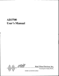
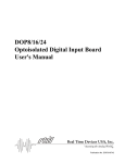
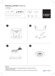
MR16 Mechanical Relay Output Board User’s Manual ® Real Time Devices, Inc. Accessing the Analog World® Publication No. MR16 - 9738 MR16 User’s Manual ® REAL TIME DEVICES, INC. Post Office Box 906 State College, Pennsylvania 16804 Phone: (814) 234-8087 FAX: (814) 234-5218 Published by Real Time Devices, Inc. P.O. Box 906 State College, PA 16804 Copyright © 1997 by Real Time Devices, Inc. All rights reserved Printed in U.S.A. INTRODUCTION The MR16 mechanical relay output board provides 16 electromechanical single-pole, double-throw relays for general-purpose switching applications. Driven by 16 digital output lines available on many Real Time Devices’ PC data acquisition and control boards, the MR16 features: • • • • • 16 SPDT relays with 120-volt/1A rating, On-board relay driver circuits, LED indicators to monitor relay activity, Single +5-volt power supply, On-board screw terminals for easy wiring. What Comes With Your Board You receive the following items in your MR16 package: • MR16 mechanical relay output board • User’s manual If any item is missing or damaged, please call Real Time Devices’ Customer Service Department at (814) 234-8087. If you require service outside the U.S., contact your local distributor. In addition to the items included in your MR16 package, Real Time Devices offers a full line of board accessories. Key accessories for the MR16 include the TB50 terminal board and the XB50 prototype/terminal board which can be connected to the daisy chain connector for prototype development and easy signal access. Using This Manual This manual is intended to help you get your new board running quickly, while also providing enough detail about the board and its functions so that you can enjoy maximum use of its features even in the most complex applications. We assume that you already have an understanding of data acquisition principles and that you can provide the software necessary to control the MR16 board. When You Need Help This documentation package should provide enough information for you to achieve your desired results. If you have any problems using this board, contact our Technical Support Department, (814) 234-8087, during regular business hours, eastern standard time or eastern daylight time, or send a FAX requesting assistance to (814) 234 5218. When sending a FAX request, please include your company’s name and address, your name, your telephone number, and a brief description of the problem. 1 2 MR16 DESCRIPTION Board Settings The MR16 board has jumper settings you can change if necessary for your application. The factory settings are listed in this section. Should you need to change these settings, use these easy-to-follow instructions. Figure 1 shows the board layout. Fig. 1 — MR16 Board Layout 3 P3 — Internal/External Power Source, +5 Volts (Factory Setting: +5V INT.) Header connector P3, shown in Figure 2, let you select the power source for the MR16. Each relay consumes about 33 mA when energized, so the maximum current requirement for all relays energized simultaneously is about 0.53 A. Taking this much current from the computer’s +5 volt power bus could overload the PC’s supply if you have other circuitry drawing high current (such as two or three MR16 boards daisy chained). P3 can be used to jumper to an external +5 volt power supply. The external power sources are connected to the MR16 board at TB4, located to the left of P3. P3 +5 EXT. INT. Fig. 2 — Internal/External Power Source Jumper, P3 P5 Through P20 — Bypass/Normal Relay Operation (Factory Setting: NOR (Normal)) Header connectors P5 through P20 (P5 is shown in Figure 3) let you bypass an individual relay so that the digital output line can be brought out to the external I/O connector where it can be used for digital control functions. The jumper for each relay channel is factory installed across the NOR pins for normal relay operation (the digital output line controls the relay). To bypass the relay, move the jumper to the BYP pins and install a 0 ohm resistor (or jumper wire) in the corresponding resistor pads. R1 is the Channel 1 resistor pad, R2 is Channel 2, and so on through R16, as marked on the board. Note that you must move the jumper to BYP and install a 0 ohm resistor to bypass the relay. The relay channel diagram on page 6 shows this circuitry. P5 CH1 NOR BYP Fig. 3 — Bypass/Normal Relay Jumper, P5 Connecting to the PC Interface Board Connecting to a 50-pin Interface Board Figure 4 shows the MR16’s P1 I/O connector pinout, with all of the pins used by the MR16 board labeled. The MR16 is pin-for-pin compatible with all Real Time Devices’ 50-pin I/O connector boards. For these boards, all of the unlabeled pins on the MR16 carry the same signal found at the I/O connector of the interface board you are using. If you want to access other signals on your interface board, such as analog inputs and timer/counters, you can connect to the 16 signals available on TB3 at the top of the MR16 board. This terminal strip is labeled with the pin numbers brought out to it from the 50-pin connector. To find the signals available on these pins, refer to the interface board’s pinout. To further expand the number of relays you can control using your digital I/O lines, you can use the daisy chain connector on the MR16 board, P2. The signals at this connector are identical to the pinout of your 50-pin interface board. You can connect to another MR16 (each digital output line will now control two relays, one on each MR16 board), or to a TB50 or XB50 breakout board to easily access all of the interface board signals. Our technical staff will gladly help you select the accessories you need for your application. 4 1 2 3 4 5 6 7 8 9 10 11 12 13 14 15 16 17 18 19 20 21 22 DI N 1 5 23 24 DIN 7 DI N 1 4 25 26 DIN 6 DI N 1 3 27 28 DIN 5 DI N 1 2 29 30 DIN 4 DI N 1 1 31 32 DIN 3 DI N 1 0 33 34 DIN 2 DI N 9 35 36 DIN 1 DI N 8 37 38 DIN 0 39 40 41 42 43 44 45 46 + 1 2 VOLT S 47 48 +5 VOLTS 49 50 DIGITA L GND Fig. 4 — P1 I/O Connector Pin Assignments Connecting to a 40-pin A/D Converter Board The MR16 can be adapted for use with all Real Time Devices’ 40-pin interface boards by making I/O connections using an RTD Discrete Wire Kit. Available with single or twisted pair wiring, this kit is designed so that you can mate connectors with otherwise incompatible pinouts. Using Figure 4 and the pinout diagram for your interface board, you can make the appropriate connections. Connecting to the Signal Sources One digital output line from the A/D interface board is required to control each relay. These lines are labeled DIN0 through DIN15 on the MR16 P1 connector pinout because they are inputs to the MR16 board. These lines are programmed through the A/D interface board. When selecting normally open operation of a relay, the relay is open when the control line is low and closed when the control line is high. In normally closed operation, the relay is closed when the control line is low and open when the control line is high. When the relay is energized, its LED status indicator light will be on. The MR16 cannot be controlled by analog lines! If your interface board’s digital I/O is provided by an 8255 programmable peripheral interface (PPI), then you must set up the lines that you use for the MR16 as mode 0 outputs. The interface board manual tells you how to set up the PPI. TB1 and TB2 are 25-terminal miniature screw terminal strips which let you easily connect and disconnect the relay outputs to external devices. When operating the relay as a normally open switch (open = low and closed = high), connect the external device the relay is controlling to the NO terminal screw and the ground to the COM terminal screw for the selected channel. When operating the relay as a normally closed switch (closed = low and open = high), connect the external device to the NC terminal screw and the ground to the COM screw terminal. An additional ground terminal is provided on each strip for your convenience when making these connections. Figure 5 shows a diagram of the channel 1 (DIN0) relay circuit. 5 CHANNEL 1 BYP COM +5V NC NO +5V NOR DIN0 CHANNEL 1 LED +5V BYP Fig. 5 — MR16 Relay Circuit Diagram 6 APPENDIX A MR16 SPECIFICATIONS A-1 A-2 MR16 Characteristics Typical @ 25° C Relay Type ...................................................................................................... SPDT (Form C) Contact rating ..................................................................................... 120 Vac/Vdc, 1 A Breakdown voltage ............................................................................ 500 Vac/Vdc, min ‘ON’ time ...................................................................................................... 3 msec, typ ‘OFF’ time .................................................................................................... 2 msec, typ Switching time ........................................................................................... 10 msec, typ Insulation resistance ........................................................................................ >100 Mý Life expectancy ..................................................... over 5 million operations at full load Current Requirements +5 volts (33 mA per relay, energized) .................................................................... .53A Power Requirements +5 volts ....................................................... From computer or external power supplies Connectors Two 50-pin shrouded headers with ejector tabs Screw Terminals TB1 and TB2 - 25-terminal; TB3 - 16-terminal; TB4 - 3-terminal 22-12 AWG wire Size 6.875"L x 5.0"W (175mm x 127mm) A-3 A-4 APPENDIX B RTD INTERFACE BOARD PINOUTS B-1 B-2 ADA3100 Pinout: DIFF. S.E. DIFF. S.E. AIN1+ AIN1 1 2 AIN1- ANAL OG GND A IN2+ A IN2 3 4 A IN2- A NA L OG GND A IN3+ A IN3 5 6 A IN3- A NA L OG GND A IN4+ A IN4 7 8 A IN4- A NA L OG GND A IN5+ A IN5 9 10 A IN5- A NA L OG GND A IN6+ A IN6 11 12 A IN6- A NA L OG GND A IN7+ A IN7 13 14 A IN7- A NA L OG GND A IN8+ A IN8 15 16 A IN8- A NA L OG GND AOUT1 17 18 A NA L OG GND AOUT2 19 20 A NA L OG GND A NA L OG GND 21 22 A NA L OG GND DIN7 23 24 DOUT7 DIN6 25 26 DOUT6 DIN5 27 28 DOUT5 DIN4 29 30 DOUT4 DIN3 31 32 DOUT3 DIN2 33 34 DOUT2 DIN1 35 36 DOUT1 DIN0 37 38 DOUT0 TRIGGER IN 39 40 DIGITA L GND EXT PACER CL K 41 42 TIMER OUT TRIGGER OUT 43 44 COUNTER OUT EXT CL K 45 46 EXT GATE +12 VOLTS 47 48 +5 VOLTS -12 VOLTS 49 50 DIGITA L GND AD3700 Pinout: A I N1 1 2 ANAL OG GND A I N2 3 4 A NA L OG GND A I N3 5 6 A NA L OG GND A I N4 7 8 A NA L OG GND A I N5 9 10 A NA L OG GND A I N6 11 12 A NA L OG GND A I N7 13 14 A NA L OG GND A I N8 15 16 A NA L OG GND A NA L OG GND 17 18 A NA L OG GND A NA L OG GND 19 20 A NA L OG GND A NA L OG GND 21 22 A NA L OG GND DI N7 23 24 DOUT7 DI N6 25 26 DOUT6 DI N5 27 28 DOUT5 DI N4 29 30 DOUT4 DI N3 31 32 DOUT3 DI N2 33 34 DOUT2 DI N1 35 36 DOUT1 DI N0 37 38 DOUT0 T R I G GE R I N 39 40 DIGITA L GND EX T PAC E R CL K 41 42 TIMER OUT T R I G GE R O U T 43 44 COUNTER OUT EXT CL K 45 46 EXT GATE + 1 2 VO LT S 47 48 +5 VOLTS - 1 2 VO LT S 49 50 DIGITA L GND B-3 ADA900 Pinout: DIFF. S.E. DIFF. S.E. AIN1+ AIN1 1 2 AIN1- ANAL OG GND A IN2+ A IN2 3 4 A IN2- A NA L OG GND A IN3+ A IN3 5 6 A IN3- A NA L OG GND A IN4+ A IN4 7 8 A IN4- A NA L OG GND A NA L OG GND 9 10 A NA L OG GND A NA L OG GND 11 12 A NA L OG GND A NA L OG GND 13 14 A NA L OG GND A NA L OG GND 15 16 A NA L OG GND AOUT1 17 18 A NA L OG GND A NA L OG GND 19 20 A NA L OG GND A NA L OG GND 21 22 A NA L OG GND DIN7 23 24 DOUT7 DIN6 25 26 DOUT6 DIN5 27 28 DOUT5 DIN4 29 30 DOUT4 DIN3 31 32 DOUT3 DIN2 33 34 DOUT2 DIN1 35 36 DOUT1 DIN0 37 38 DOUT0 TRIGGER IN 39 40 DIGITA L GND DIGITA L GND 41 42 DIGITA L GND TRIGGER OUT 43 44 COUNTER OUT EXT CL K 45 46 EXT GATE +12 VOLTS 47 48 +5 VOLTS -12 VOLTS 49 50 DIGITA L GND DM402 Pinout: AIN1 1 2 ANALOG GND AIN2 3 4 ANALOG GND AIN3 5 6 ANALOG GND AIN4 7 8 ANALOG GND AIN5 9 10 ANALOG GND AIN6 11 12 ANALOG GND AIN7 13 14 ANALOG GND AIN8 15 16 ANALOG GND AOUT 1 17 18 ANALOG GND AOUT 2 19 20 ANALOG GND ANALOG GND 21 22 ANALOG GND PA7 23 24 PC7 PA6 25 26 PC6 PA5 27 28 PC5 PA4 29 30 PC4 PA3 31 32 PC3 PA2 33 34 PC2 PA1 35 36 PC1 PA0 37 38 PC0 TRIGGER IN 39 40 DIGITAL GND EXT GATE 1 41 42 T/C OUT 1 TRIGGER OUT 43 44 T/C OUT 2 EXT CLK 45 46 EXT GATE 2 +12 VOLTS 47 48 +5 VOLTS -12 VOLTS 49 50 DIGITAL GND B-4 DM406 Pinout: DIFF. S.E. DIFF. S.E. AIN1+ AIN1 1 2 AIN1- AIN9 AIN2+ AIN2 3 4 AIN2- AIN10 AIN3+ AIN3 5 6 AIN3- AIN11 AIN4+ AIN4 7 8 AIN4- AIN12 AIN5+ AIN5 9 10 AIN5- AIN13 AIN6+ AIN6 11 12 AIN6- AIN14 AIN7+ AIN7 13 14 AIN7- AIN15 AIN8+ AIN8 15 16 AIN8- AIN16 AOUT 1 17 18 ANALOG GND AOUT 2 19 20 ANALOG GND ANALOG GND 21 22 ANALOG GND PA7 23 24 PC7 PA6 25 26 PC6 PA5 27 28 PC5 PA4 29 30 PC4 PA3 31 32 PC3 PA2 33 34 PC2 PA1 35 36 PC1 PA0 37 38 PC0 TRIGGER IN 39 40 DIGITAL GND EXT GATE 1 41 42 T/C OUT 1 TRIGGER OUT 43 44 T/C OUT 2 EXT CLK 45 46 EXT GATE 2 +12 VOLTS 47 48 +5 VOLTS -12 VOLTS 49 50 DIGITAL GND B-5 B-6 APPENDIX B WARRANTY B-1 B-2 LIMITED WARRANTY Real Time Devices, Inc. warrants the hardware and software products it manufactures and produces to be free from defects in materials and workmanship for one year following the date of shipment from REAL TIME DEVICES. This warranty is limited to the original purchaser of product and is not transferable. During the one year warranty period, REAL TIME DEVICES will repair or replace, at its option, any defective products or parts at no additional charge, provided that the product is returned, shipping prepaid, to REAL TIME DEVICES. All replaced parts and products become the property of REAL TIME DEVICES. Before returning any product for repair, customers are required to contact the factory for an RMA number. THIS LIMITED WARRANTY DOES NOT EXTEND TO ANY PRODUCTS WHICH HAVE BEEN DAMAGED AS A RESULT OF ACCIDENT, MISUSE, ABUSE (such as: use of incorrect input voltages, improper or insufficient ventilation, failure to follow the operating instructions that are provided by REAL TIME DEVICES, “acts of God” or other contingencies beyond the control of REAL TIME DEVICES), OR AS A RESULT OF SERVICE OR MODIFICATION BY ANYONE OTHER THAN REAL TIME DEVICES. EXCEPT AS EXPRESSLY SET FORTH ABOVE, NO OTHER WARRANTIES ARE EXPRESSED OR IMPLIED, INCLUDING, BUT NOT LIMITED TO, ANY IMPLIED WARRANTIES OF MERCHANTABILITY AND FITNESS FOR A PARTICULAR PURPOSE, AND REAL TIME DEVICES EXPRESSLY DISCLAIMS ALL WARRANTIES NOT STATED HEREIN. ALL IMPLIED WARRANTIES, INCLUDING IMPLIED WARRANTIES FOR MECHANTABILITY AND FITNESS FOR A PARTICULAR PURPOSE, ARE LIMITED TO THE DURATION OF THIS WARRANTY. IN THE EVENT THE PRODUCT IS NOT FREE FROM DEFECTS AS WARRANTED ABOVE, THE PURCHASER’S SOLE REMEDY SHALL BE REPAIR OR REPLACEMENT AS PROVIDED ABOVE. UNDER NO CIRCUMSTANCES WILL REAL TIME DEVICES BE LIABLE TO THE PURCHASER OR ANY USER FOR ANY DAMAGES, INCLUDING ANY INCIDENTAL OR CONSEQUENTIAL DAMAGES, EXPENSES, LOST PROFITS, LOST SAVINGS, OR OTHER DAMAGES ARISING OUT OF THE USE OR INABILITY TO USE THE PRODUCT. SOME STATES DO NOT ALLOW THE EXCLUSION OR LIMITATION OF INCIDENTAL OR CONSEQUENTIAL DAMAGES FOR CONSUMER PRODUCTS, AND SOME STATES DO NOT ALLOW LIMITATIONS ON HOW LONG AN IMPLIED WARRANTY LASTS, SO THE ABOVE LIMITATIONS OR EXCLUSIONS MAY NOT APPLY TO YOU. THIS WARRANTY GIVES YOU SPECIFIC LEGAL RIGHTS, AND YOU MAY ALSO HAVE OTHER RIGHTS WHICH VARY FROM STATE TO STATE. B-3 B-4